http: // www.ijrtsm.com© International Journal of Recent Technology Science & Management 18
ISSN : 2455-9679
[Rai et. al , 3(6), Jun 2018] Impact Factor : 2.865
IJRTSM
INTERNATIONAL JOURNAL OF RECENT TECHNOLOGY SCIENCE & MANAGEMENT
“DESIGN & STATIC ANALYSIS OF SPUR GEAR USING DIFFERENT MATERIAL BY
ANSYS SOFTWARE”
Ranu Bhaiya Rai
1,
Sunil Padola
2, Neeraj Nagayach
31,
PG, Scholar, Dept. of Mechanical Engineering, OIST, Bhopal, MP, India
2
Associate Professor, Dept. of Mechanical Engineering, OIST, Bhopal, MP India
3Assistant Professor, Dept. of Mechanical Engineering, OIST, Bhopal, MP India
ABSTRACT
In the gear design the bending stress and surface strength of the gear tooth are considered to be one of the main contributors for the failure of the gear in a gear set. Thus, the analysis of stresses has become popular as an area of research on gears to minimize or to reduce the failures and for optimal design of gears In this paper contact stresses are calculated by using analytical method as well as Finite element analysis. To estimate bending stress modified Lewis beam strength method is used. CATIA solid modeling software is used to generate the 3-D solid model of spur gear. ANSYS workbench software package is used to analyze the bending stress. Contact stresses are calculated by using modified AGMA contact stress method. In this also CATIA modeling software is used to generate contact gear tooth model. ANSYS software package is used to analyze the contact stress. Finally these two methods contact stress results are compared with each other.
Keyword: CATIA,ANSYS, Contact stress, Gear, Spur gear, FE method
I.
I
NTRODUCTIONGears are used for a wide range of industrial applications. They have varied application starting from textile looms to aviation industries. They are the most common means of transmitting power. They change the rate of rotation of machinery shaft and also the axis of rotation. For high speed machinery, such as an automobile transmission, they are the optimal medium for low energy loss and high accuracy. Their function is to convert input provided by prime mover into an output with lower speed and corresponding higher torque. Toothed gears are used to transmit the power with high velocity ratio. During this phase, they encounter high stress at the point of contact. A pair of teeth in action is generally subjected to two types of cyclic stresses:
i) Bending stresses inducing bending fatigue
http: // www.ijrtsm.com© International Journal of Recent Technology Science & Management 19
ISSN : 2455-9679
[Rai et. al , 3(6), Jun 2018] Impact Factor : 2.865
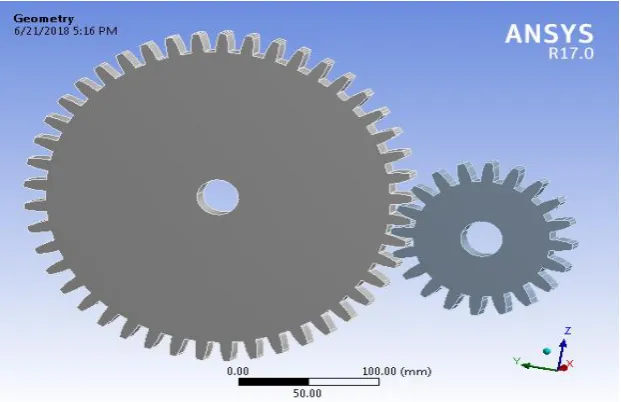
1.1 SPUR GEAR:
Fig 1.1 Spur Gear
Fig 1.1 Spur Gear
Spur gears are the most common type of gears. They are used to transmit rotary motion between parallel shafts i.e., they are usually cylindrical in shape, and the teeth are straight and parallel to the axis of rotation. Sometimes many spur gears are used at once to create very large gear reductions. Spur gears are used in many devices but not in cars as they produce large noises.
II
.
PROBLEM DEFINITIONOne of the main causes for failure of the gear tooth is bending stresses near the root of the gear and the contact stresses where the gears meet. The main objective of this paper is to analyze the bending stresses in the spur gear. When the spur gears mesh a tangential and a radial load acts upon the gear tooth and this generates stresses in the gear tooth. The radial load induces compressive stress of relatively small magnitude therefore its effect on the tooth may be neglected. The tangential load induces a bending stress which tends to break the tooth.
Failure by bending will occur when the significant tooth stress equals or exceeds either the yield strength or the bending endurance strength of the material. This paper investigates bending stress developed in gear set while transmitting power for both the steel and Aluminium as gear material. Both above said material find many applications and also each material exhibits their own characteristics during service condition, high strength, durability and load carrying capacity creates an opportunities to use Steel as gear material and in contrast aluminium as a gear material shows up unique characteristics like corrosion resistance, light weight and easy of machining.
III.
SPECIFICATION
OF
THE
GEAR
Table. 3.1: Specifications of Gear.
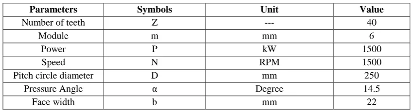
Parameters Symbols Unit Value
Number of teeth Z --- 40
Module m mm 6
Power P kW 1500
Speed N RPM 1500
Pitch circle diameter D mm 250
Pressure Angle α Degree 14.5
http: // www.ijrtsm.com© International Journal of Recent Technology Science & Management 20
ISSN : 2455-9679
[Rai et. al , 3(6), Jun 2018] Impact Factor : 2.865
IV.
PROPERTIES
OF
MATERIALS
USED
FOR
BOTH
PINION
AND
GEAR
I. Table 4.1 Structure Steel Mechanical properties
Material Field Variable Value Units
Density 7750 Kg/m3
Young’s modulus 1.93E+05 Mpa
Poisson Ratio 0.31
Shear modulus 76664 Mpa
Bulk Modulus 1.6937E+05 Mpa
Tensile Yield Strength 207 Mpa
Compressive Yield
Strength
207 Mpa
Tensile Ultimate
Strength
586 Mpa
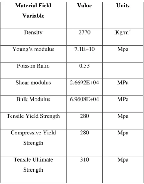
II. Table 4.2 Aluminium Alloy Mechanical properties
Material Field
Variable
Value Units
Density 2770 Kg/m3
Young’s modulus 7.1E+10 Mpa
Poisson Ratio 0.33
Shear modulus 2.6692E+04 MPa
Bulk Modulus 6.9608E+04 MPa
Tensile Yield Strength 280 Mpa
Compressive Yield
Strength
280 Mpa
Tensile Ultimate
Strength
http: // www.ijrtsm.com© International Journal of Recent Technology Science & Management 21
ISSN : 2455-9679
[Rai et. al , 3(6), Jun 2018] Impact Factor : 2.865
III. Table 4.3 Cast Iron Alloy Mechanical properties
Material Field
Variable
Value Units
Density 7200 Kg/m3
Young’s modulus 1.11E+05 Mpa
Poisson Ratio 0.28
Shear modulus 42969 Mpa
Bulk Modulus 83333 Mpa
Tensile Yield
Strength
240 Mpa
Tensile Ultimate
Strength
820 Mpa
IV. Table 4.4 Carbon Fiber Mechanical properties
Material Field
Variable
Value Units
Density 1950 Kg/m3
Young’s modulus 300000 Mpa
Poisson Ratio 0.3
Shear modulus 1.15E+05 Mpa
Bulk Modulus 2.5E+05 Mpa
Tensile Strength 5090 Mpa
http: // www.ijrtsm.com© International Journal of Recent Technology Science & Management 22
ISSN : 2455-9679
[Rai et. al , 3(6), Jun 2018] Impact Factor : 2.865
V.
THEORETICAL
STRESS
CALCULATION
Lewis Equation is used in order to calculate the theoretical bending stresses. Lewis considered the gear tooth as a cantilever beam which is loaded at its free end.
Lewis form factor is given by
Pitch line velocity
V = П DpNp/60 = П x 0.125x 1500/60 = 9.81 m/s
s s 1 .5 m YG = 0.124 – 0.684/Tp = 0.124 – 0.684/20 = 0.089
Ordinary cut gears and operating at velocity ratio is up to 12.5m/s Cv = 3/3+v
Cv = 3/3+9.81 = 0.234
Design Tooth load WT = P Cs/v
WT = 15000 x1 /9.81 = 1529.1 N
WT = ϭw.b.pc.y = ϭw.b.П m.y = (ϭo.Cv) b.Пm.y σw. = WT / b.Пm.y
σw. = 1529.1 / 22x 3.14x 6 x 0.089
σw. = 116.5 MPa
Theoretical bending stress of the designed gear = 116.5 Mpa
VI.
BENDING
STRESS
CALCULATION
USING
ANSYS
The gear is first designed in the ANSYS designer workbench. The calculated co-ordinates are plotted and an involute profile is generated. The addendum circle and dedendum circles are drawn and the profile is connected to for the individual gear tooth.
Fig. 6.1 Geometry of Spur gear for Structural Steel
http: // www.ijrtsm.com© International Journal of Recent Technology Science & Management 23
ISSN : 2455-9679
[Rai et. al , 3(6), Jun 2018] Impact Factor : 2.865
bending stress values. The bending stresses are analyzed by fixing one of the gear using fixed support and the other gear with the frictionless support. The gear with the frictionless support is then applied a moment of 96936 N-mm.
Fig.6.2 Boundary Condition applied moments on Structural Steel Gears
http: // www.ijrtsm.com© International Journal of Recent Technology Science & Management 24
ISSN : 2455-9679
[Rai et. al , 3(6), Jun 2018] Impact Factor : 2.865
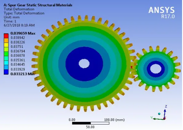
Fig. 6.4 Total Deformation on Spur gears for Structure steel
Fig. 6.5 Equivalent Von misses Stress for Cast Iron Alloy
http: // www.ijrtsm.com© International Journal of Recent Technology Science & Management 25
ISSN : 2455-9679
[Rai et. al , 3(6), Jun 2018] Impact Factor : 2.865
Fig. 6.7 Equivalent Stresses on Spur gears for Aluminium Alloy
Fig. 6.8 Total Deformations on Spur gears for Aluminium Alloy
http: // www.ijrtsm.com© International Journal of Recent Technology Science & Management 26
ISSN : 2455-9679
[Rai et. al , 3(6), Jun 2018] Impact Factor : 2.865
Fig. 6.10 Equivalent Stresses on Spur gears for Carbon Fiber
VII.
RESULT
AND
DISCUSSIONS
In this work we find value of vonmisses stresses, Aluminium Alloy, Structural Steel, Carbon Fiber and Cast Iron Alloy are respectively 59.975 MPa, 60.003MPa, 60.003MPa and 60.028 MPa And total deformation for these materials likes Carbon Fiber , Structural Steel, Aluminium Alloy and Cast Iron Alloy and, are respectively 0.018914 mm, 0.039769 mm, 0.50603 mm, and 0.09732 mm.Here we can see that we have used four different materials in all materials we will be selected composite material to other than because it is light weight and heavy duty its deformation and stresses range are considerable.
.
http: // www.ijrtsm.com© International Journal of Recent Technology Science & Management 27
ISSN : 2455-9679
[Rai et. al , 3(6), Jun 2018] Impact Factor : 2.865
Fig.7.2 Deformations comparison graph for different materials
VIII.
CONCLUSION
In this work analytical and Finite Element Analysis methods were used to predicting the Bending stresses of involute Spur gear. Bending stresses are calculated by using AGMA and ANSYS software package. Bending stresses are calculated by using ANSYS software package.
ACKNOWLEDGEMENT
We would like to offer special thanks to college departmental staff‟s especially friends, family members for giving restless effort in preparation of this paper. We also convey our sincere gratitude to many of the authors and publications who are providing material as a reference in preparing this paper.
REFERENCES
1. Prashant Kumar Singh , Siddhartha, Akant Kumar Singh An investigation on the thermal and wear behavior of polymer based spur gears, Tribology International 118 (2018) 264–272
2. Wu Jiateng, Yang Yu, Yang Xingkai, Cheng Junsheng, Fault feature analysis of cracked gear based on LOD and analytical-FE method, Mechanical Systems and Signal Processing 98 (2018) 951–967
http: // www.ijrtsm.com© International Journal of Recent Technology Science & Management 28
ISSN : 2455-9679
[Rai et. al , 3(6), Jun 2018] Impact Factor : 2.865
4. Naresh k. Raghuwanshi et al.“Effect of Back-Side contact on mess stiffness of spur gear pair by Finite Element Method.”Procedia Engineering 173 ( 2017 ) 1538 – 1543.
5. Paras Kumar, Harish Hirani, Atul Agrawal Fatigue failure prediction in spur gear pair using AGMA approach, Materials Today: Proceedings 4 (2017) 2470–2477.
6. Miryam B. Sánchez, Miguel Pleguezuelos, José I. Pedrero, Approximate equations for the meshing stiffness and the load sharing ratio of spur gears including hertzian effects, Mechanism and Machine Theory 109 (2017) 231–249.
7. Dattatray B. Vaitkar1a, Prashant N.Ulhe, Experimental Investigation and Finite Element Analysis of Contact Stresses of Spur Gear Used in Automated Lathe Machine, International Journal of Innovative and Emerging Research in Engineering Volume 4,Issue 6, 2017.
8. Xihui Liang, Hongsheng Zhang, LibinLiu , MingJ.Zuo, The influence of tooth pitting on the mesh stiffness of a pair of external spur gears, Mechanism and MachineTheory106(2016)1–15
9. Santosh S. Patil, Saravanan Karuppanan, Ivana Atanasovska ,Experimental measurement of strain and stress state at the contacting helical gear pairs, Measurement 82 (2016) 313–322.
10. Miriam B. Sánchez, Miguel Pleguezuelos, José I. Pedrero, Calculation of tooth bending strength and surface durability of internal spur gear drives,Mechanism and Machine Theory 95 (2016) 102–113.
11. Ankur Saxena, Anand Parey, Manoj Cooksey, Effect of shaft misalignment and friction force on time varying mesh stiffness of spur gear pair, Engineering Failure Analysis 49 (2015) 79–91
12. Putti Srinivasa Rao, Nadipalli Sriraj, Mohammad Farookh, Contact Stress Analysis of Spur Gear for Different Materials using ANSYS and Hertz Equation, International Journal of Modern Studies in Mechanical Engineering (IJMSME) Volume 1, Issue 1, June 2015, PP 45-52
13. Deepika Potghan, Prof. Suman Sharma Potghan, Finite element analysis of spur gear used in lathe headstock, IJESRT 4.(7): July, 2015 ISSN: 2277-9655 (I2OR), Publication Impact Factor: 3.785
14. I.S. Al-Tubi, H.Long, J.Zhang, B.Shaw, Experimental and analytical study of gear micropitting initiation and propagation under varying loading conditions, Wear328 329(2015)8–16
15. P.B.Pawar, Abhay A Utpat, Analysis of Composite Material Spur Gear under Static Loading Condition, Materials Today: Proceedings 2 ( 2015 ) 2968 – 2974
16. Sanjay K. Khavdu1, Prof. Kevin M. Vyas, comparative finite element analysis of metallic spur gear and hybrid spur gear, Volume 6, Issue 4, April (2015), pp. 117-125
17. Abhijit Mahadev Sankpal, M. M. Mirza, Contact Stress Analysis of Spur Gear by Photoelastic Technique and Finite Element Analysis, ISSN (Print): 2319-3182, Volume -3, Issue-2, 2014.
18. Seok-Chul Hwanga, Jin-Hwan Lee b, Dong-Hyung Lee c, Seung-Ho Hana, Kwon-Hee Lee,Contact stress analysis for a pair of mating gears, Mathematical and Computer Modelling 57 (2013) 40–49.
http: // www.ijrtsm.com© International Journal of Recent Technology Science & Management 29