Volume 4, Issue 11, 2017
12 Available online at www.ijiere.com
International Journal of Innovative and Emerging
Research in Engineering
e-ISSN: 2394 – 3343 p-ISSN: 2394 – 5494
Comparative Study of the Homogeneous and Janus Particles at
Fluid - fluid Interface
Prawal Prem Kishore Agarwal
Assistant Professor, Department of Chemical Engineering, Mukesh Patel School of Technology Management & Engineering, NMIMS, Mumbai, India
ABSTRACT:
This paper highlights the adsorption of spherical particles of uniform wettability and Janus particles on fluid-fluid interface. Janus particles are surface active as well as amphiphilic whereas homogeneous particles are not amphiphilic but they are surface active. Calculations and graphical analysis has been presented in this paper by doing force analysis of both types of particles to show how the amphiphilicity and ratio of polar to apolar surface areas influences the strength of particle adsorption. In a unique behavior which differs from the homogeneous particles, Janus particles always try to form preferred interfacial curvature, which best qualifies them for emulsion stabilization.
Keywords: Fluid-fluid interface, uniform wettability, Janus particles, amphiphilicity, Emulsions and foams
I. INTRODUCTION
On 9th December, 1991, P.G. de Gennes, in his noble prize address, talked about a film of Janus grains adsorbed on air-water interface and quoted an interesting difference between these grains and the surfactants[1]. Later, in 2001, Binks and Fletcher studied the difference between the adsorption of particles of uniform wettability and Janus particles at fluid-fluid interface[5]. Now a days, it has become a fascinating area of research in colloid and interfacial science. These particles have found their application in industrial processes and products such as food and crude oil emulsions and foams. They offer discrete advantages over surfactant molecules and we can also call them particulate surfactants. Their surface activity is high as compared to that of surfactant molecules and their commercial production is expected to be cost effective[4].
Particles of small size can behave as surfactants. When they are added to the system of two immiscible liquids, they can spontaneously accumulate at their interface and are capable of changing the chemical properties of that system. Particles with uniform wettability are called homogeneous particles and are found to be strongly surface active. Janus particles, on the other hand are amphiphilic as well as surface active due to which strength of Janus particle adsorption is greater than that of homogeneous particle adsorption[2]. Binks and Fletcher calculated that by increasing amphiphilicity, surface activity will be increased by a maximum of 3 times for average contact angle of 90o[5].
In this study, we are doing the graphical analysis and comparative study of the adsorption of homogeneous particles and Janus particles at oil-water interface. Homogeneous particles are characterized by the contact angle between oil-water interface and particle surface which does not depend on the positioning of three phase contact line on the surface of the particle. Janus particles have two different surface segments designated as polar and apolar, and is characterized by contact angles in accordance to the position of three phase contact line with polar or apolar segments.
We will compare the adsorption strength of homogeneous and Janus particles by graphical analysis in this paper. Janus particles are amphiphilic which means they have two surface segments having different chemical properties like wettability and they are strongly surface active. Homogeneous particles are not amphiphilic and they have uniform wettability.
In this paper, force analysis of homogeneous and Janus particles for nanosized particles has been done in which we will be able to see after what size of particle hydrostatic lift can be neglected and which type of particles form preferential curvature at interface. Janus particles show greater surface activity at fluid-fluid interfaces as compared to homogeneous particles which is proved graphically here.
II. METHODS OF ANALYSIS
Volume 4, Issue 11, 2017
13 anaylsis of homogeneous and Janus particles at interface by deriving the force equations at equilibrium conditions and plotting the graphs of force versus angular dip.
A. Force Analysis of Homogeneous Particles at Fluid-fluid Interface[9]
We want to know the conditions at which solid particles present at the Fluid-Fluid interface will stay in equilibrium. This is useful in many technological processes. Here, we are finding equilibrium position of the particle by setting the net force on the particle equal to zero. We can also do it by minimizing free energy. Vertical force balance has to be considered on the particle. The forces acting on the particle are listed below:
a. Particle weight, mg (m is the mass of the particle and g is acceleration due to gravity). b. Capillary Forces due to surface tension.
c. Contribution to buoyancy by interfacial curvature. d. Contribution to buoyancy by volume displacement.
e. Above two will add up to give vertical resultant of the hydrostatic pressure distribution around the entire particle, Fp acting upwards.
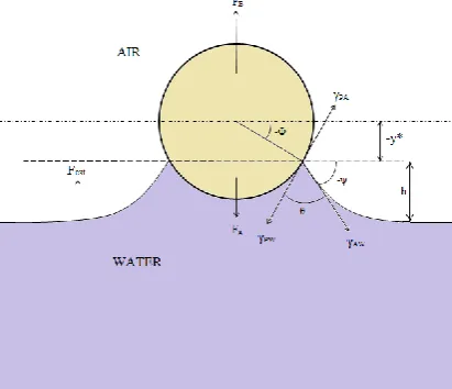
Figure 1. Positioning of the particle when interface is concave or when downward force is greater
Figure 2. Positioning of the particle when interface is convex or when upward force are greater
Symbols used signify the following definitions: R: Radius of the spherical particle
𝛾𝐴𝑊: Interfacial tension between air and water 𝛾𝑃𝑊: Interfacial tension between particle and water 𝛾𝑃𝐴: Interfacial tension between particle and air y*: height of the centre of particle from the interface 𝜃: Contact angle
Volume 4, Issue 11, 2017
14 From the figures,
𝜑 = (𝜃 + 𝜙 − 90) ……… (1) Particle weight is given by:
𝐹𝑔= 𝜌𝑝𝑔 ∗ 4𝜋𝑅3/3 …………..(2) Capillary Forces due to surface tension:
𝛾𝐴𝑊 𝑎𝑐𝑡𝑖𝑛𝑔 𝑜𝑛 𝑡ℎ𝑒 𝑐𝑜𝑛𝑡𝑎𝑐𝑡 𝑙𝑖𝑛𝑒 𝑜𝑓 𝑙𝑒𝑛𝑔𝑡ℎ 2𝜋𝑅𝐶𝑜𝑠𝜙
So,
𝐹𝛾= 2𝜋𝑅𝐶𝑜𝑠𝜙 ∗ 𝛾𝐴𝑊𝑆𝑖𝑛𝜑 ….(3)
The other two interfacial tension forces due to 𝛾𝑃𝑂 𝑎𝑛𝑑 𝛾𝑃𝑊 are not included in the force balance because they are not external forces. They are internal forces to the particle and have no significance in external force balance.
Hydrostatic Force Distribution on a Particle:
Three cases of particle at interface will be studied and governing equations will be derived for the hydrostatic force distribution on that particle.
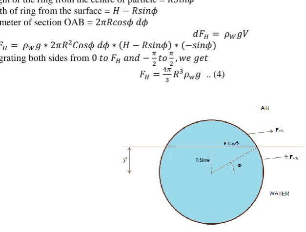
Figure 3. When the particle is fully dipped in water
From the figure 3,
Height of the ring from the centre of particle = 𝑅𝑆𝑖𝑛𝜙 Depth of ring from the surface = 𝐻 − 𝑅𝑠𝑖𝑛𝜙
Perimeter of section OAB = 2𝜋𝑅𝑐𝑜𝑠𝜙 𝑑𝜙
𝑑𝐹𝐻= 𝜌𝑊𝑔𝑉
= 𝑑𝐹𝐻= 𝜌𝑊𝑔 ∗ 2𝜋𝑅2𝐶𝑜𝑠𝜙 𝑑𝜙 ∗ (𝐻 − 𝑅𝑠𝑖𝑛𝜙) ∗ (−𝑠𝑖𝑛𝜙)
Integrating both sides from 0 𝑡𝑜 𝐹𝐻 𝑎𝑛𝑑 −𝜋
2𝑡𝑜
𝜋
2, 𝑤𝑒 𝑔𝑒𝑡 𝐹𝐻=4𝜋
3 𝑅
3𝜌𝑤𝑔 .. (4)
Figure 4. When the particle is partially submerged in water and interface is not deformed
Taking the same derivation for figure 4,
Net Force acting on a Spherical cap in air is calculated as: 𝐹𝐻𝐴= 𝜌𝐴𝑔 ∗ 𝜋𝑅3/3 *(2 − 3𝑠𝑖𝑛𝜙 + 𝑠𝑖𝑛3𝜙).. (5)
And net force action on spherical cap in water is found out to be: 𝐹𝐻𝑊= 𝜌𝑤𝑔 ∗𝜋𝑅3
3 ( 2 + 3𝑠𝑖𝑛𝜙 − 𝑠𝑖𝑛
Volume 4, Issue 11, 2017
15 So, total force acting on a particle is given by expression:
𝐹𝐻= 𝜌𝐴𝑔 ∗ 𝜋𝑅3/3 *(2 − 3𝑠𝑖𝑛𝜙 + 𝑠𝑖𝑛3𝜙) + 𝜌𝑤𝑔 ∗𝜋𝑅3
3 ( 2 + 3𝑠𝑖𝑛𝜙 − 𝑠𝑖𝑛
3𝜙).. (7)
Figure 5. When the particle is partially submerged in water and interface is deformed 𝜙 ∗ 𝑖𝑠 𝑛𝑜𝑡 𝑎 𝑣𝑎𝑟𝑖𝑎𝑏𝑙𝑒 𝑞𝑢𝑎𝑛𝑡𝑖𝑡𝑦 ℎ𝑒𝑟𝑒. It’s a constant.
From the figure,
𝑅𝑠𝑖𝑛𝜙 ∗= (𝐻 − ℎ) Or,
𝜙 ∗= arcsin
(𝐻 − ℎ) 𝑅
For spherical cap in water,
𝑑𝐹𝐻𝑊= 𝜌𝑤𝑔𝑉
= 𝑑𝐹𝐻𝑊= 𝜌𝑤𝑔(2𝜋𝑅2𝑐𝑜𝑠𝜙 ∗ 𝑑𝜙 ∗)(𝐻 − 𝑅𝑠𝑖𝑛𝜙 ∗)(−𝑠𝑖𝑛𝜙 ∗)
Integrating both sides and taking the limits at R.H.S. to be from −𝜋
2𝑡𝑜 𝜙 ∗ 𝑜𝑟 arcsin (𝐻−ℎ)
𝑅
After simplifying, we get 𝐹𝐻𝑊=𝜋𝑅2𝐻𝜌𝑤𝑔
2 (1 + 𝐶𝑜𝑠2𝜙 ∗) +
2𝜋
3 𝜌𝑤𝑔(1 + 𝑠𝑖𝑛
3𝜙 ∗).. (8)
Hydrostatic Force due to spherical cap in air will be same as Equation (5). Net Force,
𝐹𝑃= 𝜌𝐴𝑔 ∗ 𝜋𝑅3/3*(2 − 3𝑠𝑖𝑛𝜙 + 𝑠𝑖𝑛3𝜙) + 𝜌𝑤𝑔 ∗𝜋𝑅3
3 ( 2 + 3𝑠𝑖𝑛𝜙 − 𝑠𝑖𝑛
3𝜙) + 𝜌𝑤𝑔 ∗ 𝜋(𝐻 − 𝑅𝑠𝑖𝑛𝜙 ∗)(𝑅2𝑐𝑜𝑠2𝜙 ∗)] (9)
Where,
Buoyancy forces due to volume displacement:
𝐹𝐵 = 𝜌𝑤∗ 𝑔 ∗ 𝑉𝑤+ 𝜌𝐴∗ 𝑔 ∗ 𝑉𝐴 Where 𝑉𝑤 𝑖𝑠 𝑡ℎ𝑒 𝑉𝑜𝑙𝑢𝑚𝑒 𝑜𝑓 𝑡ℎ𝑒 𝑤𝑎𝑡𝑒𝑟 𝑑𝑖𝑠𝑝𝑙𝑎𝑐𝑒𝑑.
𝑉𝑤= 𝜋
6∗ 𝑅(1 + 𝑠𝑖𝑛𝜙)[3 ∗ 𝑅
2𝐶𝑜𝑠2𝜙 + 𝑅2∗ (1 + 𝑠𝑖𝑛𝜙)2]
𝑉𝑊= 𝜋 3∗ 𝑅
3∗ (2 + 3𝑠𝑖𝑛𝜙 − 𝑠𝑖𝑛3𝜙) (4)
And 𝑉𝐴 𝑖𝑠 𝑡ℎ𝑒 𝑉𝑜𝑙𝑢𝑚𝑒 𝑜𝑓 𝑡ℎ𝑒 𝑜𝑖𝑙 𝑑𝑖𝑠𝑝𝑙𝑎𝑐𝑒𝑑. 𝑉𝐴= 𝜋𝑅3/3 *(2 − 3𝑠𝑖𝑛𝜙 + 𝑠𝑖𝑛3𝜙) (5) So, Total:
𝐹𝐵= 𝜌𝑤∗ 𝑔 ∗ 𝜋 3∗ 𝑅
3∗ (2 + 3𝑠𝑖𝑛𝜙 − 𝑠𝑖𝑛3𝜙) + 𝜌
𝐴∗ 𝑔 ∗ 𝜋/3 ∗ 𝑅3 *(2 − 3𝑠𝑖𝑛𝜙 + 𝑠𝑖𝑛3𝜙)
Buoyancy Force due to Interfacial curvature:
Volume 4, Issue 11, 2017
16 Where,
(𝐻 − 𝑅𝑠𝑖𝑛𝜙) = ℎ, 𝐻𝑒𝑖𝑔ℎ𝑡 𝑜𝑓 𝑚𝑒𝑛𝑖𝑠𝑐𝑢𝑠 For equilibrium condition,
Σ𝐹 = 0 So,
𝐹𝑒𝑥𝑡= 𝐹𝛾+ 𝐹𝐵+ 𝐹𝐻+ (−𝐹𝑔).. (6)
Here we define Bond number, B as: 𝐵 = ∆𝜌𝑅2𝑔/𝛾
𝐴𝑊.. (7) Where, ∆𝜌 = (𝜌𝑤− 𝜌𝐴) By equating all the equations,
We get an expression of External force in terms of Bond number and other parameters.
𝐹𝑒𝑥𝑡 = 𝜋 ∗ 𝑅 ∗ 𝛾𝐴𝑊[𝐵 {𝜌𝑤
3∆𝜌∗ (2 + 3𝑠𝑖𝑛𝜙 − 𝑠𝑖𝑛
3𝜙 +3ℎ𝐶𝑜𝑠
2𝜙
𝑅 ) +
𝜌𝑜
3∆𝜌∗ (2 − 3𝑠𝑖𝑛𝜙 + 𝑠𝑖𝑛
3𝜙) −4𝜌𝑝
3∆𝜌} + 2𝐶𝑜𝑠ϕ
∗ Sinφ]
Values of constants and variables used: Density of oil, 𝜌𝑎= 800 𝑘𝑔/𝑚3 Density of water, 𝜌𝑤= 1000 𝑘𝑔/𝑚3 Density difference, ∆𝜌 = 200 𝑘𝑔/𝑚3 Contact Angle, θ = 90 degrees
Density of particle, 𝜌𝑝= 2630 𝑘𝑔/𝑚3; 𝛾𝐴𝑊= 50 𝑚𝑁
𝑚 = 0.05 𝑁/𝑚
Expression of External Force when gravity effects are neglected:
Gravitational effects are negligible means gravitational constant is also equal to zero. As 𝑔=0,
𝐵 = ∆𝜌𝑅2𝑔/𝛾𝐴𝑊
So, B=0 as it directly depends on ‘g’. Then,
The main expression of external force is reduced to: 𝐹𝑒𝑥𝑡 = 𝜋𝑅𝛾𝐴𝑊(2𝑐𝑜𝑠𝜙 ∗ cos 𝜑) Case: When Contact Angle is 90 degrees, θ=90 degrees, then
Above expression will be reduced to
𝐹𝑒𝑥𝑡= −𝜋𝑅𝛾𝐴𝑊𝑠𝑖𝑛2𝜙 (8)
And 𝑦
𝑅= 𝑆𝑖𝑛 𝜙
So, the graphs can also be plotted between Fext and y/R for B=0.
B. Size of the particle upto which Hydrostatic lift is significant in Force Analysis
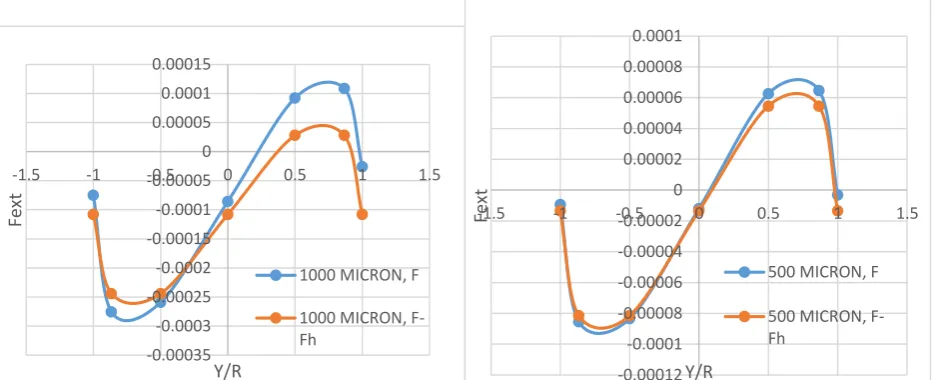
Figure 6. Comparison of the Net Force and Force without hydrostatic effects for 1000 micron& 500 micron particles -0.00035 -0.0003 -0.00025 -0.0002 -0.00015 -0.0001 -0.00005 0 0.00005 0.0001 0.00015
-1.5 -1 -0.5 0 0.5 1 1.5
Fe
xt
Y/R
1000 MICRON, F
1000 MICRON, F-Fh -0.00012 -0.0001 -0.00008 -0.00006 -0.00004 -0.00002 0 0.00002 0.00004 0.00006 0.00008 0.0001
-1.5Fext -1 -0.5 0 0.5 1 1.5
Y/R
500 MICRON, F
Volume 4, Issue 11, 2017
17
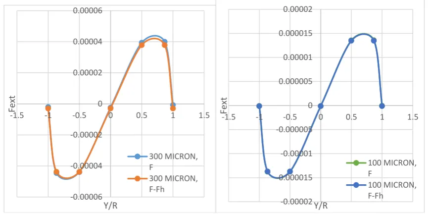
Figure 7. Comparison of the Net Force and Force without hydrostatic effects for 300 micron & 100 micron particles
Figure 8. Comparison of the Net Force and Force without hydrostatic effects for 50 micron particle
-0.00006 -0.00004 -0.00002 0 0.00002 0.00004 0.00006
-1.5Fe -1 -0.5 0 0.5 1 1.5
xt
Y/R
300 MICRON, F
300 MICRON, F-Fh
-0.00002 -0.000015 -0.00001 -0.000005 0 0.000005 0.00001 0.000015 0.00002
-1.5Fe -1 -0.5 0 0.5 1 1.5
xt
Y/R
100 MICRON, F
100 MICRON, F-Fh
-9.3998E-09
-6.81919E-06
-6.8171E-06
-1.12015E-08
6.7963E-06 6.79828E-06
-3.35139E-09 -1.3509E-08
-6.81527E-06
-6.81524E-06
-1.34513E-08
6.78828E-06 6.78819E-06
-1.36244E-08
-0.00001 -0.000008 -0.000006 -0.000004 -0.000002 0 0.000002 0.000004 0.000006 0.000008 0.00001
-1.5Fe -1 -0.5 0 0.5 1 1.5
xt
Y/R
50 MICRON, F
Volume 4, Issue 11, 2017
18
Figure 9. Comparison of the Net Force and Force without hydrostatic effects for 10 micron particle
C. Force Analysis of Janus Particles at Fluid-fluid Interface
In the previous section, equilibrium conditions for homogeneous particles at interface were determined. Here, similar analysis will be performed for nanoscale Janus particles. Their equilibrium position at fluid-fluid interface will be discussed and effect of interfacial curvature will be seen. Janus particles are non-homogeneous and that’s why they might probably behave differently at interfaces. It can be shown that Janus particles have spontaneous curvature at interfaces which plays a significant role in emulsifying 2 non-immiscible liquids. This property is different from that of homogeneous particles in which spontaneous curvature doesn’t exist.
When we consider Force balance on the Janus particles at interface, then due to their small submicron size of the order of 10 microns and nearby, body forces (Gravitation and Buoyancy can be neglected).
Capillary forces acting:
𝐹𝛾 = 2𝜋𝑅𝐶𝑜𝑠𝜙 ∗ 𝛾𝐴𝑊𝑠𝑖𝑛𝜑
Gravity forces, Contribution to Buoyancy by volume displacement and Contribution to buoyancy by interfacial curvature (Hydrostatic forces):
𝐹𝑔= 0; 𝐹𝐵= 0; 𝐹𝐻= 0 At equilibrium,
Net force on a particle= 0
Σ𝐹 = 0
𝐹𝑒𝑥𝑡 = 𝐹𝛾+ 𝐹𝑃− 𝐹𝑔= 0 𝐹𝑒𝑥𝑡 = 𝐹𝛾
We will plot curves of 𝐹𝛾 𝑣𝑠 𝑦
𝑅𝑜𝑟 𝑆𝑖𝑛𝜙.
Values of Variables and Constants: R= 10 micron
𝛾𝑂𝑊 = 0.05𝑁/𝑚.
-7.51984E-11
-1.36049E-06-1.36047E-06
-1.21526E-09
1.36031E-061.36031E-06
-4.89674E-11
-1.08072E-10
-1.36046E-06 -1.36045E-06
-9.65323E-11
1.36025E-06 1.36023E-06
-1.31151E-10
-0.000002 -1.5E-06 -0.000001 -5E-07 0 0.0000005 0.000001 0.0000015 0.000002
-1.5Fe -1 -0.5 0 0.5 1 1.5
xt
Y/R
10 MICRON, F
Volume 4, Issue 11, 2017
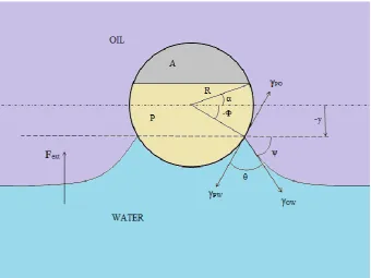
19 Figure 10. Janus particle at oil water interface when upward force is greater (‘A’ represents Apolar segment and ‘P’
represents Polar segment)
Figure 11. Janus particle at oil water interface when upward force is greater (‘A’ represents Apolar segment and ‘P’ represents Polar segment)
Parameters:
1. Θ: Contact angle measured from water.
2. Φ: It characterizes the depth of the particle at interface.
3. α: It characterizes the ratio of areas of polar and apolar part in a particle. 4. Y: Distance of contact plane from the centre of the particle.
Volume 4, Issue 11, 2017
20 1. When α=0, means apolar and polar segments are equal. Contact Angles= 0,180
Figure 12. Capillary Force versus depth of the particle when apolar contact angle is 0 and polar contact angle is 180 when polar & apolar segments are equal.
2. When α=0, means apolar and polar segments are equal. Contact Angles= 30,150
Figure 13. Capillary Force versus depth of the particle when apolar contact angle is 30 and polar contact angle is 150 when polar & apolar segments are equal.
3. When α=60, when polar segment is bigger than apolar segment. Contact Angles= 0,180
Figure 14. Capillary Force versus depth of the particle when apolar contact angle is 0 and polar contact angle is 180 when polar segment is bigger than apolar segment.
-0.000002 -1.5E-06 -0.000001 -5E-07 0 0.0000005 0.000001 0.0000015 0.000002
-1.5 -1 -0.5 0 0.5 1 1.5
Fγ
y/R
α=0, Contact Angles=0,180
alpha= 0; contact angle= 0 alpha=0; contact angle= 180
Φ=0
-0.000002 -1.5E-06 -0.000001 -5E-07 0 0.0000005 0.000001 0.0000015 0.000002
-1.5 -1 -0.5 0 0.5 1 1.5
Fγ
y/R
α=0, Contact angles=30,150
alpha=0; contact angle=30 alpha=0; contact angle=150
Φ=0
-0.000002 -1.5E-06 -0.000001 -5E-07 0 0.0000005
-1.5 -1 -0.5 0 0.5 1 1.5
Fγ
y/R
α= 60; Contact Angles= 0, 180
Volume 4, Issue 11, 2017
21 4. When α=60, when polar segment is bigger than apolar segment. Contact Angles= 30,150
Figure 15. Capillary Force versus depth of the particle when apolar contact angle is 30 and polar contact angle is 150 when polar segment is bigger than apolar segment.
5. When α=-30, when apolar segment is greater than polar segment. Contact Angles= 0,180
Figure 16. Capillary Force versus depth of the particle when apolar contact angle is 0 and polar contact angle is 180 when apolar segment is bigger than polar segment.
6. When α=-30, when apolar segment is greater than polar segment. Contact Angles= 30, 150
Figure 17. Capillary Force versus depth of the particle when apolar contact angle is 30 and polar contact angle is 150 when apolar segment is bigger than polar segment.
-0.000002 -1.5E-06 -0.000001 -5E-07 0 0.0000005 0.000001
-1.5 -1 -0.5 0 0.5 1 1.5
Fγ
y/R
α=60; Contact angles= 30,150
alpha= 60; contact angle= 30 alpha=60; contact angle= 150
Φ=60
-1.5E-06 -0.000001 -5E-07 0 0.0000005 0.000001 0.0000015 0.000002
-1.5 -1 -0.5 0 0.5 1 1.5
Fγ
y/R
α=-30; Contact angle= 0,180
alpha= -30; contact angle= 0 alpha=-30; contact angle= 180
Φ=--0.000002 -1.5E-06 -0.000001 -5E-07 0 0.0000005 0.000001 0.0000015 0.000002
-1.5 -1 -0.5 0 0.5 1 1.5
Fγ
y/R
α=-30, Contact angle= 30,150
Φ=-Volume 4, Issue 11, 2017
22 Plots when both the Contact Angles are either Concave or Convex:
Figure 18. When α=0 and Both Contact Angles are less than 90 deg, i.e. 0, 60.
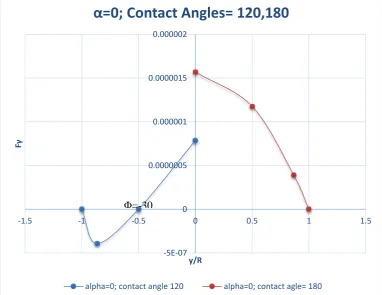
Figure 19. When α=0 and Both Contact Angles are greater than 90 deg, i.e. 120,180.
-0.000002 -1.5E-06 -0.000001 -5E-07 0 0.0000005
-1.5 -1 -0.5 0 0.5 1 1.5
Fγ
y/R
α=0; Contact Angles= 0,60
alpha=0; contact angle=0 alpha=0; contact angle= 60
Φ=3
-5E-07 0 0.0000005 0.000001 0.0000015 0.000002
-1.5 -1 -0.5 0 0.5 1 1.5
Fγ
y/R
α=0; Contact Angles= 120,180
Volume 4, Issue 11, 2017
23 III.RESULTS AND GRAPHICAL INTERPRETATIONS
A. Force Analysis of Homogeneous Particles at Fluid-fluid Interface
Graphical analysis for various sized homogeneous particles were done. Starting from 100 micron, curves started superimposing on one another and values of force expressions at different angles come closer and become almost equal at R=10 micron.
This results in a fact that we can neglect effect of Hydrostatic lift at 10 micron in our Force analysis. Undulating curves showing Forces always changing from maximum value to zero & vice versa and minimum to zero and vice versa. It is interpreted that forces are try to pin the particles at interface. When the large part of particle is submerged in oil, it tries to bring it in water and when the particle’s large part is in water, forces try to bring it in oil. When interface becomes flat with no deformation, net forces acting on particle is zero. So, homogeneous particles are not very strongly adsorbed at interface and therefore they can act as surface active agent but their strength of adsorption is not very high due to the lack of amphiphilicity in them.
B. Force Analysis of Janus Particles at Fluid-fluid Interface
Interpretation of Figure 12,13,14,15,16 &17:
Forces always try to bring the particle in a fluid in which it is preferentially wetted. When, α=ϕ, dividing plane of the particle and interfacial plane coincides. Direction of force changes. Restoration forces are occurring on the particle at this point and thus the particle undergoes small perturbations in this region trying to become stable. Hence, it can easily be interpreted that in case of Janus particles, Forces acting on them always tried to form preferred interfacial curvature and therefore it can be said that Janus particles are strongly adsorbed at interfaces and hence are highly surface active.
Interpretation of Figure 18:
At ϕ=30 deg and y/R= 0.5, capillary forces are not acting on the particle and curvature here is flat and particle is at rest. Janosity is not giving any benefits. Particle behaves like homogeneous particle and at ϕ=α, force acts in the downward direction and tries to wet it with water uptill 30 deg and then comes to rest. So, there is no preferential curvature in this case. Hence, adsorption is not strong.
Interpretation of Figure 19:
At ϕ=-30 deg and y/R= -0.5, capillary forces are not acting on the particle and curvature here is flat and particle is at rest. Janosity is not giving any benefits. Particle behaves like homogeneous particle and at ϕ=α, force acts in the upward direction and tries to wet it with oil. So, there is no preferential curvature in this case. Hence, adsorption is not strong.
IV.CONCLUSIONS
From the graphs of homogeneous particles on air-water interface, it can be concluded that Hydrostatic lift can be neglected in Force analysis of a particle for a particle with particle size around 10 micron. From the force analysis of Janus particles, it can be concluded that unlike homogeneous particles, strong adsorption of Janus particles is retained even for contact angles of 0 and 180 degrees. Also, Janosity is beneficial only when one contact angle is concave and other is convex. Particle starts behaving as homogeneous particle when both the contact angles become either concave or convex. Due to non-homogeneous behavior of Janus particles, they exhibit completely different adsorption behavior compared to homogeneous particles. In case of homogeneous particles, no preferred curvature exists whereas in case of Janus particles, preferred curvature exists under certain conditions. In the force analysis of submicron and nanosized particles, body forces have no significant effects and therefore they can be neglected in calculations. Only capillary forces are taken into account. For small sized particles, equilibrium conditions at interfaces remains unchanged due to gravity forces.
ACKNOWLEDGMENT
I would like to express my immense gratitude to Prof. V.A. Juvekar and Prof. V.M. Naik, Indian Institute of Technology Bombay, Mumbai for their patience, sustained support and encouragement throughout my studies. I am grateful to Puja Agarwala, Scientist, Aditya Birla Science and Technology Company Private Limited, to help me with my analysis methods and interfacial diagrams. I am also grateful to Chemical Engineering Department, IIT Bombay for sharing their resources that has been utilized to write this research paper.
REFERENCES
[1] P. G. de Gennes, “Soft Matter”, Rev. Mod. Phys. 1992, 64, 645.
[2] C. Casagrande, P. Fabre, E. Raphael, M. Veyssie, “Specific Properties of Amphiphilic Particles at Fluid Interfaces”, Europhys. Lett. 1989, 9,251.
[3] T. Ondarçuhu, P. Fabre, E. Raphaël and M. Veyssié, “Specific Properties of Amphiphilic Particles at Fluid Interfaces”, J. Phys. Paris, 1990, 51, 1527.
[4] Prem Kishore Agarwal, Prawal. (2017). Preparation and Characterization of Janus Particles. International Journal of Innovative and Emerging Research in Engineering. 4. . 10.26769/IJIERE.2017.4.9.191500.
Volume 4, Issue 11, 2017
24 [6] S. Jiang and S. Granick, “Controlling the geometry of amphiphilic colloidal particles”, Langmuir, 2008, 24,
2438.
[7] Clint, J.H. Curr. Opin. Colloid Interface Sci. 2001, 6, 28. [8] B. P. Binks, Curr. Opin. Colloid In., 2002, 7, 21.
[9] Scriven and Huh, Journal of Colloid and Interfacial Science, Volume 30, No. 3, July 1969.