ISSN (Print) : 2320 – 3765 ISSN (Online): 2278 – 8875
I
nternational
J
ournal of
A
dvanced
R
esearch in
E
lectrical,
E
lectronics and
I
nstrumentation
E
ngineering
(An ISO 3297: 2007 Certified Organization)
Vol. 5, Issue 9, September 2016
Simulation Study of CFSI Based Power Grid
System
Arathy S1, Shanooga Chandran2
PG Student [Power Electronics], Dept. of EEE, SJCET Palai, Kerala, India1
Assistant Professor, Dept. of EEE, SJCET Palai, Kerala, India2
ABSTRACT: This paper proposes a CFSI based power grid system. Inverters possess properties like high step-upcapabilities, high step-down capabilities andshoot-through immunity. The topologies like Z-source inverter (ZSI) andSwitched boost inverter (SBI) has low distortion ac inversion. The realization of ZSI is costlier than SBI as it requires two sets of passive filters. SBI has less component count since it has one LC pair less than ZSI but its gain is less than ZSI.This paper proposes the current-fed switched inverter (CFSI) based power grid system which combines the properties of ZSI and low passivecomponent count of SBI and the output is synchronized with the utility line. A MATLAB/Simulink model isdeveloped and is used to study the characteristics of CFSI based power grid system.
KEYWORDS:Z-source inverter (ZSI), switched boost inverter (SBI), current-fed dc/dc topology (CFT).
I.INTRODUCTION
Power inverters has various applications like electric motor speed control, induction heating, HVDC power transmission, power grid etc.The traditional VSI has limitation like its peak ac outputvoltage is slighter than the inputdc-link voltage and shoot-through in any of the inverter legs is not permitted, it will allows to flow short circuit current through the legs. Therefore,a dead-band is introduced between the switching signals ofcomplementary switches of the inverter legs, which, in turn,causes ac output distortion. Inverters with transformers are bulky andnoisy. Therefore, transformerless inverters are better choice for noise free output. Current Fed Switched Inverter (CFSI) is a topology which takes the advantage of topolgies ZSI and SBI. Z-source inverters employs a unique impedance network.ZSI couples theconverter main circuit to the power source. The Z-source concept can be applicable to ac-to-dc, ac-toac,dc-to-ac and dc-to-dc power conversion.Switched boost inverter is an another topology which have lesser passive component than ZSI. The X-shaped impedance network in ZSI is replacedby an active network in SBI. CFSI topology is made by combining the advantages of ZSI and SBI like better gain, good EMI noise immunity, less component count.
CFSI does not requires dead-band for switching signals since shoot-through state is an active state of CFSI. The output of CFSI is connected to the utility line through grid and transfer synchronously with the line. A grid based CFSI system can provide an alternate power generation like renewable sources like wind or solar power without batteries.
II.WORKING OF CFSI
Fig. 1 CFSI topology connected to grid
III.MODES OF OPERATION
Mode 1 (Shoot-through interval): In shoot-through interval (D interval) the initial voltage of the capacitor Cois equal to
Vg, and theinitial inductor current is zero before the switching signals arestarted. In the shoot-through interval (D
interval), switches Sand Si(S1-S4 or S3-S2)are turned on, and diodes Daand Dbbecome reversebiased as they are now in
parallel with Co. In this interval,source Vgand capacitor Co charge inductor L together. The voltage across inductor and
current through the capacitor during (1-D)Ts is given by,
L c
c g
I
i
V
V
v
L
Fig. 2CFSI topology in shoot-through interval
Mode 2 (Non Shoot-through interval): In nonshoot-through interval (1-D interval), switches S and Si(S1-S2 or S4
-S3)areturned off, which forces diodes Daand Dbto turn on, andthe inductor charges Coand power are delivered to the ac
loadthrough the inverter. Here, turning off switch Sidenotes thepower interval or zero interval of the inverter. The
voltage across inductor and current through the capacitor during (1-D)Ts is given by,
Fig. 3CFSI topology in non shoot-through interval
Turning on of both switches of an inverter leg is a valid state of CFSI, it has better EMI and noise immunity. The
i L c
c g
I I i
V V vL
ISSN (Print) : 2320 – 3765 ISSN (Online): 2278 – 8875
I
nternational
J
ournal of
A
dvanced
R
esearch in
E
lectrical,
E
lectronics and
I
nstrumentation
E
ngineering
(An ISO 3297: 2007 Certified Organization)
Vol. 5, Issue 9, September 2016
line. High-quality modern grid connected inverter system has a fixed unity power factor. Reactive power supply to the grid is essential for keeping the voltage in limits during high production.
IV.SIMULATION AND RESULTS
The simulation result was done in MATLAB/Simulink.The simulink model of the current fed switched inverter (CFSI) is shown in figure 4. CFSI synchronize its frequency with that of the grid at 50Hz. Closed loop control is adopted for the CFSI based grid system. Modified PWM scheme is developed for the gating of switches in CFSI.
Fig. 4 Simulink model of CFSI based power grid system
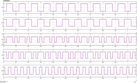
The gate pulses are generated for switches S1,S2,S3,S4,andS are plotted in figure 5. Modified PWM control strategy is
Fig. 5Gating pulses for switches S1, S2, S3, S4 and S respectively
Figure 6. shows the input dc voltage and dc link voltage of CFSI based grid system.
ISSN (Print) : 2320 – 3765 ISSN (Online): 2278 – 8875
I
nternational
J
ournal of
A
dvanced
R
esearch in
E
lectrical,
E
lectronics and
I
nstrumentation
E
ngineering
(An ISO 3297: 2007 Certified Organization)
Vol. 5, Issue 9, September 2016
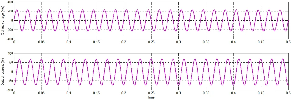
The output voltage and current waveforms through the grid is shown in figure 7.
Fig. 7Output voltage and output current through the grid
VI. RESULTS AND DISCUSSION
In figure1, CFSI topology based grid connected system is shown. It comprises of 5 switches and gate pulses are given to the switches through pwm gate signal generation. In figure 4, represents the simulink model of CFSI based power grid system. In figure 7, the output voltage and output current through the grid is shown. CFSI model and grid is connected and synchronized. Iin figure 5, the gating pulses for switches S1, S2, S3, S4 and S respectively are plotted. They are generated through modified PWM technique and shoot through signals are generated through ORed of other gating signals.
V. DESIGN
The inductor current ripple is given by,
s c g
L
DT
L
V
V
i
The capacitor voltage ripple is given by,
s L
c
DT
C
i
V
The input voltage, Vg = 30V
DC link voltage, Vc = 350V
Maximum duty ratio, Dmax = 0.46
Switching time, Ts=52μs
The output ac filter can be designed by keeping unity gain at 50Hz. The output inductor and capacitor value can be derived from the equation,
)
(
1
o AB f f f f fv
v
L
iL
L
R
dt
diL
f AC o f f oC
R
v
C
iL
dt
dv
Capacitor is designed for 0.15% ripple for 350V dc link voltage and inductor is designed for 50% peak to peak ripple rating.
VII.CONCLUSION
The simulation study of current fed-switched inverter based grid connected system is done. The output of CFSI is connected to the grid to interface with the utility line. The proposed inverter based grid system hasboth buck and boost capabilities. The CFSI topology has additional benefits such as reduced noise,and better EMI immunity.
REFERENCES
[1] M. C. Chandorkar, D. M. Divan, and R. Adapa, “Control of parallel connected inverters in standalone ac supply systems,” IEEE Trans. Ind. Appl., vol. 29, pt. 1, no. 1, pp. 136-143, Jan./Feb. 1993.
[2] D. Maksimovic and S. Cuk, “Switching converters with wide dc conversion range,” IEEE Trans. Power Electron., vol. 6, no. 1, pp. 151-157, Jan. 1991
[3] F. Z. Peng, “Z-source inverter,” IEEE Trans. Ind. Appl., vol. 39, no. 2, pp. 504 -510, Mar./Apr. 2003.
[4] F. Blaabjerg, Z. Chen, and S. B. Kjaer, “Power electronics as efficientinterface in dispersed power generation systems,” IEEE Trans.PowerElectron., vol. 19, no. 5, pp. 1184-1194, Sep. 2004.
[5] M. E. Ropp and S. Gonzalez, “Development of a MATLAB/Simulinkmodel of a single-phase Grid-connected photovoltaic system,” IEEETrans. Energy Convers., vol. 24, no. 1, pp. 195-202, Mar. 2009.
[6] L. Chen and F. Z. Peng, “Dead-time elimination for voltage source inverters,” IEEE Trans. Power Electron., vol. 23, no. 2, pp. 574-580, Mar. 2008.
[7] J. M. Carrasco, L. G. Franquelo, J. T. Bialasiewicz, E. Galvan, R. C. P.Guisado, M. A. M. Prats, J. I. Leon, and N. Moreno-Alfonso, “Powerelectronicsystems for the grid integration of renewable energy sources:A survey,” IEEE Trans. Ind. Electron., vol. 53, no. 4, pp. 1002-1016,Jun. 2006.
[8] R. W. Erickson and D. Maksimovic, Fundamentals of Power Electronics,2nd ed. New York, NY, USA: Springer, 2001.S. Mishra, R. Adda, and A. Joshi, “Inverse Watkins-Johnson topologybasedinverter,” IEEE Trans. Power Electron., vol. 27, no. 3, pp. 1066-1070, Mar. 2012. [9] T. K. K wang, S. Masri, " Single phase grid tie inverter for photovoltaic application," in Proc. IEEE Sustainable Utilization and Development
in Engineering and Technology Conj, pp. 23-28. Nov 2010. B. K. Bose, “Energy, environment, and advances in power electronics,”IEEE Trans. Power Electron., vol. 15, no. 4, pp. 688-701, Jul. 2000.
[10] Bo Yang; Wuhua Li; Yi Zhao; Xiangning He; , "Design and Analysis of a Grid-Connected Photovoltaic Power System,"Power Electronics, IEEE Transactionson , vol.25, no.4, pp.992-1000, April 2010
[11] Yi Huang; Miaosen Shen; Peng, F.Z.; Jin Wang; “Z-Source Inverter forResidential Photovoltaic Systems”, IEEE Transactions on Power Electronics,Volume 21, Issue 6, pp. 1776-1782, Nov. 2006.