Papers & Publications: Interdisciplinary Journal of
Undergraduate Research
Volume 5
Article 7
2016
Computer Vision Based Object Detection and
Tracking in Micro Aerial Vehicles
Richard F. Chapman
Florida Southern College
H. David Mathias
Florida Southern College
Follow this and additional works at:
http://digitalcommons.northgeorgia.edu/papersandpubs
Part of the
Artificial Intelligence and Robotics Commons
This Article is brought to you for free and open access by the Center for Undergraduate Research and Creative Activities (CURCA) at Nighthawks Open Institutional Repository. It has been accepted for inclusion in Papers & Publications: Interdisciplinary Journal of Undergraduate Research by an authorized editor of Nighthawks Open Institutional Repository.
Recommended Citation
Chapman, Richard F. and Mathias, H. David (2016) "Computer Vision Based Object Detection and Tracking in Micro Aerial Vehicles,"Papers & Publications: Interdisciplinary Journal of Undergraduate Research: Vol. 5 , Article 7.
Acknowledgments
40 | Chapman and Mathias
Object Detection and Tracking in Micro Aerial Vehicles
U
nmanned and/or autonomous flight has applications in many forms of aviation, from remotely controlled predator drones to Amazon’s much-discussed drone delivery program. One form of autonomous flight involves instructing an aerial vehicle to visually track or follow another object. Systems that successfully implement this can be used in tasks ranging from serious, such as surveillance for national security and search and rescue operations, to frivolous, such as capturing the ultimate moving selfie. In this paper, we present a system comprised of a small, camera-equipped drone and a ground-based laptop computer with software to facilitate control. In two separate though related imple-mentations, the drone either follows a target object or finds and flies to it.Micro Aerial Vehicles (MAVs), popularly known as drones, make unmanned flight research safe and inexpensive. While such vehicles are typically quite small, often weighing only a few pounds or less, they can be very capable. Thanks to high-bandwidth communication, even very lightweight drones with little onboard processing capability can undertake tasks that require significant computation. For example, in this work, we capture a video stream using an onboard camera but send the images over Wi-Fi to a laptop for processing. The computer uses the image data to determine flight adjustments and communicates them to the drone over the same Wi-Fi connection. This allows vehicles lacking sufficient thrust, or without connectivity options, to incorporate an onboard computer to be used for research projects such as this.
The ability to detect and track objects is an essential step in the solutions to many problems. We experience this frequently, perhaps daily, without realizing it. Object tracking is incorporated into systems designed for tasks such as surveillance, navigation, and search and rescue operations. Most of these solutions are completely reliant on the capabil-ities of a computer system to acquire and track objects, including people, in an environment.
Though there are multiple methods for tracking an object, visual tracking is frequently used. One reason for this is likely the affordability of cameras capable of capturing the required images and the broad array of software available of processing them. Thus, there are many instances of tracking systems based on visual data. For example, military and police operations may utilize visual tracking systems for surveillance. One such system along national borders allows for the detection and tracking of people suspected of attempting to enter a country illegally [1].
Tracking systems have also recently become prevalent in search and
Computer Vision Based Object Detection
and Tracking in Micro Aerial Vehicles
Richard Chapman is an undergraduate Computer Science major at Florida Southern College. In addition to CS, he is interested in Math, Physics, and Astronomy. He is an exec-utive in the campus Astronomy Club as well as the Computer Science Club, and is involved with many events in the department. Some of his non-academic interests include graphic design, films, and reading. Richard is entering his senior year at Florida Southern. After grad-uation, he plans to attend graduate school to obtain a Master’s of Science degree, perhaps continuing his research in computer vision. Dr. David Mathias is chair of Computer Science and the Charles and Mildred Jenkins Chair in Mathematics and Computer Science at Florida Southern College. He received a B.S. in Computer Science from the University of Delaware and M.S. and D.Sc. degrees in Computer Science from Washington University in St. Louis. His primary research area is genetic algorithms. He teaches a wide array of courses but has a particular fondness for teaching Analysis of Algorithms.
Richard F. Chapman and
H. David Mathias, DSc
rescue efforts, allowing ground crews and emergency personnel to locate individuals who may be in danger. Some applications in this domain include the ability for lifeguards to detect people who might be drowning [2], and for firefighters, using infrared and sonar, to locate people trapped in a fire [3].
Visual object detection and tracking is one part of a larger area of research known as computer vision. Computer vision is the study of analyzing, processing, and under-standing images from the real world in a quantifiable manner in order to produce numerical or symbolic information [4]. Only recently has the technology reached a level of accuracy that allows integration into systems capable of navigation and control of a vehicle. New advancements will, for example, make self-driving cars possible by allowing computers to map other vehicles on the road and monitor their motions relative to the au-tonomous system.
In this work, we demonstrate a system that finds an object in its environment (based on color) and either flies to it or follows it. In sub-sequent sections of this paper, we describe the research that was our inspiration and starting point, describe our drone and other tools, outline our solution to the problem, and discuss the results and future directions.
Previous Work
MAVs have been the subject of a large body of research in several areas of computer science. Given the ease with which cameras can be incorporated into small, flying vehicles, it is not surprising that many results are related to computer vision. Many of these focus on vi-sion-based autonomous navigation, typically in GPS-denied environments such as inside buildings [5][6][7][8][9].
Another type of problem involves visually tracking an object. This can include tracking another drone, a ground-based vehicle, a person, or an object [10][11][12][13]. Of particular interest to us is the work of Levy [14], in which a MAV visually tracks and follows a ball held and moved by a person.
Levy’s system allows a drone to track a solid
Figure 1: Orientation of the X, Y, and Z axes. This orienta-tion is standard in aviaorienta-tion at all levels. The arrow indicates the front of the vehicle and the orientation of the front-facing camera.
green ball through the environment along two axes of motion, X and Z but not Y (see Figure 1). His system does not seek the target; it must be placed in view of the vehicle’s camera. He has made his software, which includes a computer vision component and a vehicle control component, available to the community. The vision component is implemented in Python; the vehicle control component in C++. We use this system as the starting point for our research.
Flight Platform and Tools
Choosing the correct MAV for a project such as this is critical. We had a number of require-ments: suitable for indoor flight, able to hover reliably, onboard camera, communication channel capable of streaming video, and an API that allows complete control via a high-level pro-gramming language. Total cost of the package was an additional constraint.
42 | Chapman and Mathias
Object Detection and Tracking in Micro Aerial Vehicles
the front camera captures images at 720p, the streamed framerate is approximately 30 frames per second. Communication is via a Wi-Fi access point created by the vehicle. The API provided by Parrot supports a C++ interface allowing direct control of roll, pitch, yaw and thrust, making possible complete control of the vehicle via software.
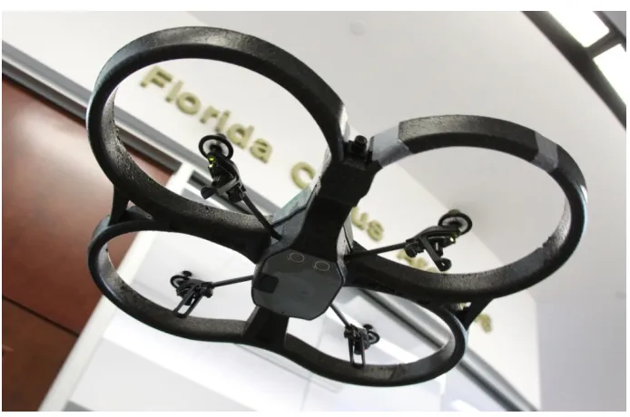
While relatively small, the A.R. Drone 2.0 is equipped with a full array of flight sensors. These include a 3 axis accelerometer for detecting motion; a 3 axis gyroscope for determining attitude; and a 3 axis magnetometer for deter-mining heading. In addition, a downward facing ultrasound unit supplies altitude information when the drone is within 5m of the ground while a barometer is used for higher flight. Onboard processing, for functions such as stabilization, is provided by a 32 bit ARM Cortex A8 processor running at 1 GHz.
While the MAV is an important component of our overall system, other hardware com-ponents are necessary. First among these is a computer capable of processing the video stream, determining required navigational adjustments, and sending the corresponding commands to the vehicle. For this purpose, we used a Dell Latitude laptop with Intel Core i7 processor running at 3 GHz. On the computer,
Figure 2: The A.R.Drone 2.0 in flight. The front-facing camera, bottom-facing camera and
ultra-sound sensors.
we installed Ubuntu Linux 14.04. The broad array of open source software available makes Linux a good choice for scientific research.
One important safety procedure when flying a MAV under computer control is to have backup control capability. This allows one to take control of the vehicle if the software fails to function as intended. In our case, because our missions are indoors and there is no need to return to a takeoff location, this involves only instructing the drone to land. For this purpose, we use a Microsoft Xbox controller connected to the ground-based computer via USB. This controller is also used for takeoff and to initiate computer control of the MAV.
Computer Vision and Object Detection
this limitation is not problematic.
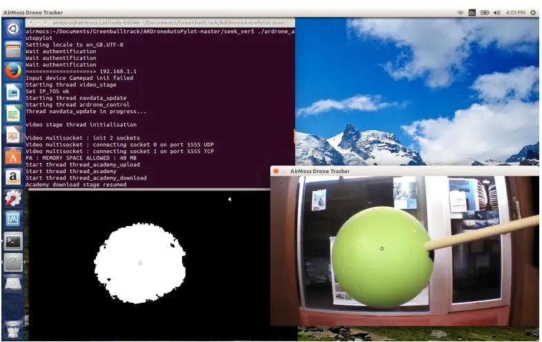
In this work, computer vision makes possible the detection and identification of the object that we want the MAV to track. Several methods could be used to achieve this; our system uses a form of blob detection that dis-tinguishes objects by color. For each frame of the video stream transmitted by the MAV, the computer examines the full color image. The image is converted to monochrome by stripping away pixels that are not comprised of the pre-determined color we wish to track, or are not within a certain threshold of that color. This leaves us with a binary image representing only the pixels we do want to track in white and the pixels we do not want to track in black. An example of the result is seen in the monochrome image in Figure 3 below.
The window on the right shows the video feed from the camera on the A.R. Drone 2.0. The window on the lower left shows what the software sees as green. Shadows and highlights prevent the detected object from appearing as a complete circle. Note the small patch of green detected above and to the right. This is a green element on a poster across the hall. Detection of such small elements presents problems in some cases.
Figure 3: Screen capture of our system in use.
Tracking the object depends, in part, on how big it appears to be in the frame. This can be used to determine relative distance to the object. If the object appears smaller, the MAV is farther away; larger indicates that the MAV is closer. For this reason, we need an object for which the apparent size is constant, independent of viewing angle. The apparent surface area of a cube, for example, changes with one’s position relative to it. A sphere, on the other hand, is not subject to this. Regardless of the angle from which a sphere is viewed, it appears as a circle with the same radius as the sphere, fulfilling our requirement. We use a 6” Styrofoam ball painted light green and mounted on a wooden rod. This provides a very inexpensive and effective target.
44 | Chapman and Mathias
Object Detection and Tracking in Micro Aerial Vehicles
in the object.
In aviation, the axes of 3-dimensional space are denoted X, Y, Z. The X and Y axes are orthog-onal to the Earth’s radius and run East/West and North/South respectively. The Z axis is radial. Figure 1 provides an illustration of this frame of reference. As noted in the Previous Work section, Levy [14] provides 2-dimensional control in the vertical plane defined by axes X and Z. One goal of this work is to introduce control in the Y axis.
Depth Perception
Control in the vertical plane [14] is achieved by calculating the centroid of the target sphere and attempting to keep it centered in the camera frame. This is facilitated by sending roll (left/ right) and thrust (up/down) adjustments to the vehicle. Our first result provides tracking in the
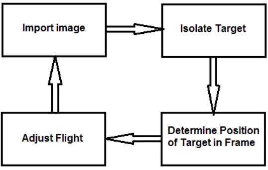
Y axis as well. The goal for the third dimension, as with the first two, is to maintain, as closely as possible, a position relative to the target object. Unfortunately, position of the centroid within the video frame does not aid in this determina-tion in the Y dimension because motion along that axis does not affect the position of the target within the video frame. We must instead attempt to determine distance to the target. We implement two solutions to this problem. Figure 4 provides an abstract outline of the software.
Determining distance to an object, a form of depth perception, is easily achieved with binocular vision. Our brains perform this task
Figure 4: High-level schematic of the software. This cycle is repeated many
times per second, allowing fine control of the vehicle’s flight. continually. In computer vision, use of two cameras allows algorithms to leverage
binocular disparity – the offset of features in images from cameras that are a small distance apart – to calculate the distance to target. Monocular vision makes this calculation impossible as there is only a single image and, therefore, no disparity. Because the A.R. Drone 2.0 has only a single front-facing camera, our algorithm must approximate distance using monocular vision. To achieve this, we do not attempt to calculate distance to the object but instead track relative distance, determining only if the vehicle is moving toward or away from the target.
As soon as the target sphere is in the camera frame, OpenCV detects it. Once detected, we are able to request its apparent area in pixels. This area is stored and serves as a baseline for later comparison. In subsequent images, the current apparent area of the target is determined. If this area is greater than the baseline, the vehicle is closer to the target than it was initially. If smaller, the vehicle is farther from the target. Correcting for this difference is a simple matter of sending a command temporarily adjusting the pitch of the MAV, moving it slowly forward or backward. Calculations, and the resulting adjustments, are performed for every video frame. We refer to this as the First Area Version.
Though effective, this solution is not perfect. While calculating changes in the area of the target object will tell us if the MAV is moving closer or further away, it will not allow us to determine the actual distance to the object, nor more importantly, the rate of change of the distance. The latter point is not obvious, but the change in apparent area is not linear with change in distance. Knowing the rate of change would allow for more accurate, variable pitch adjust-ments which would result in more accurate tracking of the target in the Y dimension.
control [16], addresses, to a degree, the diffi-culty with determining rate of change. PID, an acronym for Proportional-Integral-Derivative, is a form of feedback control. PID controllers are used in many industrial applications and are effective at generating a response to a cal-culated error in the system. The error, however, is not a single value. While the current error is addressed via the proportional term, past errors are addressed via the integral term and the deriv-ative term attempts to predict future error based on the rate of change of the error value. The purpose of the integral term is to allow increased adjustment if the rate of change in the error is insufficient.
The key to achieving good PID control is determining effective coefficients for the P, I and D terms. This process, known as tuning, can be quite challenging and something of an art. A system that is not adequately tuned may exhibit symptoms such as oscillations, a common issue with PID control. Oscillation is caused by repeated error corrections that are too large, causing the system to overshoot the goal.
Levy integrated a simple PID control-ler, written in Python, in his system [14]. We have adapted it for the Y dimension and have attempted to tune it. However, oscillations are sometimes observed as the vehicle approaches the target. The effect is most pronounced in the
X axis. Because the magnitude of the oscillations diminishes with time, the system is reasonably stable.
Thus far, the First Area implementation performs better than the PID implementation, providing a more stable result subject to less error along the Y axis. With further tuning of the PID coefficients, we expect to improve flight characteristics of that version which may allow it to outperform the simpler First Area version.
Searching for the Target
In the versions described in the previous section, the target object is intentionally placed in the camera’s field of view to begin the tracking task. While the computer vision algorithms must detect the target, there is no need for target ac-quisition. Here we describe a version that first searches for the target and then flies to it. When
this version is run, after instructing the MAV to takeoff, the software sends yaw commands so that the vehicle will slowly rotate in the horizon-tal plane. During this phase, the vision system attempts to detect the target object. When the target is located, the drone is maneuvered so that the object is centered in the camera frame. Once this is accomplished, it flies forward toward the object. When the target fills a predetermined percentage of the video frame, the drone is suf-ficiently close to the target and stops. At this point, it can enter hover mode and await further instructions or remain in autopilot mode to continue tracking the object if it should move.
One problem encountered with early versions of this implementation involved false positive identification of the target. In these cases, the vision system would sometimes detect an extremely small object of similar color, such as a detail on a poster on the wall. This did not occur in solutions to the first problem we consid-ered because when running those versions, the much larger, intended target was always visible to the camera. To address this, we added a check to ensure that to be detected as the target, an object must exceed a size threshold. Thus we can control the environment to ensure the absence of sufficiently large objects that might result in a false positive while the system ignores small objects. With this modification, the system performs quite well.
Future Work
46 | Chapman and Mathias
Object Detection and Tracking in Micro Aerial Vehicles
to a different flight platform on which we can mount a higher quality camera will address this.
Apart from shortcomings in the project so far, there are a number of areas for future study. In the future we hope to continue to implement a system that can follow more complex targets such as people or, perhaps, other MAVs. Additionally, we would like to achieve autonomous visual navigation of more complex environments, such as obstacle courses, without following a target object.
In recent work, we have begun the process of porting our system to a different micro aerial vehicle: the 3DR Iris+. The Iris+ is a more capable vehicle better suited to outdoor flight. It does not include a camera; therefore, we have mounted a Logitech C920 webcam. This camera is of higher quality than that integrated into the A.R. Drone 2.0 and in preliminary testing appears to have solved the problem of sensitivity to light level. We have only recently begun im-plementing the flight control code for the Iris+ and have performed very limited flight testing at this time.
References
[1] E. Felemban, Advanced Border Intrusion De-tection and Surveillance Using Wireless Sensor
Network Technology. International Journal
Communications, Network and System Sciences, 6, May 2013.
[2] H. Eng, K. Toh, A. Kam, J. Wang, W. Yau, An Automatic Drowning Detection Surveillance System for Challenging Outdoor Pool Environ-ments. In proceedings of Ninth IEEE Interna-tional Conference on Computer Vision, 2003. [3] Y. Aoki, Human and Object Detection in
Smoke-filled Space Using Millimeter-wave Radar Based Measurement System. Research-gate, 2006.
[4] E. Learned-Miller, Introduction to Computer Vision, 2011, people.cs.umass.edu/~elm/Teach-ing/Docs/IntroCV_1_19_11.pdf, retrieved January 26, 2016.
[5] F. Andert, F. Adolf, L. Goormann, J. Dittrich, Autonomous Vision-Based Helicopter Flights
Through Obstacle Gates. J. Intelligent Robot
Systems, 57, 2010.
[6] C. Bills, Joyce Chen, A. Saxena, Autonomous MAV Flight in Indoor Environments using
Single Image Perspective Cues. In proceedings of IEEE International Conference on Robotics & Automation, 2011.
[7] J. Engel, J. Sturm, D. Cremers, Camera-Based Navigation of a Low-Cost Quadrocopter. In proceedings of International Conference on Intelligent Robot Systems, 2012.
[8] J. Lugo, A. Zell, Framework for Autonomous
On-board Navigation with the A.R. Drone. J.
Intelligent Robot Systems, 73, 2014.
[9] M. Saska, T. Krajnik, J. Faigl, V. Vonasek, L. Preucil, Low Cost MAV Platform A.R. Drone in Experimental Verification of Methods for Vision Based Autonomous Navigation. In proceedings of IEEE Conference on Intelligent Robots & Systems, 2012.
[10] A. Masselli, A. Zell, A Novel Marker Based Tracking Method for Position and Attitude Control of MAVs. In proceedings of Interna-tional Micro Air Vehicle Conference and Flight Competition, 2012.
[11] K. Wenzel, A. Masselli, A. Zell, Automatic Takeoff, Tracking and Landing of a Miniature
UAV on a Moving Carrier Vehicle. Journal of
Intelligent Robotic Systems, 61, 2010.
[12] K. Wenzel, A. Masselli, A. Zell, Visual Tracking and Following of a Quadrocopter by Another Quadrocopter. In proceedings of IEEE Inter-national Conference on Intelligent Robots & Systems, 2012.
[13] B. Yun, B. Chen, K. Lum, T. Lee, Design and implementation of a leader-follower cooperative
control system for unmanned helicopters.
Jour-nal of Control Theory and Applications, 8, 2010. [14] S. Levy, A.R. Drone AutoPylot – Auto-Pilot the
Parrot A.R. Drone from Python, 2013, home. wlu.edu/~slevy/software/ardrone_autopylot, retrieved January 2015.
[15] P-J. Bristeau, F. Callou, D. Vissiere, N. Petit, The Navigation and Control Technology Inside the A.R. Drone Micro UAV. In proceedings of
18th IFAC World Congress, 2011.
[16] K. Åström and T. Hägglund, PID Controllers:
Theory, Design and Tuning. ISA: The
Instru-mentation, Systems and Automation Society, Research Triangle Park, NC. 343pp, 1995.
Acknowledgements