Tribology in Industry
www.tribology.rsInvestigation of Wear Pattern in Piston Ring of an
IC Engine
K.H. Niralgikar
a, M.A. Bulsara
baMechanical EngineeringDepartment, SVIT, Vasad, Anand, Gujarat,India
bMechanicalEngineering Department, GCET, Vallabh Vidyanagar, Anand, Gujarat,India.
Keywords:
Piston ring Wear
Piston ring profile Wear volume
A B S T R A C T
Piston Ring, as small as it appears, plays quite an important role in contribution to friction and wear in an IC engine. As a first approximation most wear models, have quantified wear of a piston ring in terms of total wear volume, total weight loss or depth of the wear scar with an underlined assumption that wear is uniform along the circumference. This research work presents the results of wear calculation of the top piston ring of an IC Engine by measuring piston ring profile at 9 different angular sections, constituting 8 sectors of piston ring. Piston ring profile was measured over axial width of the worn-out piston ring at 13 different locations along the axial direction for each of the 9 sections. Volume loss for each of the 8 sectors is calculated by comparing piston ring profile of worn-out piston ring with profile of new piston ring of same type. It is observed that the wear volume loss is different for different sectors. It can be inferred from wear pattern (volume loss) that different areas of piston rings undergo different regimes of lubrication. It is likely that different sectors of piston ring undergo boundary, mixed and hydrodynamic lubrication regimes to different extents along the circumference of the top piston ring.
© 2019 Published by Faculty of Engineering
Corresponding author:
Kirti H. Niralgikar Mechanical Engineering
Department, SVIT, Vasad, Anand, Gujarat, India.
E-mail:
1. INTRODUCTION
A piston ring experiences wear due to the asperities contact between piston ring and the cylinder liner. Oil film thickness between two mating surfaces determines the three regimes of lubrication which are boundary lubrication, mixed lubrication and hydrodynamic lubrication. Wear of piston ring has been considered as uniform along the circumference by many researchers in past. Pike W.C. and D.T. Spillman [1] have measured total wear rate of the top piston ring by radioactive
tracer technique at different torques of motored engines. T.H.C. Childs and F. Sabbagh [2] have simulated the real engine conditions by pin-on-disk tests and have calculated that total wear volume loss in a top piston ring due to boundary lubrication conditions. P.C. Nautiyal et al. [3] have given a theoretical model for piston ring wear rate in terms of energy of absorption, the material properties, and the operating conditions. Experimentally wear was measured by the radiotracer technique and the total wear rate was calculated by the authors. Priest et al. [4] have
R
ES
EA
R
developed a numerical model that predicts wear of piston ring at one particular point on the circumference of the piston ring and these results has been compared with the experimental results. S. Tung and Y. Huang [5] have developed a three body wear abrasion model for the piston ring. Combining the effects of surface roughness and oil degradation, the total wear volume loss due to the abrasive wear has been investigated. There has been no mention of variation in wear of the piston ring in the research. J.J. Truhan and P.J. Blau [6] have developed a test method to evaluate wear behavior of candidate piston ring and cylinder liner materials for heavy duty diesel engine applications with realistic lubricants. The authors have measured the wear scar geometry at a particular crank angle and calculated the total wear volume loss rather than the variation. M.A. Bulsara et al. [7] have measured wear profile along a circumference of the piston ring of different makes and have compared it with a new piston ring. The authors have mentioned about the variation of wear volume along the circumference of the top piston ring. E. Smith [9] showed through design of experiments (DOE) that the oil film thickness gives an inference of total wear of the piston ring. M. Zheng et al. [10] have quantified total wear using Archard’s wear equation. P.C. Mishra [11] has given a contact conjunction of a piston ring-pack and rough out-of-round cylinder profile is modeled to analyze the sources of the total wear rate. Research carried out till now has emphasized on total wear volume or wear depth at a particular region of the piston ring. This research focuses on the variation of the wear volume along the circumference of the top piston ring.
2. EXPERIMENTAL SETUP
Volumetric wear of piston ring was calculated by comparing volume of worn piston ring with volume of new (unworn). Volume of worn piston ring was calculated by measuring piston ring axial profile at 9 different sections along the circumference and calculating the volume by interpolation between two successive sections. Volume of new (unworn) piston ring was calculated based on the ring face profile of new piston ring of same make.
A worn-out piston ring from Hero Honda Splendor has been selected for the study as the motorbike is
the bestselling motorbikes with consistent sales of 2 lakh units in India every year. The specification of the engine has been given in Table 1.
Table 1. The specification of the engine.
Engine capacity: 97.2 cc, 4 stroke, single cylinder, OHC
The mileage of the bike 60 km/ liter
Bore Diameter 50 mm
Stroke Length 49.5 mm
Piston Ring outer diameter 50 mm Piston ring inner diameter 47 mm
Piston Ring Number 100, Usha Make
Piston Ring axial thickness 1 mm The total travel of the piston 241700 km.
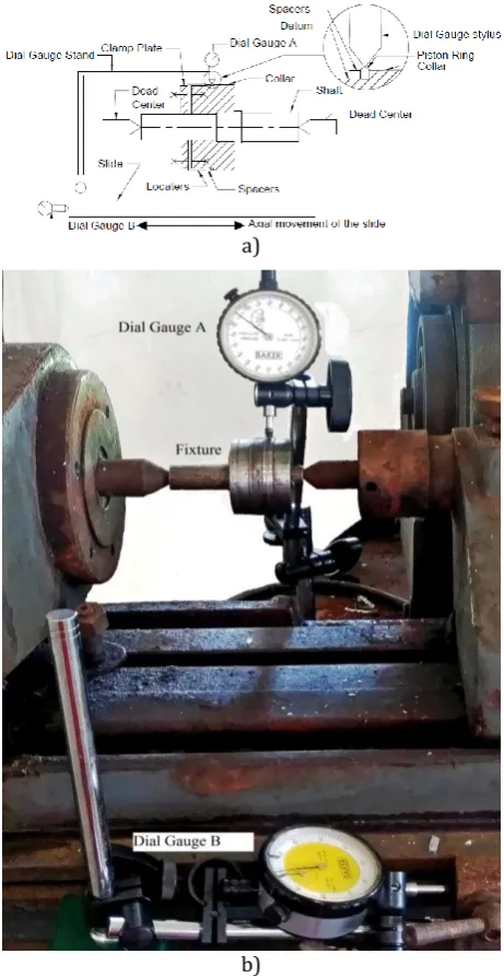
The schematic diagram of the measurement setup is as shown in Fig. 1.
a)
c)
Fig. 1. a) Schematic diagram for measuring profile of piston ring, b) Photograph of the measurement setup, c) The schematic diagram of the fixture for measuring the profile of the piston ring.
A fixture was designed and manufactured for the purpose of measurement of the piston ring profile as in Fig. 1a. The fixture consists of shaft, collar, clamp-plate and spacer rings. The shaft was machined and ground between centers on cylindrical grinding machine. Outer diameter and inner diameter of the collar was also machined and ground between centers on cylindrical grinding machine to have tight fit between shaft and collar. A shoulder is provided on the collar so that the piston ring can rest against the shoulder when clamped with clamp-plate with required number of spacer rings.
The collar is assembled with shaft with tight fit assembly. Piston ring under test is mounted on the collar such that it rests on the shoulder, along with spacer rings. Both are fastened as one unit, together with clamp-plate screwed to the collar as shown in Fig. 1c .The fixtures along with piston ring is mounted between centers on centre lathe. Two dial gauges are used ‘Dial Gauge A’ and ‘Dial Gauge B’ for the measurement of piston ring axial profile. ‘Dial Gauge A’ has least count of 0.001 mm and that of ‘Dial Gauge B’ is 0.01 mm. Piston ring is mounted on the collar such that the inner diameter of piston ring rests on the collar to ensure same datum for every measurement. Stylus of ‘Dial Gauge A’ is mounted on specimen piston ring as shown in Fig. 1a such that it can measure the variation in piston ring profile in axial direction.
2.1 Measuring the ring profile along the axial direction of the piston ring
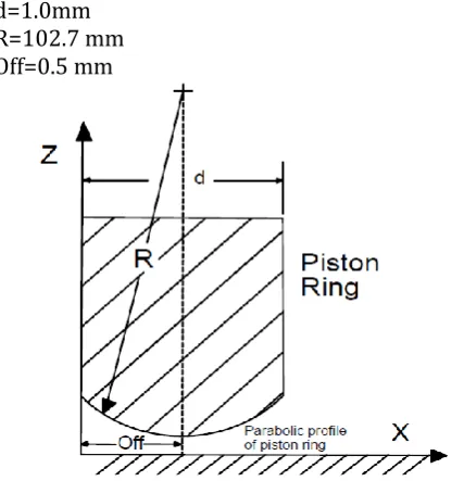
The geometry of the new (unworn) piston ring has been shown in Fig. 2.
d=1.0mm R=102.7 mm Off=0.5 mm
Fig. 2. Unworn piston ring geometry, d-Ring height, R-Radius of the ring surface, Off-offset of the ring sliding surface.
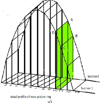
It was decided to measure piston axial ring
profile at 9 angular sections at angle 10o, 450,
900, 1350, 1800, 2250, 2700, 3150, 3500, as
shown in Fig. 3. This way the piston ring is
divided into 8 sectors S1 to S8. The angular positions were marked on the piston ring before beginning of measurements. The piston ring profile is parabolic. To measure the axial profile of piston ring at any angular section, measurement begins with one of the faces of the ring, ‘Ring Face-1’ shown in Fig. 4 and continues up to ‘Ring Face-2. Stylus of ‘Dial Gauge A’ is fixed at point 1 (on piston ring) and scale of dial gauge is adjusted such that ‘zero’ mark of scale coincides with the pointer. Base of the ‘Dial Gauge A’ is mounted on the lathe bed so that the dial gauge A is stationary.
The axial profile readings are taken at 9 sections viz. 100, 450, 900, 1350, 1800, 2250, 2700, 3150
and 3500 angles along the circumference of the
piston ring (Fig. 3).
Fig. 3. Sections 1 to 9 at which the axial profile measurement is taken and sector S1 to S8.
Fig. 4. 13 Axial positions for measurement of piston ring profile.
Piston ring profile along axial width was measured with the help of dial gauge at 13
points as shown in Fig. 4.
3. Experiment and Measurement
The research work focuses on calculating degree of wear at different sectors along the circumference of the top piston ring. Wear of piston ring can be quantified as difference in volumes of a new piston ring and worn out piston ring by measuring the piston ring profile.
3.1 Calculation of wear volume of the piston ring along the circumference
In order to calculate wear volume along the circumference, the piston was divided into eight
sectors S1, S2, S3,S4,S5,S6,S7, S8 as shown in Fig. 3 by way of 9 sections.
a)
b)
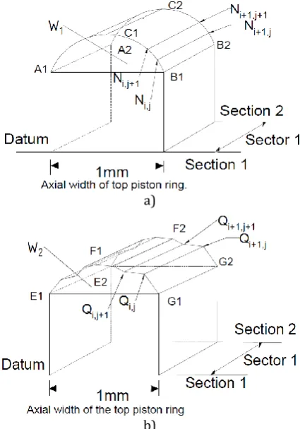
Fig. 5. a) Axial profile of new piston ring, b) Axial profile of worn out piston ring.
Consider sector 1 which is enclosed by section-1 and section-2. Each section on new piston ring as
shown in Fig. 5a is represented by Ni (where i=1 to
9) sections. Thirteen measurements of ring profile were taken along axial direction on section-1.
These measurements are represented by N1,1, N1,2,
..., N1,13 (Ni,j , where i = 1 and j = 1 to 13). Similarly,
points N2,1, N2,2, ..., N2,13 ( Ni,j , where i = 2 and j = 1
to 13) can be identified on section 2.
Analogous points Q1,1, Q1,2, ..., Q1,13 (Qij, where i =
1 and j = 1 to 13) on section 1 and points Q2,1,
Q2,2, ..., Q2,13 (Qij, where i = 2 and j = 1 to 13) can
be identified on section 2 of worn out piston ring
as shown in Fig. 5b.
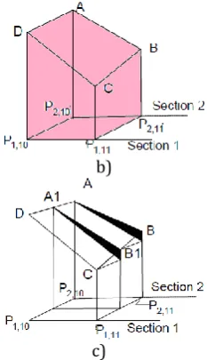
To calculate the volume for any sector of worn out ring, it is assumed that profile between
points Ni,j on section ‘i’ varies linearly up to
corresponding point to Ni+1,j on the subsequent
section ‘i+1’.
curved profile of new piston ring
A1-B1-C1-A2-B2-C2-A1, indicated as W1 (Fig. 5a) and volume
enclosed by the curved profile
E1-F1-G1-E2-F2-G2 indicated as W2 (Fig. 5b) for a sector. Volume
E1-F1-G1-E2-F2-G2 is the volume left over after wear of the piston ring for a sector. The process is repeated for each of the 8 sectors. The process of calculating volume for worn out ring is elucidated in the subsequent text.
Fig. 6. Superimposed profiles of new piston ring and worn piston ring.
Volumetric wear can be calculated by
determining the difference between W1 and W2
(Fig. 6) for each sector.
3.2 Volume calculation for new piston ring (VN)
Methodology adopted to determine volume enclosed between two sections of the new piston ring is illustrated in Figs. 7a and 7b. Profile of new piston ring is measured at 13 equi-distant divisions along axial width of piston ring by dividing each section into 12 equal parts as shown in Fig. 7.
a)
b)
Fig. 7. a) Axial profile of a new piston ring between a sector, b) Highlighted Solid.
Volume of each of the 12 parts is calculated separately. For example, consider two divisions say 10 and 11 between section 1 and 2 respectively, they are P1,10 & P1,11 on section-1 and
correspondingly P2,10 & P2,11 on section-2
(highlighted), on the axial width of the piston ring.
Volume enclosed by profile of piston ring between two points on section-1 and two corresponding points on section-2 is calculated as the volume of the solid ‘P1,10-P1,11-P2,11-P2,10-
P1,10-D-C-B-A-D’ as shown in Fig. 11 (enlarged
view is shown in Fig. 7). The volumes of the 12 axial parts are calculated as above and the volumes are summated to get the total volume
VN,1 of sector-1. The exercise is repeated for
remaining 7 sectors. Total volume of piston ring profile for new piston ring is sum of all eight volumes. (VN, 1 + VN, 2 + ... + VN,8 ) between two
sections (Figs. 3 and 4) on the circumference of the piston ring.
3.3 Volume calculation of wear volume for
worn out piston ring (VW)
Axial profile of worn out piston ring was measured at 13 points in axial direction, at each of 9 sections and the results are tabulated in Table 2. The readings are average of three measurements taken by the dial gauge.
The graphical representation of the axial profile (Table 2) is shown in Fig. 8.
the profile at each section (Fig. 9a). For example, profile between two axial positions 10 and 11 (highlighted) on each section 1 and 2 are shown
in Fig. 9b. The volume enclosed by points ‘P1,10
-P1,11-P2,11-P2,10-P1,10-D-C-B-A-D’ is divided
further into two parts as shown in Fig. 9c.
Fig. 8. Axial profile of worn out piston ring at different sections.
a)
b)
c)
Fig. 9. a) Axial profile of a worn out piston ring between a sector, b) Highlighted Solid,c) Approximated solid for volume calculations.
The volume of each half solid is calculated separately by approximating the volume as trapezoids as shown in Fig. 9c. The volume of solid represented by points ‘P1,10-P1,11-P2,11-P2,10-P1,10
-D-C-B-A-D’ is calculated by summing up the volume of two trapezoids.
Likewise volume has been calculated for all the 12 axial parts on the profiles between two sections.
Volume of sector 1 represented as VW,i is calculated
by taking sum of volume of each of the 12 parts. Total volume enclosed by worn profile in a sector bound by two sections is calculated by summing the volumes of 12 such parts. The volume calculations have been done by a code generated in MATLAB.
Summation of volume of all 8 sectors VW, 1 to VW, 8
gives the total volume of worn piston ring W2.
Table 2. Measurement of profile in micrometers at the 13 points along the axial direction.
Pos. No. 100 (Sec 1)
450
(Sec2)
900
(Sec 3)
1350
(Sec 4)
1800
(Sec 5)
2250
(Sec 6)
2700
(Sec 7)
3150
(Sec 8)
3500
(Sec 9)
1 0 0 0 0 0 0 0 0 0
2 6 10 11 15 6 9 7 16 6
3 11 15 25 25 25 21 20 29 15
4 23 26 40 56 45 40 40 45 35
5 29 52 65 69 79 74 70 78 45
6 34 62 90 90 106 107 112 103 37
7 22 69 95 115 125 120 122 114 26
8 12 60 70 90 110 90 108 105 17
9 8 35 40 75 90 70 72 74 10
10 5 20 25 30 65 40 46 55 6
11 0 10 12 14 40 17 12 29 0
12 0 0 0 0 6 6 5 6 0
Table 3. Sector-wise Percentage wear of worn piston ring.
Sector No.
Bounds of sector (Deg.)
Sector size (Deg.)
Volume of sector of new piston ring
VN,i
(mm3)
Volume of sector of worn piston ring VW,i
(mm3)
Wear Volume of worn piston ring Wi = VN,i -VW,i
(mm3)
Sector-wise Percentage wear
(Pi)
(%)
1 10-45 35 1.32 0.5433 0.774 58
2 45-90 45 1.69 0.699 0.993 59
3 90-135 45 1.69 0.8845 0.808 47.7
5 135-180 45 1.69 1.084 0.569 36
6 180-225 45 1.69 1.103 0.59 35
7 225-270 45 1.69 1.038 0.655 38.7
8 270-315 45 1.69 1.075 0.681 37
9 315-350 35 1.32 0.59 0.73 55.3
4. RESULTS AND DISCUSSIONS
4.1 Wear Volume Analysis
Wear volume at each sector for worn out piston ring is calculated by subtracting volume of each
sector of worn piston ring VW,i from
corresponding volume VN,i of New piston ring
for a sector i.
Wear volume of sector-1 of worn out ring
= Volume of sector - 1 of New piston ring – Volume of sector - 1 of worn out piston ring
Wi = VN,i - VW,i (1)
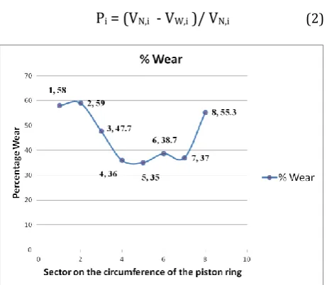
Volumetric wear in each sector can be represented as percentage of volume of new piston ring of the respective sector. The calculations have been shown in Table 3.
Percentage wear of a sector:
Pi = (VN,i - VW,i )/ VN,i (2)
Fig. 10. Wear volume as percentage volume of material in respective sectors of new piston ring.
Fig. 11. Sector wise wear volume in mm3 of piston ring.
The Fig. 10 shows the wear volume of each sector and the size of each sector. As the size of
first and last sector is 35o and that of remaining
sectors is 45o. The volume wear is represented
as percentage of volume of new piston ring for the corresponding sector (Fig. 11).
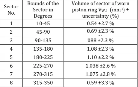
5. UNCERTAINTY ANALYSIS
The wear volume V W, i is calculated by summing
up the volume of 12 solids (Fig. 9b) ‘P1,10-P1,11-
P2,11-P2,10-P1,10-D-C-B-A-D’ between two sections.
The heights of the solids have been measured three times and the average measurement is considered as the true value for calculations.
The standard deviation is taken as the uncertainty in the measurements.
The uncertainty of each volume sector measured is given in Table 4.
Table 4. Sector wise Uncertainty Analysis. Sector
No.
Bounds of the Sector in
Degrees
Volume of sector of worn piston ring VW,I (mm3) ±
uncertainty (%)
1 10-45 0.54 ±2.7 %
2 45-90 0.69 ±2.3 %
%
3 90-135 088 ±2.3 %
4 135-180 1.08 ±2.3 %
5 180-225 1.10 ±2.2 %
6 225-270 1.038 ±2.6 %
7 270-315 1.075 ±2.8 %
8 315-350 0.59 ±3.3 %
It can be observed from Table 2 along with Figs. 10 and 11 that the wear of piston ring is not uniform throughout the circumference. The
wear is bigger near the end gap (10o to 45o and
315o to 350o). Wear is smaller at about 180o
from end gap.
As wear is caused due to friction which is caused due to lack of lubricant, it can be inferred that oil film thickness formed along the circumference is not uniform. It is likely that portion of ring near end gap undergo boundary lubrication for most of the part of stroke whereas the remaining portion of piston ring experiences hydrodynamic lubrication for most of the part of stroke.
6. CONCLUSION
The volume loss due to wear near the end gap(sector 1 and sector 8) is bigger as compared to the other sectors of the piston ring as illustrated in Fig. 10. A non uniform wear pattern has been observed by the above study (Fig. 10) for longer period of stroke. The total
wear loss is the order of 10-9 μm [11].
This leads us to infer that the piston ring experiences boundary lubrication near the end
gap of the piston ring till 450. It experiences
mixed lubrication regime from 450 to 1800 and
from 1350 to 1800 from the centre of the gap it
experiences hydrodynamic lubrication.
The behaviour is symmetrical about the end gap. The piston ring experiences boundary
lubrication from 3500 (near the end gap) till
3150, mixed lubrication from 3150 to 1800 and
hydrodynamic lubrication from 1800 to 2250
(opposite the gap of the piston ring). Due to
severe lubrication conditions occurring close to
TDC, towards the end of the compression and beginning of expansion stroke mixed or boundary lubrication is expected throughout the circumference of the piston ring.
REFERENCES
[1] W.C. Pike, D.T. Spillman, The use of a motored engine to study Piston Ring wear and Engine friction, Proceedings of the Institution of Mechanical Engineers, vol. 178, iss. 14, pp. 37-44, 1963, doi: 10.1243/PIME_CONF_1963_178_374_02
[2] T.H.C. Childs, F. Sabbagh, Boundary-Lubricated Wear Of Cast Irons To Simulate Automotive Piston Ring Wear Rates, Wear, vol. 134, iss. 1, pp. 81-87, 1989, doi: 10.1016/0043-1648(89)90063-X [3] P.C. Nautiyal, S. Singhal, J.P. Sharma, Friction and
Wear processes in piston rings, Tribology International, vol. 16, iss. 1, pp. 43-49, 1983, doi: 10.1016/0301-679X(83)90009-9
[4] M. Priest, D. Dowson, C.M. Taylor, Predictive wear modeling of lubricated piston rings in a diesel engine, Wear, vol. 231, iss. 1, pp. 89-101, 1999, doi: 10.1016/S0043-1648(99)00125-8 [5] S.C. Tung, Y. Huang, Modeling of Abrasive Wear in
a Piston Ring and Engine Cylinder Bore System, Tribology Transactions, vol. 47, iss. 1, pp. 17-22, 2004, doi: 10.1080/05698190490279074
[6] J.J. Truhan, J. Qu, P.J. Blau, The effect of lubricating oil condition on the friction and wear of piston ring and cylinder liner materials in a reciprocating bench test, Wear, vol. 259, iss. 7–12, pp. 1048-1055, 2005, doi: 10.1016/j.wear.2005.01.025 [7] K. Wannatong, S. Chanchaona, S. Sanitjai, Simulation
algorithm for piston ring dynamics, Simulation Modelling Practice and Theory, vol. 16, iss. 1, pp. 127-146, 2008, doi: 10.1016/j.simpat.2007.11.004
[8] M. Kapsiz, M. Durat, F. Ficici, Friction and wear studies between cylinder liner and piston ring pair using Taguchi design method, Advances in Engineering Software, vol. 42, iss. 8, pp. 595-603, 2011, doi: 10.1016/j.advengsoft.2011.04.008
[9] M.A. Bulsara, Measurement of Piston ring wear in an I C Engine: A case study, Indian Journal of Tribology, vol. 5, iss. 1, pp. 32-36, 2010.
[10] E.H. Smith, Optimising the design of a piston-ring pack using DoE methods, Tribology International, vol. 44, iss. 1, pp. 29-41, 2011,
doi: 10.1016/j.triboint.2010.09.002
lubricated contact, Applied Mathematical Modeling, vol. 39, iss. 8, pp. 2234-2260, 2015,
doi: 10.1016/j.apm.2014.10.011 [12] A. Michael, Uncertainity Analysis of a
Multifunctional Tribometer (Master's Thesis). Lehigh University, Pennsylvania, U.S.A., 2017.
NOMENCLATURE
W1
Volume of the new piston ring between a sector, enclosed between two sections,
along the circumference of the piston ring. mm
3
W2
Volume of the worn out piston ring between a sector, enclosed between two sections, along the circumference of the piston ring.
mm3
VN,i Volume of the new piston ring for sector i. mm3
VW,i Volume of the worn out piston ring
sector i. mm3