Published online October 20, 2013 (http://www.sciencepublishinggroup.com/j/ijrse) doi: 10.11648/j.ijrse.20130206.13
Performance evaluation and operation of Auto Load
transfer switch
Diponkar Paul, Md. Shariful Islam, Syed Khalid Rahman, Md. Saiful Islam, Mir Mohiuddin
World University of Bangladesh, Dhaka, Bangladesh
Email address:
[email protected] (D. Paul), [email protected] (M. S. Islam), [email protected] (S. K. Rahman), [email protected] (M. S. Islam), [email protected] (M. Mohiuddin)
To cite this article:
Diponkar Paul, Md. Shariful Islam, Syed Khalid Rahman, Md. Saiful Islam, Mir Mohiuddin. Performance Evaluation and Operation of Auto Load Transfer Switch.International Journal of Renewable and Sustainable Energy. Vol. 2, No. 6, 2013, pp. 205-211.
doi: 10.11648/j.ijrse.20130206.13
Abstract:
An automatic transfer switch is an integral component of an emergency power supply system (EPSS). Auto transfer switch (ATS) consists of different electrical and mechanical components such as magnetic contactor, relay, timer, over under voltage relay etc. Basically maintenance includes scheduled and unscheduled renovation works. Efficiency of auto transfer switch (ATS) can be increased by using proper operation & standard maintenance schedule. Maintenance procedures are normally used to reduce unexpected problems of auto transfer switch. Proper installation, commissioning, operation, maintenance & troubleshooting procedure have been discussed thoroughly in this project report. A large number of real pictures have been shown to make the report more useful to all. It has been tried to provide a good understanding of the ideas about proper operation, maintenance & troubleshooting of auto transfer switch. Some auto transfer switches allow load shedding prioritization of optional circuits, such as heating and cooling equipment. More complex emergency switchgear used in large backup generator installations permits soft loading, allowing load to be smoothly transferred from the utility to the synchronized generators, and back; such installations are useful for reducing peak load demand from a utility. In cases where two independent utility feeders are available, a fast load transfer can be achieved by the use of a static transfer switch. When the critical load includes a load transformer, the transformer is subjected to transients during the transfer interval. Therefore following a load transfer, a transient current flows into the transformer which can cause a post transfer voltage sag. Fault disturbance characteristics which determines voltage difference between the sources and the voltage drop across t he incoming and the outgoing thyristor switches during the load transfer process.Keywords:
ATS, Earthing Bar, AC & DC Timer Base1. Introduction
The application of automatic switches for transferring load, consideration should be given to the relative costs of air break switches versus oil circuit breakers. This is especially true when the circuit or circuits under consideration, at some future date, might become the source for important load centers. It is not the intent of the authors to discuss the costs nor to outline the relative advantages of one type of switching scheme over another. It might be pointed out, however, that automatic air break can be installed readily in such a manner that, when the circuit conditions warrant, oil circuit breakers can be added and the original air break switches used for by-pass switching. The principal function of an automatic load transfer scheme is to transfer a load from a preferred source,
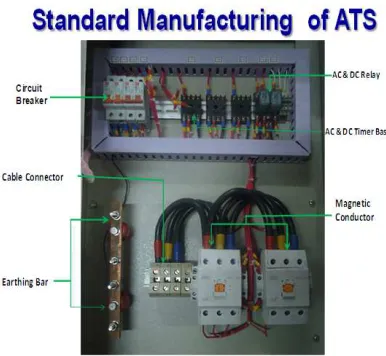
proper knowledge for standard manufacturing and maintenance of ATS such as ATS electrical drawing, design, assembly, electrical connection, improper safety protection, maintenance schedule we are facing several problems after manufacturing of the ATS. But ATS is now one of the most important part for our electricity transmission sector. If we know and consent to maintain standard manufacturing design and maintenance procedure of ATS manufacturing and maintenance works then we will come out from those problems easily. For the sequence our Internship title is Manufacturing of Automatic Transfer Switch. Designing and manufacturing an ATS following different standards [1]. Study on different components those are used in ATS to select appropriate materials, equipments and to ensure proper installation and troubleshooting. Knowing about standard manufacturing process. To understand the assembly procedure of ATS. To identify different types of trouble and necessary measures related with ATS. Suggest possible solution of the identified problem. This report is also have some limitations such like we cannot get the soft copy of datum from the computers of Company for having confidential. So, we lost some data. We also get very little chance to pick the photos because that is a restricted and sensitive area. They don’t allow us to carry cell phones and camera. That why we can gather some photos only from non- restricted part of the company.A transfer switch is an electrical switch that reconnects electric power source from its primary source to a standby source. Switches may be manually or automatically operated. An Automatic Transfer Switch (ATS) is often installed where a backup generator is located, so that the generator may provide temporary electrical power if the utility source fails.
Figure 1: Standard Manufacturing of Automatic Transfer Switch
As well as transferring the load to the backup generator, an ATS also commands the backup generator to start, based on the voltage monitored on the primary supply. The transfer switch isolates the backup generator from the electric utility, when the generator is on and is providing temporary power. The control capability of a transfer switch may be manual only, or a combination of automatic
engine will generally be required to be controlled by an isochronous governor. It is generally required that the closed transition, or overlap time, be less than 100 milliseconds. If either source is not present or not acceptable (such as when normal power fails) the switch must operate in a break-before-make mode (standard open transition operation) to ensure no back feeding occurs. Closed transition transfer makes code-mandated monthly testing less objectionable because it eliminates the interruption to critical loads [3], which occur during traditional open transition transfer. With closed transition transfer, the on-site engine generator set is momentarily connected in parallel with the utility source. This requires getting approval from the local utility company. A soft-loading transfer switch actively changes the amount of load accepted by the generator. A static transfer switch uses power semiconductors such as Silicon-controlled rectifiers (SCRs) to transfer a load between two sources. Because there are no mechanical moving parts, the transfer can be completed rapidly, perhaps within a quarter-cycle of the power frequency. Static transfer switches can be used where a reliable and independent second source of power is available and it is necessary to protect the load from even a few power frequency cycles interruption time, or from any surges or sags in the prime power source.
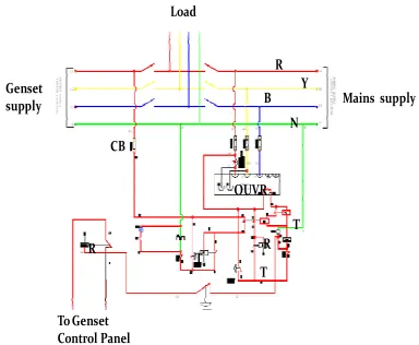
Mains supply Genset
supply
Load
OUVR CB
R Y B
N
T
T R
T R
To Genset Control Panel
Figure 2: Typical load switching application for closed transmission
Typical load switching applications for which closed transition transfer is desirable include data processing and electronic loads, certain motor and transformer loads, load curtailment systems, or anywhere load interruptions of even the shortest duration are objectionable. A closed transition transfer switch (CTTS) is not a substitute for a UPS (uninterruptible power supply); a UPS has a built-in stored energy that provides power for a prescribed period of time in the event of a power failure. A CTTS by itself simply assures there will be no momentary loss of power when the load is transferred from one live power source to another. Homes with standby generators may use a transfer switch for a few circuits or the whole home. Different models are available, with both manual and automatic transfer. Often small transfer switch systems use circuit
the sensitive load. Duration of power discontinuity is the key factor in predicting proper operation of the load. A STS must be able to perform a fast load transfer from the disturbed source to the healthy one regardless of the load type and the fault/disturbance characteristics. Power discontinuity, as a result of load transfer process by means of a STS, is determined by the total load-transfer time (ttot )The total load-transfer time is the sum of 1) detection
time (tdet—delay in voltage detection logic) and 2) transfer
time (ttr—delay in load transfer mechanism). Performance
of a STS, with respect to transfer time, under various fault/disturbance scenarios is investigated in [1] when the sensitive load is represented by a passive RL load. This paper evaluates a STS performance for hybrid (RL + motor) loads. It describes the effects of a regenerative (motor) load on the STS transfer time and explains the relation between fault/disturbance characteristics and regenerative mode of operation of the hybrid load. It also identifies the worst case scenario(s) in which the maximum transfer time can occur. Commutation process in each phase is determined by the following two factors: 1) Voltage drop across the alternate source incoming thyristor switch after the fault/disturbance detection. 2) Direction of the current flow in the corresponding phase. Parameters which affect the commutation process between the thyristor switches, and thus the transfer time, are listed in [1]. These parameters are: Thyristor gating method which is the strategy of removing gating signals from Ti thyristor switches and triggering T2 thyristor switches. Load type, parameters and characteristics which determine the relative positions of phase voltage and line current zero-crossings and the voltage drop across the incoming and the outgoing thyristor switches. Fault/disturbance characteristics which determine voltage difference between the sources and the voltage drop across the incoming and the outgoing thyristor switches during the load transfer process.
2. Methodology
Station L normally is served from station OC which in turn is served from a 69,000-volt transmission line connecting stations OR and P. Oil circuit breakers 488 at station OR and 588 at station P normally are closed and are reclosed manually after automatic tripping. Oil circuit breakers 177 at station OC and 188 at station OR normally are closed with control arranged for one immediate reclosure after automatic tripping and two time delay reclosures. The total r e c l o s i n g c yc l e i s a p p r o x i ma t e l y 2l/ t minutes. At station L motor operated air break switch 152 normally is closed and 252 normally open with their controls arranged for automatic switching. AUTOMATIC SWITCHING FOR FAULT
CONDITIONS.Failure of Line Potential. Failure of voltage on the incoming line from station OC causes, after a time delay of approximately three minutes, the opening of switch 152 followed by the closing of switch 252. This switching is initiated by the de-energized contact of
Therefore, following a load transfer, a transient current flows into the transformer which can cause a post-transfer voltage sag. It is important to design the STS control system to distinguish a post-transfer voltage sag from those due to the feeder disturbances. A post-transfer voltage sag is a function of the transformer parameters (e.g., saturation characteristics, the line impedances, and the transfer process). The transient flux is determined by (1) the load transformer parameters, (2) fault/disturbance characteristics, (3) the time needed for the detection of a disturbance in the system (i.e., detection time), and (4) the time needed for the load transfer (i.e., transfer time). A fast STS was introduced in [4]. The STS employs (1) a voltage detection logic based on transforming ac voltages into a synchronously rotating frame and (2) a selective gating strategy based on the direction of current flow. Performance of the voltage detection logic is reported in [5]. The transfer scheme performance is also evaluated in [6]. In [5] and [6], various disturbances are considered, and the corresponding detection time/transfer time curves are derived. Two utility feeders, one of which is the preferred source and the other one is the alternate source; sensitive load; STS which can connect the load to either of the sources; control system which monitors the quality of the sources voltages, and performs a load transfer if needed. To estimate the transient flux of a load transformer during a transfer process, the single-phase equivalent circuit diagram of a three-phase Delta/Wye transformer is used. Fig. 4 depicts this equivalent circuit. Precise calculation of the transient flux is not trivial due to the complexity of the STS behavior and nonlinearity of the load transformer. To make the analytical expressions manageable, the following simplifying assumptions are made: 1) thyristor switches are ideal; 2) load transformer is linear; 3) utility feeders are in-phase; 4) line impedances are neglected to estimate the peak transient flux; 5) no paralleling occurs between the two feeders. Under normal operating conditions, the transformer is connected to the preferred source. Therefore, if the line impedances are neglected, then where vt is the
transformer input voltage, vp is the preferred- source
voltage, va is the alternate-source voltage, vp is the peak
voltage, and (p is the phase angle. As shown, the power source is given to the electromagnet through a control switch and through contacts to the load. When current starts flowing through the control coil, the electromagnet starts energizing and thus intensifies the magnetic field. Thus the upper contact arm starts to be attracted to the lower fixed arm and thus closes the contacts causing a short circuit for the power to the load. On the other hand, if the relay was already de-energized when the contacts were closed, then the contact move oppositely and make an open circuit. As soon as the coil current is off, the movable armature will be returned by a force back to its initial position. This force will be almost equal to half the strength of the magnetic
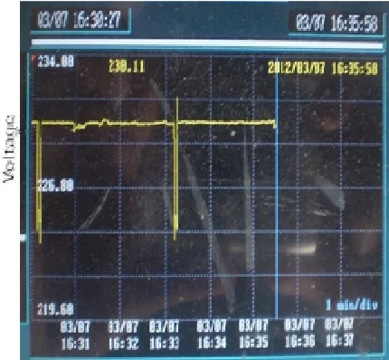
Figure 3: Time versus voltage curve with changing of load demand by voltage control scheme
When load increases, voltage temporarily decreases and for the very short time, voltage offset Created. Auto load transfer switch by voltage control scheme, makes operation stable. Upon loss of power the automatic transfer type station will always transfer itself to its second available source of power provided that second source is energized. The automatic sectionalizing type station will always pick itself up upon whichever line become energized and will close the sections together if both become energized. If a fault occurs on, the bus between the automatic air switches of either transfer type or sectionalizing type, both air switches will, after unsuccessful attempt to re-energize the bus, open and remain open until manual switching is performed. With both switches thus locked open it is evident that all section of the line can be energized from their respective source of power. Our method operation differs in an outstanding point from that of Rich and Kirwen. There is no need of co-ordination of timing between the operation of the breakers and the feed points in the operation of the automatic air switches, except that the breaker should not close until the air break switches have opened [5], that is, the first re closure should not be less than about three seconds. We do not delay the operation of our air-switches until tests are made by the automatic breakers at the source stations. Instead, the transfer type installation at once transfers its load to the second source; the sectionalizing type at once opens both of its air-switches. The action in both cases is initiated by an under voltage time delay relay set to close its contacts in one second at zero volts. The load of the transfer type installation is thus re-energized within three seconds; the load of the sectionalizing installation is energized after an interruption not exceeding about nine seconds. If both line sections become energized, the two air-switches will close restoring the entire line to service in the case of the sectionalizing type of install.
3. Conclusion
switching operations unless they are in synchronism. In the design of automatic air break switch control schemes, the first consideration is the potential source to use for operation and control. Some schemes require a source of potential independent of the lines being switched while others can be operated with duplicate sources. One connected to each of the two main transmission lines. Another important consideration is the completion of a transfer, once it is started or to set up the control so that a transfer will take place when one of the lines is energized. The automatic switching schemes described are for single phase control only- that is, one potential transformer for each line. The use of two potential transformers for ungrounded system or three for grounded systems should be given consideration. Single phase control has been chosen and failure to operate and consequent outage has resulted when line wires have been broken. Additional potential transformers and relay are to then be installed to prevent such failures.
References
[1] F. W. Rich, M. S. Kirwen, (1947) “Automatic control of air switches for line sectionalizing and load transfer, “AIEE transactions, vol# 66, ppno #293-302
[2] Hossein Mokhtari, Sashi B. Dewan, (2001),” Effect of regenerative load on a static transfer switch performance “IEEE transactions on power delivery, vol# 6, No# 4.
[3] H. Mokhtari, M. R. Iravani, S. B. Dewan, “ Bench mark systems for digital computer simulation of a static transfers switch, “ IEEE transactions on power delivery submitted for publication.
[4] H. Mokhtari, “High speed silicon controlled rectifier static transfer switch/ “in IEEE 30TH Annual meeting.
[5] H. Mokhtari, M. R. Iravani, S. B. Dewan, (2003), “ Transient behavior of load transfer during sybcycle bus transfer, IEEE transactions on power delivery, vol# 18, No# 4.