Iranian Journal of Electrical & Electronic Engineering, Vol. 13, No. 4, December 2017 353
A New Non-linear Control of the Four-Leg Inverter with
Decoupled Model and Fast Dynamic Response for PV
Generation Systems
M. Pichan*
(C.A.), E. Heydari** and H. Rastegar*
Abstract: Distributed generation (DG) will play an important role in future power generation systems, especially in stand-alone applications. Three phase four-leg inverter is a well-known topology which can be used as an interface power converter for DGs. Thanks to the fourth leg to provide the neutral path, the four-leg inverter is able to supply balanced loads as well as unbalanced loads. In this paper, the model of a three phase four-leg inverter with the fourth leg inductor in the αβγ reference frame is investigated thoroughly. Afterward, a decoupled model of the four-leg inverter is adopted to establish the proposed control method. Among non-linear control methods, pole-placement method is a famous solution to ensure fast transient response. Hence, in this paper, a pole-placement method via state feedback is proposed to control the output voltage of the four-leg inverter. Using this method, the transient performance of the system can be adjusted well. On the other hand, to guarantee good performance of the control system under steady state condition, a lead compensator is proposed to be used with the pole-placement method. Therefore, the proposed control system not only can provide fast dynamic response but also, it ensures very low steady state error. To validate the superior performance of the proposed control method, simulation and experimental results under various loading condition are provided based on a DSP-based digital control system.
Keywords: Four-Leg Inverter, Pole-Placement Control Method, State Feedback.
1 Introduction1
OWADAYS, distributed generation (DG) have gained a high significance due to many advantages especially no CO2 emission. There are two kinds of DG systems, stand-alone and grid-connected ones where stand-alone system has attracted much attention for some applications like powering remote loads. Among these systems, the usage of photovoltaic (PV) system has increased due to its capability of generating electricity in a very clean, quiet, and reliable way [1-3]. An interface power converter between PV system and
Iranian Journal of Electrical & Electronic Engineering, 2017. Paper first received 20 August 2017 and accepted 18 October 2017. * The authors are with the Department of Electrical Engineering, Amirkabir University of Technology, Tehran, Iran.
E-mails: [email protected] and [email protected].
** The author is with the Faculty of Engineering, Tarbiat Modares University, Tehran, Iran.
E-mail: [email protected]. Corresponding Author: M. Pichan.
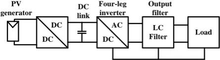
AC loads must supply loads with sinusoidal voltages with fixed amplitude and frequency. According to nature of loads in standalone applications, unbalanced loading condition is inevitable. As a result, for unbalanced loads, the inverter must provide a path for the neutral current. For this purpose, three phase four-leg inverter can be used in which the load neutral is connected to the fourth leg instead of dc-link capacitor midpoint. Compared to other solution for providing neutral current path, the four-leg inverter provides enhanced dc bus utilization, lower ripple on the dc-link voltage and smaller size for dc-link capacitors [4-7].The schematic of stand-alone photovoltaic system is shown in Fig.1 where, the four-leg inverter is equipped with an LC filter.
DC DC
DC
AC LC
Filter Load DC
link
Four-leg inverter
Output filter PV
generator
Fig. 1 Stand-alone photovoltaic system.
N
354 Iranian Journal of Electrical & Electronic Engineering, Vol. 13, No. 4, December 2017 Since three phase four-leg inverter is a suitable
solution for unbalanced/nonlinear loads, the control system play an important task to supply sinusoidal voltage with minimum harmonic distortions. To regulate the load voltages of the four-leg inverter, different research use classic control methods [8-11]. However, most of these methods use frequency domain factors that does not have a precise response in time domain to ensure good transient response [12].On the other hand, other methods such as PI controller shows weak performance in disturbances rejection even while it was properly tuned [13, 14]. Hence, modern control method is essential to adjust the transient response of control system. In addition, it is important to use control method which is robust to against model disturbances and parameters uncertainties. Due to several advantages of the pole placement strategy [15-19], it can be used to control the load voltages of the four-leg inverter. Although this methods was proposed in [19] for the three phase inverter but, the control system is implemented in dq0 reference frame which suffers from different transformations among reference frames and also, high coupling among different d and q components. It is worth to be mentioned that this coupling makes the controller design and performance analysis somewhat complicated. Moreover, in[19], this coupling is completely ignored that decrease the precise of controller design and performance considerably. Furthermore, this method did not present experimental results.
With respect to several benefits of the pole-placement method, this paper proposes a pole-placement strategy via state feedback to control the output voltage of four-leg inverter without any coupling among state variables. By applying this controller, the transient response of control system can be adjusted precisely which is a significant achievement. Furthermore, to guarantee good performance of the control system under steady state condition, a lead compensator is also designed to be used in parallel with the pole-placement method. It is worth to be mentioned that zero steady state error is a very important issue from voltage stability point of view in standalone applications. Moreover, some devices cannot work properly under voltage decrement or increment so, all of these verify the importance of the low steady state error of the control system. Therefore, the proposed control system not only can provide fast dynamic response but also, it ensures very low steady state error. In addition, the proposed method is highly robust against model parameters mismatches.
This paper is organized as follow. The model of the four-leg inverter with a simple decoupling technique is presented in section 2. In section 3, the proposed pole placement control strategy and resonant controller is proposed based on the decoupled model. In section 4 some simulation and experimental results are presented and discussed. Section 5 concludes the paper.
u v w f a b c N P VD C L Ln n iLa iLb iLc in ioa iob ioc C lo ad
Fig. 2 Four-leg voltage source inverter. 2 System modeling
The structure of the four-leg inverter following with the output LC filter and the neutral inductor is shown in Fig.2. As shown in Fig. 2, the load neutral point is connected to the midpoint of the fourth leg through an inductor (LN) which this connection provides a path for
the zero-component of the load current.
For the inverter of Fig.2, each phase voltage with respect to the fourth leg can be defined as:
(1)
uf uN fN
vf DC vN fN
wf wN fN
v d d
v V d d
v d d
where duN, dvN, dwN and dfN are the duty cycles of each
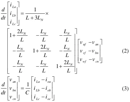
phase according to the negative point of the DC-Link. Now, applying KVL and KCL at the output of the inverter and after some calculations, the state equations of the system are derived as (2) and (3) [20].
(2) 1 3 2 1 2 1 2 1 La Lb N Lc
N N N
uf an
N N N
vf bn
wf cn
N N N
i d
i
dt L L i
L L L
L L L v v
L L L
v v
L L L
v v
L L L
L L L
(3) 1
an La oa
bn Lb ob
cn Lc oc
v i i
d
v i i
dt C
v i i
According to (2), it is clear that there is a coupling between currents of different phases which results in the coupled voltage equations. This coupling makes the analysis and design of the controller a difficult task. To solve the problem, the state equations can be transformed from the abc reference frame to the stationary (αβγ) reference frame [20]. For this purpose, each three phase variable can be transformed from the
abc reference frame to the αβγ reference frame by using the transformation matrix T as defined in (4).
Iranian Journal of Electrical & Electronic Engineering, Vol. 13, No. 4, December 2017 355 (4)
1 1
1
2 2
2 3 3
0
3 2 2
1 1 1
2 2 2
T
By multiplying both sides of (2) and (3) by (4), the state equations in αβγ reference frame are obtained according to (5), (6):
(5) 1 0 0 1 0 0 1 0 0 3
L f n
L f n
L f n
N
L
i v v
d
i v v
dt L
i v v
L L where f f DC f v d
v V d
v d (6) 1
n L o
n L o
n L o
v i i
d
v i i
dt C
v i i
where (vαf,vβf, vγf) and (vαn,vβn, vγn) denote the inverter
and the load voltages in the αβγ reference frame, respectively. According to (5), (6), it is clear that all the state variables are decoupled from each other. Hence, the currents and voltages in the αβγ reference frame can be controlled independently with no effect on each other [20].
3 Proposed Controller
In this paper, the pole placement strategy with state feedback method as one of the modern control method is used to control the system under test. Using this method, the transient performance of the control system
VDC Vαf Vαn iLα ioα Vαn
- 1
-𝐿𝑠 1 𝐶𝑠 1 𝑅𝛼 𝑑𝛼 + VDC Vβf Vβn iLβ ioβ Vβn
- 1
-𝐿𝑠 1 𝐶𝑠 1 𝑅𝛽 𝑑𝛽 VDC Vγ f
Vγn
iLγ ioγ
Vγn
- - 1
𝐶𝑠 1 𝑅𝛾
𝑑𝛾 1
𝑠(𝐿 + 3𝐿𝑛)
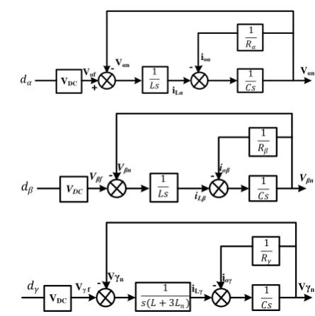
Fig. 3 A signal flow graph of the four-inverter with unbalanced resistive load.
can be adjusted as well as designer requirements. To implement the proposed controller, the state equations in the αβγ reference frame are used since as previously discussed, due to complete decoupling, they can be controlled independently with no effect on each other. Firstly, to consider the general loading condition, an unbalanced resistive load is considered and the state variables is assumed as x = [vαn iLα vβn iLβ vγn iLγ]T.
According to (5) and (6), a signal flow graph of the four-leg inverter is shown in Fig.3. Therefore, the state equations of the system can be concluded as (7). It is worth noting that [Rα, Rβ, Rγ] is the equivalent
resistances matrix of the load in αβγ reference frame. (7)
(t) (t) (t) , (t)
x Ax Bu y Cx
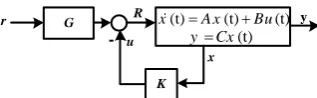
To achieve the desired transient response, the poles of the system can be placed at the appropriate position by proper determination of the feedback matrix K. On the other hand, a lead compensator is also used to track the input reference to guarantee achieving this purpose. The
1 1
0 0 0 0
0 0 0
1
0 0 0 0 0
0 0
1 1
0 0 0 0 0 0 0
, ,
0 0
1
0 0 0 0 0
0 0 0
1 1
0 0 0 0
0 0
3 1
0 0 0 0 0
3 DC n L n DC L n L DC n n CR C V v L L i CR C v
x A B V
i L L v i V CR C L L L L
1 0 0 0 0 0
and 0 0 1 0 0 0 ,
0 0 0 0 1 1
d
C u d
d
356 Iranian Journal of Electrical & Electronic Engineering, Vol. 13, No. 4, December 2017
G
K x R
u
y
r
-(t) (t) (t)
x A x Bu
(t)
yCx
Fig. 4 The structure of the proposed control method with state feedback and lead compensator.
structure of the proposed control method with the state feedback and lead compensator is shown in Fig.4.
3.1 Pole placement via state feedback strategy By considering the state feedback u = -Kx, the closed-loop system equation can be expressed as follow:
(8)
(t)x ABK x
Now, the goal is to find the appropriate matrix K such that the poles of the closed-loop system place on the desired value to suitably improve the transient performance. Applying this method, not only the behavior of the open-loop system can be improved significantly but also, the transient response can be adjusted precisely. Assume the (λ1, λ2, λ3, λ4, λ5, λ6) are
the eigenvalues of the matrix A of the open-loop system and the( ,
ˆ ˆ ˆ ˆ ˆ ˆ1 2, 3, 4, 5, 6)are the desired eigenvalues of the matrix A-BK of the closed-loop system. The characteristic equations of the open-loop and closed-loop system are shown in (9) and (10), respectively:(9)
5 4 0
6
i 1
6 5 4
(s) (s )
...
i
p
sI A
s a s a s a
(10)
5 4 0
6
i 1
6 5 4
ˆ ˆ (s) (s )
...
i
p
sI A BK
s a s a s a
By locating the eigenvalues of the closed-loop system
at( ,
ˆ ˆ1 2,...,
ˆn)and considering the eigenvectors of thesystem as ( , 1 2,...,n), it is concluded that:
(11)
ˆi i i
ABK
and consequently:
(12)
ˆ i 0
i
i
A I B K
Now, by definition qi Ki for i = 1,2,…,n, the following equations are obtained:
(13)
ˆ i 0
i
i
A I B q
(14)
11 2 ... n 1 2 ... n
K q q q
According to (13), the matrix
i qi
T must be placed in the null space of the matrixAˆiI B. Hence, the selection of the eigenvectors is limited by (13) while eigenvalues can be placed at anywhere of the plane. It is worth to be mentioned that due to large variation of the loading condition of the four-leg inverter, the control method should not affected under any single/three phase linear/non-linear loads. In addition, with respect to the variation of the inductors and capacitors during the time, the control method should be robust against model parameter mismatches. As a result, in this paper, eigenvalues placement is done based on a proposed algorithm in [21] in which, it is suitable for multi-input systems and optimizes the choice of eigenvectors for robust operation of the control method.3.2 Design of the lead compensator
By using the pole placement method that is discussed in previous section, the dynamic performance of the system will be tuned precisely. However, the good steady state performance of the system may not satisfied completely. As a result, the lead compensator is adopted to better input reference tracking of the proposed method. According to Fig.4, the input of the system can be expressed as (15).
(15) uGrKx
now, substituting (15) in (7) will results in (16):
(16)
( )
x Ax B GrKx
To ensure zero steady state error, the lim (t) 0
tx , so:
(17) 1
1
( ) ,
( )
x A BK BGr y Cx C A BK BGr
Furthermore, for input reference tracking, lim (t) r
ty ,
hence, the lead compensator can be designed properly as follow:
(18)
1( ) 1
G C ABK B
Applying the complete control system, not only the transient response is adjusted properly but also, the steady state performance will be adjusted to have a zero steady state error in the load voltages. It is two main achievements of the proposed control system which candidate it as one of the best solutions to control the load voltages of the four-leg inverters.
4 Performance Evaluation
To evaluate the general performance of the proposed
Iranian Journal of Electrical & Electronic Engineering, Vol. 13, No. 4, December 2017 357 control system, several simulations are done in
Matlab/Simulink software. Also, a 3kW test bench is provided to validate the simulation results through experimental results. The parameters of the system is shown in Table 1.
The photograph of the test bench is shown in Fig. 5. Due to several benefits of the digital signal processors (DSPs) such as several peripherals, six enhanced PWM channels, sixteen high frequency analog to digital (A/D) converters and high speed calculations ability, the control system is implemented by prototype control board based on the TMS320F28335 DSP from TI company. Also, the SKM100FB12T4 IGBTs are used for the power devices which their gate signals are prepared by the prototype board with HCPL316J ICs. The low pass LC filter connected at the inverter output is responsible to remove or decrease the switching ripples. It is appreciate assumption to set the cut-off frequency of the LC filter at 10% of the switching frequency [20]. The current ripple of the inductor at the worst case is given in (19) [22]:
(19) Inductor Current Ripple
* (1 ) 2 * * sw
V DC
D D
L F
where D is defined as the line to neutral duty ratio. According to the maximum allowable current ripple, the
L is selected from (19). Afterward, based on the cut-off frequency, the proper value for C is calculated. To achieve the best performance from Load voltage THD point of view [23], the neutral inductor (Ln) is selected
as half of the three phase inductors (L).
Table 1 The parameters of the system.
Parameter Description Value
Vo Nominal output voltage 100v (rms)
fo
Nominal output voltage
frequency 60Hz
fsw Switching frequency 12kHz
VDC DC-Link voltage 390v
Lf Filter inductance 880 µH
Cf Filter capacitance 33 µF
LN Neutral filter inductance 440 µH
DSP-Based Digital Control Board
DC-Link Capacitors IGBT-Driver Boards
IGBTs
Filter Inductors
Fig. 5 The photograph of the test bench.
Due to increased number of switching vectors of the four-leg inverter (24=16) compared to three leg
inverters, the common SVM PWM method is somewhat complex for digital implementation [24-26]. On the other hand, the sinusoidal PWM method not only provides good harmonic profile but also, it provides considerably simple structure [27]. Therefore, the SPWM method is adopted in this paper to generate the switching gate signals.
Substituting the parameters of the system in (9), the eigenvalues of the open-loop system are obtained as
1,2 1893 5699j
,3,4 1515 5812 j ,5,6
1262 3526j
. The desired eigenvalues of the
closed-loop system are selected as ˆ1,2 49836 3913 j ,
0.005 0.01 0.015 0.02 0.025 0.03 0.035 0.04 0.045 0.05 -150
-100 -50 0 50 100 150
time(s)
Lao
d
Volt
age
(V)
van vbn vcn
(a)
(b)
(c)
(d)
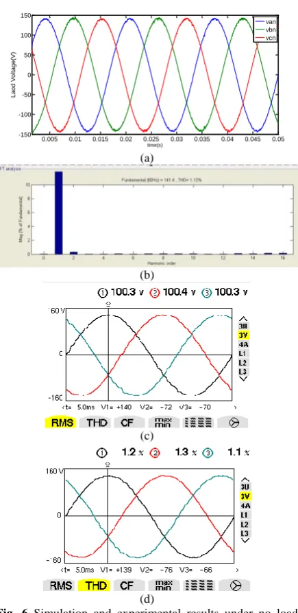
Fig. 6 Simulation and experimental results under no load condition; simulation results: a) phase voltages, b) THD% of the phase voltages; experimental results: c) phase voltages, d) THD% of the phase voltages.
358 Iranian Journal of Electrical & Electronic Engineering, Vol. 13, No. 4, December 2017 3
ˆ 30000
,
ˆ4 50000,
ˆ5 80000,
ˆ6 80000.By locating the eigenvalues of closed-loop system
at( ,
ˆ ˆ ˆ ˆ ˆ ˆ1 2, 3, 4, 5, 6), the transient performance of the control system can be adjusted well. On the other hand, a lead compensator is also designed for better input reference tracking by (18).In the first study, the four-leg inverter is tested under no load condition and both simulation and experimental results are shown in Fig. 6. As evidently appears, the control system tracks the reference values precisely. The total harmonic distortion (THD%) of the load voltages under simulation results is 1.13% which shows that the simulation and experimental results are in good accordance with each other.
Non-linear loads have been used widely in both high
a b c
n
R R C
R=44Ω C=120µF
R C
C
Fig. 7 The structure of the non-linear load.
(a)
(b)
(c)
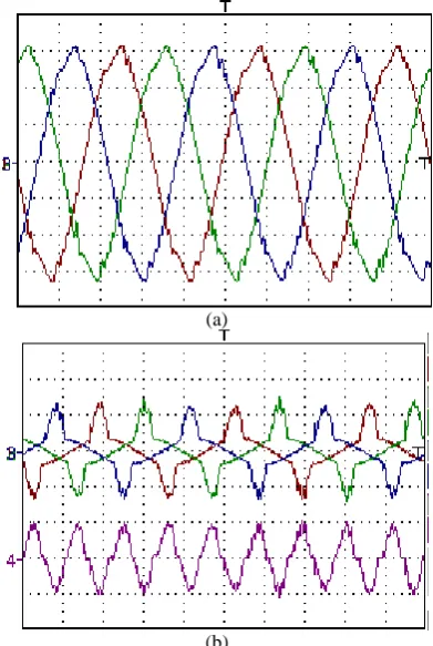
Fig. 8 The experimental results under non-linear loads: a) voltage (50 v/div) and current (13 A/div) of phase 'a', b) load voltages, c) THD% of the load voltages.
power industrial applications such as adjustable AC drives and low power domestic applications such as electronic ballasts and switching power supplies. Since these loads absorb high harmonic polluted currents, the inverter should maintain its normal operation under any non-linear loading condition. To evaluate the performance of the four-leg inverter with proposed control method, three phase non-linear load as depicted in Fig. 7 is connected at inverter outputs and the results are shown in Fig. 8.
Based on Fig. 8 (a), it is evident that even with large harmonic polluted and sharp current, the load voltage does not affected much. At this condition, the maximum THD% of the load voltages is 3.6% which is much lower than 8% so, the performance under non-linear load satisfies the IEC62040-3 international standard. The voltage reference tracking error
o,reference o,measured o,reference
( [%]ev (V V ) / V 100) is below 1.4%.
To better evaluate the performance of the proposed control system, a hybrid load involving both linear and non-linear loads are connected at inverter outputs and the results are shown in Fig. 9. The THD% of the load voltages are 2.8% under this condition with ev% equal to 3%.Since the amount of non-linear loads are decreased, the THD% of the phase voltages are improved while, due to increase of loads, the reference tracking error experienced a bit increment.
(a)
(b)
Fig. 9 Experimental results under hybrid linear/non-linear loads: a) phase voltages; ch1-ch3 (50 v/div), b) phase (ch1-ch3) and neutral currents (ch4) (13 A/div).
Iranian Journal of Electrical & Electronic Engineering, Vol. 13, No. 4, December 2017 359 As one of the achievements of the proposed control
system, the transient response can be adjusted precisely. To examine this characteristic, the transient waveforms
(a)
(b)
Fig. 10 Experimental results under step changes of the load: a) falling and b) rising step changes; phase voltages: ch1-ch3 (100 v/div), phase 'b' current (ch4) (13 A/div).
-500 -40 -30 -20 -10 0 10 20 30
1 2 3 4 5
ev% THD%
∆L% (a)
-500 -40 -30 -20 -10 0 10 20 30
1 2 3 4 5
ev% THD%
∆C% (b)
Fig. 11 Experimental evaluation of the robustness of the control system under model parameter mismatches: a) filter inductors mismatches, b) filter capacitor mismatches.
in response to the no-load to nominal resistive load step change (rising) and also falling step change are shown in Fig. 10. With respect to this figure, the control system retrieves the load voltage in a time interval lower than 400 μs. Since the load step change is performed near the peak value of the phase 'c' (ch3 with green color) voltage, it experiences the most severe condition from voltage drop point of view. However, the control system compensates the voltage error with a small undershoot of about 12% of the nominal voltage.
In another study, the effect of parameter mismatches on the control performance is considered. According to Fig.3 and (7), the filter inductors and capacitors, L and
C, are the most usable parameter in the control system. Therefore, the performance of the proposed controller in response to mismatches in these parameters is studied in terms of the THD% and the ev%. The results are shown
in Fig.11.
Based on Fig. 11, it can be concluded that the control system maintains its normal operation even under large model parameter mismatches.
5 Conclusion
In power converter interface between DG systems and AC loads, to supply unbalanced/non-linear loads, three phase four-leg inverter with the neutral inductor seems to be the best solution. To achieve the benefits of the four-leg inverter as well as providing clean sinusoidal balanced voltages, control system plays an important task. In this paper, to provide adjustable transient response precisely, a pole-placement strategy via state feedback with no coupling between the state variables is proposed to control the output voltages of the four-leg inverter. In addition, a lead compensator is also designed for precise tracking of the reference input. Several simulation and experimental results were performed to investigate the performance of the proposed control methods. All of these verify the effectiveness of the proposed method where the transient response under 100% step load changing is below 2ms. Also, the THD% value of the load voltages at sever non-linear loading condition is below 3.6% which satisfies the IEC62040-3 international standard. Furthermore, it is confirmed that the proposed control method is highly robust against model parameter mismatches.
References
[1] G. S. Ilango, P. S. Rao, A. Karthikeyan, and C. Nagamani, “Single-stage sine-wave inverter for an autonomous operation of solar photovoltaic energy conversion system,” Renewable Energy, Vol. 35, pp. 275-282, 2010.
360 Iranian Journal of Electrical & Electronic Engineering, Vol. 13, No. 4, December 2017 [2] A. Mellit, M. Benghanem, and S. Kalogirou,
“Modeling and simulation of a stand-alone photovoltaic system using an adaptive artificial neural network: Proposition for a new sizing procedure,” Renewable Energy, Vol. 32, pp. 285-313, 2007.
[3] B. Singh and S. Sharma, “Design and implementation of four-leg voltage-source-converter-based VFC for autonomous wind energy conversion system,” IEEE Transactions on Industrial Electronics, Vol. 59, pp. 4694-4703, 2012.
[4] S. Bifaretti, A. Lidozzi, L. Solero, and F. Crescimbini, “Modulation With Sinusoidal Third-Harmonic Injection for Active Split DC-Bus Four-Leg Inverters,” IEEE Transactions on Power Electronics, Vol. 31, pp. 6226-6236, 2016.
[5] X. Guo, R. He, J. Jian, Z. Lu, X. Sun, and J. M. Guerrero, “Leakage current elimination of four-leg inverter for transformerless three-phase PV systems,” IEEE Transactions on Power Electronics, Vol. 31, pp. 1841-1846, 2016.
[6] V. Yaramasu, M. Rivera, M. Narimani, B. Wu, and J. Rodriguez, “Model Predictive Approach for a Simple and Effective Load Voltage Control of Four-Leg Inverter With an Output Filter,” IEEE Transactions on Industrial Electronics, Vol. 61, pp. 5259-5270, 2014.
[7] M. Zhang, D. J. Atkinson, B. Ji, M. Armstrong, and M. Ma, “A near-state three-dimensional space vector modulation for a three-phase four-leg voltage source inverter,” IEEE Transactions on Power Electronics, Vol. 29, pp. 5715-5726, 2014.
[8] D. De and V. Ramanarayanan, “A proportional multiresonant controller for three-phase four-wire high-frequency link inverter,” IEEE Transactions on Power Electronics, Vol. 25, pp. 899-906, 2010. [9] G. H. Kim, C. Hwang, J. H. Jeon, J. B. Ahn, E. S.
Kim,”A novel three-phase four-leg inverter based load unbalance compensator for stand-alone microgrid,” International Journal of Electrical Power & Energy Systems, Vol. 65, pp. 70-75, Feb. 2015.
[10]R. A. Gannett, “Control strategies for high power four-leg voltage source inverters,” Virginia Polytechnic Institute and State University, 2001. [11]J. Liang, T. C. Green, C. Feng, and G. Weiss,
“Increasing voltage utilization in split-link, four-wire inverters,” IEEE Transactions on Power Electronics, Vol. 24, pp. 1562-1569, 2009.
[12]G. Thandi, R. Zhang, K. Xing, F. C. Lee, and D. Boroyevich, “Modeling, control and stability analysis of a PEBB based DC DPS,” IEEE Transactions on Power Delivery, Vol. 14, pp. 497-505, 1999.
[13]L. Sun, D. Li, K. Hu, K. Y. Lee, and F. Pan, “On tuning and practical implementation of active disturbance rejection controller: a case study from a regenerative heater in a 1000 MW power plant,”
Industrial & Engineering Chemistry Research, Vol. 55, pp. 6686-6695, 2016.
[14]L. Sun, D. Li, and K. Y. Lee, “Enhanced decentralized PI control for fluidized bed combustor via advanced disturbance observer,” Control Engineering Practice, Vol. 42, pp. 128-139, 2015. [15]H. M. Kojabadi and L. Chang, “Comparative study
of pole placement methods in adaptive flux observers,” Control Engineering Practice, Vol. 13, pp. 749-757, 2005.
[16]B. Li, W. Yao, L. Hang, and L. Tolbert, “Robust proportional resonant regulator for grid-connected voltage source inverter (VSI) using direct pole placement design method,” IET Power Electronics, Vol. 5, pp. 1367-1373, 2012.
[17]B. Li, M. Zhang, L. Huang, L. Hang, and L. M. Tolbert, “A new optimized pole placement strategy of grid-connected inverter with LCL-filter based on state variable feedback and state observer,” in
Applied Power Electronics Conference and Exposition (APEC), 2013 Twenty-Eighth Annual IEEE, 2013, pp. 2900-2906.
[18]L. A. Maccari, H. Pinheiro, and R. C. Oliveira, “Robust pole location with experimental validation for three-phase grid-connected converters,” Control Engineering Practice, Vol. 59, pp. 16-26, 2017. [19]R. Nasiri and A. Radan, “Pole-placement control of
4-leg voltage-source inverters for standalone photovoltaic systems: Considering digital delays,”
Renewable Energy, Vol. 36, pp. 858-865, 2011. [20]M. Pichan, H. Rastegar, and M. Monfared,
“Deadbeat control of the stand-alone four-leg inverter considering the effect of the neutral line inductor,” IEEE Transactions on Industrial Electronics, 2016.
[21]J. Kautsky, N. K. Nichols, and P. Van Dooren, “Robust pole assignment in linear state feedback,”
International Journal of Control, Vol. 41, pp. 1129-1155, 1985.
[22]M. Pichan, A. Ale Ahamad, A. Arishamifar, M. E. Jamarani,”A Straightforward Procedure to Select Passive Elements in Single-phase Pulse-width Modulation Rectifiers with Developed Resonant Current Controller,” Electric Power Components and Systems, Vol. 44, No. 4, pp. 379-389, Feb 2016. [23]M. Pichan, H. Rastegar, “Sliding Mode Control of
Four-Leg Inverter with Fixed Switching Frequency for Uninterruptible Power Supply Applications,”
IEEE Transactions on Industrial Electronics, Vol. 64, No. 8, pp. 6805-14, Mar. 2017.
Iranian Journal of Electrical & Electronic Engineering, Vol. 13, No. 4, December 2017 361 [24]F. Hasanzad, H. Rastegar, G. B. Gharehpetian, M.
Pichan, “Space Vector Modulation Technique to Reduce Leakage Current of a Transformerless Three-Phase Four-Leg Photovoltaic System,”
IJEEE, Vol. 13, No. 2, pp. 142-151, Apr. 2017. [25]X. Li, Z. Deng, Z. Chen, and Q. Fei, “Analysis and
simplification of three dimensional space vector PWM for three-phase four-leg inverters,” IEEE Transactions on Industrial Electronics, Vol. 58, No. 2, pp. 450–464, Feb. 2011.
[26]A. Mohd, E. Ortjohann, N. Hamsic, W. Sinsukthavorn, M. Lingemann, A. Schmelter, and D. Morton, “Control strategy and space vector modulation for three-leg four-wire voltage source inverters under unbalanced load conditions,” IET Power Electronics, Vol. 3, No. 3, pp. 323–333,May 2010.
[27]D. Fernandes, F. Costa, and E. dos Santos, Jr., “Digital-scalar PWM approaches applied to four-leg voltage-source inverters,” IEEE Transactions on Industrial Electronics, Vol. 60, No. 5, pp. 2022– 2030, May 2013.
M. Pichan received his B.S. in Electronics Engineering from University of Isfahan, Isfahan, Iran, in 2010. He finished his M.S. in electrical engineering at Amirkabir University of Technology, Tehran, Iran, in 2012. He received his PHD degree in electrical engineering at Amirkabir University of Technology, Tehran, Iran, in
2017. He is currently Assistant Professor at the Iranian Research Institute of Electrical Engineering working on medium and high power converters design. His research interests include rectifiers, inverters, and power electronics and their applications in renewable energies.
E. Heydari received her B.S in Electrical Engineering from university of Razi, Kermanshah, Iran, in 2012. She finished her M.S in Electrical Engineering at Shahid Beheshti University, Tehran, Iran, in 2015. She is currently working toward her Ph.D at Tarbiat Modares University. Her research interests include power electronics and its applications in renewable energies.
H. Rastegar was born in Gorgan in 1962.
He received the B.Sc., M.Sc., and Ph.D. degrees in Electrical Engineering from the Amirkabir University of Technology, Tehran, Iran, in 1987, 1989, and 1998, respectively. Currently, he is a Professor at Amirkabir University of Technology. He has published many papers in journals and conferences. His research interests include power system control, application of computational intelligence in power systems, Simulation and Analysis of Power Systems, and Renewable Energy.