RESEARCH NOTE
VISUAL PATTERN IMAGE CODING BY
A MORPHOLOGICAL APPROACH
S. Saryazdi
Shahid Bahonar University of Kerman, Kerman, Iran, [email protected]
V. Haese-Coat and J. Ronsin
Laboratoire ARTIST, Institut National des Sciences Appliquées 20 Avenue des Buttes de Coësmes, 35043 Rennes Cedex, France
haese_coat@insa_rennes fr ronsin@insa_rennes.fr
(Received: October 6, 2000 – Accepted in Revised Form: October 7, 2002)
Abstract This paper presents an improvement of the Visual Pattern image coding (VPIC) scheme presented by Chen and Bovik in [2] and [3]. The patterns in this improved scheme are defined by morphological operations and classified by absolute error minimization. The improved scheme identifies more uniform blocks and reduces the noise effect. Therefore, it improves the compression ratio and image quality is steel preserved. To achieve a better compression ratio, a hierarchical approach based on the merging of uniform blocks is also described. Experimental results show that the improved scheme provides higher compression ratios compared to ordinary VPIC.
Key Words Image Compression, Visul Pattern Image Coding, Mathematical Morphology
ﻩﺪﻴـﻜﭼ
ﻩﺪﻴـﻜﭼ
ﻩﺪﻴـﻜﭼ
ﻩﺪﻴـﻜﭼ
ﻲﻳﺎﻨﻴﺑﻱﺎﻫﻮﮕﻟﺍﺯﺍﻩﺩﺎﻔﺘﺳﺍﺎﺑﺮﻳﻮﺼﺗﻱﺭﺍﺬﮔﺪﻛﺵﻭﺭﻪـﻟﺎﻘﻣﻦـﻳﺍﺭﺩ )
VPIC
( ﻥﺎﻳﺎﻗﺁﻂﺳﻮﺗﻩﺪﺷﻪﺋﺍﺭﺍ
Bovik
ﻭ Chen
ﺎﺑﺲﭙﺳﻭﻒﻳﺮﻌﺗﻱﮊﻮﻟﻮﻓﺭﻮﻣﺕﺎﻴﻠﻤﻋﻂﺳﻮﺗﻪﺘﻓﺎﻳﺩﻮﺒﻬﺑﺵﻭﺭﺭﺩﺎﻫﻮﮕﻟﺍﻢﻴـﻫﺩﻲـﻣﺩﻮﺒـﻬﺑﺍﺭ
ﺪﻧﻮﺷﻲﻣﻱﺪﻨﺑﻪﺘﺳﺩ،ﻖﻠﻄﻣﺭﺪﻗﻱﺎﻄﺧﻱﺯﺎﺳﻢﻤﻴﻨﻴﻣﺭﺎﻴﻌﻣ
. ﻪﺑﻙﻮﻠﺑﻱﺮﺘﺸﻴﺑﺩﺍﺪﻌﺗﻲﺋﺎﺳﺎﻨﺷﻪﺑﺮﺠﻨﻣﺵﻭﺭﻦﻳﺍ
ﺖـﺧﺍﻮﻨﻜﻳﻥﺍﻮﻨـﻋ
)
ﻲﻠﺻﺍﺵﻭﺭﻪﺑﺖﺒـﺴﻧ
(
ﺩﺩﺮﮔﻲﻣﺰﻳﻮﻧﺮﺛﺍﺶﻫﺎﻛﻦﻴﻨﭽﻤﻫﻭ
.
ﺍﺮﺑﺎﻨﺑ
ﻱﺯﺎﺳﻩﺩﺮﺸﻓﺐﻳﺮﺿﻦﻳ
ﺮﻳﻮﺼﺗﺖﻴﻔﻴﻛﻪﻛﻲﻟﺎﺣﺭﺩﺪﺑﺎـﻳﻲـﻣﺶﻳﺍﺰـﻓﺍﺮﻳﻮـﺼﺗ
)
ﻲﻠﺻﺍﺵﻭﺭﻪﺑﺖﺒﺴﻧ
(
ﺖﺳﺍﻩﺪﻳﺩﺮﮔﻆﻔﺣﻥﺎﻨﭽﻤﻫ
.
ﺭﺩ
ﻱﺎﻬﻛﻮﻠﺑﻡﺎﻏﺩﺍﺱﺎﺳﺍﺮﺑﻲﺒﺗﺍﺮﻣﻪﻠﺴﻠﺳﺵﻭﺭﻚﻳ،ﺮـﺗﻻﺎﺑﻱﺯﺎـﺳﻩﺩﺮـﺸﻓﺐﻳﺮـﺿﻪـﺑﻲـﺑﺎﻳﺖـﺳﺩﻱﺍﺮـﺑﻪـﻣﺍﺩﺍ
ﺩﺩﺮﮔﻲﻣﻪﺋﺍﺭﺍﺭﻭﺎﺠﻣﺖﺧﺍﻮﻨﻜﻳ
.
ﺵﻭﺭﻪﻛﺪﻨﻫﺩﻲﻣﻥﺎﺸﻧﻲﻠﻤﻋﺞﻳﺎﺘﻧ ﻱﺮﺗﻻﺎﺑﻱﺯﺎﺳﻩﺩﺮﺸﻓﺐﻳﺮﺿﺯﺍﻩﺪﺷﻪﺋﺍﺭﺍ
ﺖﺳﺍﺭﺍﺩﺭﻮﺧﺮﺑﻲﻠﺻﺍﺵﻭﺭﻪﺑﺖﺒﺴﻧ
)
ﻦﻴﺑﻲﺸﻳﺍﺰﻓﺍ ٤٧
ﺎﺗ ٧١ ﻲﺒﺗﺍﺮﻣﻪﺴﻠﺳﻢﺘﻳﺭﻮﮕﻟﺍﺩﺭﻮﻣﺭﺩﺪﺻﺭﺩ
.(
1. INTRODUCTION
In the framework of very low bit-rate image coding techniques, there is an increasing interest in second generation image compression techniques [1]. Such techniques eliminate redundant information by making use of the properties of the human visual system. Chen and Bovik [2-5] have recently proposed a second generation image compression
coding process takes into account the intensity gradient magnitude,
∇
b=
∆
x
2+
∆
y
2 , and the orientation gr adient,∠∇
=
−
∆
∆
x
y
tan
1b ,
where
∆
x
and∆
y
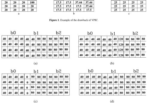
represent respectively the mean difference between the right hand half-block and the left hand half-block and mean difference between the top block and the bottom half-block. Then it classifies each block as uniform or non-uniform according to the gradient magnitude. If the intensity gradient magnitude is lower than a predetermined threshold, the block is considered as uniform, otherwise it is associated with a pattern according to the gradient orientation,quantized in 45° increments, and to the number of pixels of an intensity greater than the mean intensity of the block. So, the pattern selection is not motivated by mathematical criteria such as minimization of local error norms. The visual patterns have zero mean intensity and unit gradient magnitude and are image independent. The mean intensity is quantized using 6+1 bits for the uniform blocks and 4+1 bits for the non uniform blocks, where the additional bit indicates the block type. If the block is considered as non uniform, the index of its related pattern and its gradient magnitude are quantized using 3 and 3 bits respectively. Finally, the edge polarity is also coded by 1 bit. Therefore, 12 bits are needed to 20 20 20 20 17.5 37.44 37.44 37.44 25 25 25 25 20 20 20 100 17.5 17.5 37.44 37.44 25 25 25 25
20 20 20 20 17.5 17.5 17.5 37.44 25 25 25 25
20 20 20 20 17.5 17.5 17.5 17.5 25 25 25 25
a b c
Figure 1. Example of the drawback of VPIC.
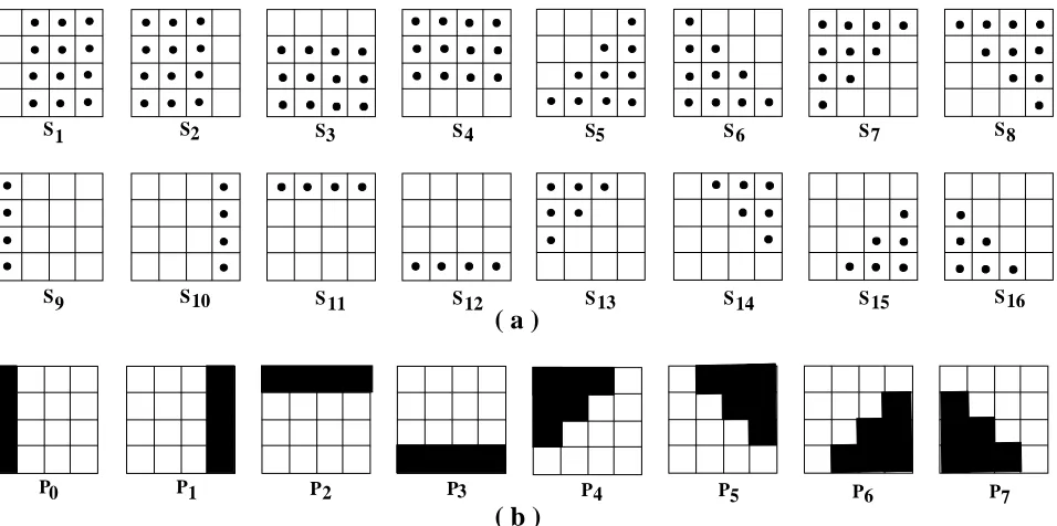
80 40 40 40 40 40 40 40 40 40 40 40 40 40 40 40 40 40 40 40 40 40 40 40 40 80 80 80 80 80 80 80 80 80 80 80 80 80 80 80 80 80 80 80 80 80 80 80 40 40 40 40 40 40 40 40 40 40 40 40 40 40 40 40 40 40 40 40 40 40 40 40 120 80 80 80 80 80 80 80 80 80 80 80 80 80 80 80 80 40 40 40 40 120 120 120 (a) (b) 80 40 40 40 40 40 40 40 40 40 40 40 40 40 40 40 40 80 80 80 80 80 80 80 80 80 80 80 80 80 80 80 80 80 80 80 80 80 80 80 80 80 80 80 0 0 0 0 40 40 40 40 40 40 40 40 40 40 40 40 40 40 40 40 40 40 40 40 40 40 40 40 80 80 80 80 80 80 80 80 80 80 80 80 80 80 80 80 80 80 80 80 40 40 40 40 (c) (d) Figure 2. Comparative examples of ordinary VPIC and proposed scheme, (a) three successive blocks containing a vertical edge, (b,c)
code a non uniform block. So the compression ratio depends on the number of uniform blocks. Unlike most other image codinge schemes, VPIC does not use any mathematical criteria such as minimization of error norms. So, the pattern defined by intensity gradient introduces two important drawbacks to this coding scheme which is due to the fact that the intensity gradient depends mainly on the intensity variation and not on the real geometric features of the block :
1. a pattern is related to a block for which the intensity gradient is greater than a threshold without considering its geometric features, so it is sensitive to noise. For example, in the uniform block shown in Figure 1 one pixel is corrupted by noise. This noisy pixel will
introduce errors to each pixel in the block. 2. if for a block the intensity gradient is zero, it
will be considered as a uniform block. So, all symmetric blocks will be detected as uniform regardless to their geometric features. Examples of such blocks are illustrated in Figure 2-a. Recently, there has been a great interest in morphological filters in coding applications [6-9]. Morphological filters [10] exploit geometric structures in images and, therefore, are efficient in cases where compression of geometric visual information is required. In this paper, we will improve the visual pattern image coding scheme by using morphological operations. We will describe the improved scheme in the next section and present the coding results in section 3.
2. IMPROVED VISUAL PATTERN CODING
A. Coding Process
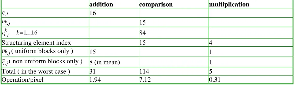
In the improved VPIC, the image to be coded is first pre-processed by using directional closing [12] by the four structuring elements of size 5 shown in Figure 4. This operation removes the isolated pixels of low( a )
( b )
S
0
1 2 3 5 6 7 8
9 10 11 12 13 14 15 16
S S S S S S S
S
S S S S S S S
4
P P1 P2 P3 P4 P5 P6 P7
Figure 3. (a) Structuring element set used in improved VPIC, (b) Pattern set of ordinary VPIC.
intensity without degrading visual quality. The pre-processed image
I
=
{ }
I
i,j is then divided intonon-overlapping blocks of size 4×4 of the form
[
I
:
4
i
n
4
i
3
,
4
j
m
4
j
3
]
b
i,j=
m,n≤
≤
+
≤
≤
+
. Eachblock is designated by its minimal intensity
m
i,j and its residual blockr
i,j:)) n , m ( j , i b ( j , i
m =
min
m,n (2 - 1))
b
supp(
)
l
,
k
(
,
m
)
l
,
k
(
b
)
l
,
k
(
r
i,j=
i,j−
i,j∈
i,j (2 - 2) Hence, the residualr
i,j is always positive.In our approach, the pattern set is replaced by a set of N binary structuring elements of a size smaller than or equal to 4×4, all centred at (0,0), e.g. the structuring elements set of Figure 3-a. Note that here, contrary to the ordinary VPIC, one can define the symmetric structuring elements as well. Each block is related to the structuring element which minimizes the absolute error. It should be noted that among the criteria of the form of a P-norm minimizing
L
P(
E
)
≤ ≤∞P
0 , the
minimum absolute error criterion (P=1) best matches the properties of the human visual system [11]. Once the residual block
r
i,j has beencomputed, the value of its erosion by each structuring element at (0,0),
e
ki,j is calculated:N
,...,
2
,
1
k
)
)
n
,
m
(
B
)
n
,
m
(
r
(
e
ik,j=
i,jΟ
k (m,n)=(0,0)=
(2 - 3) where
Ο
represents morphological erosion. The structuring element providing the minimal absolute error (MAE) is then considered as the structuring element adapted to blockb
i,j, where :
=
×
−
=
∑
=else
0
0
=
B
if
1
S
where
)
n
,
m
(
S
e
)
n
,
m
(
r
MAE
k k j , i 3 0 n , m k j , i k j , i j , i k j , imin
(2 - 4)
The following proposition provides a faster method for determining the structuring element related to
b
i,j.Proposition 1
(
e Cardinal(S ))
to equivalent is ) n , m ( S e ) n , m ( r k j , i k j , i k 3 0 n , m k j , i k j , i j , i k
max
min
× × −∑
=Proof From
)) n , m ( r ( ) ) n , m ( B ) n , m ( r ( e j , i ) B ( Supp ) n , m ( ) 0 , 0 ( ) n , m ( k j , i k j , i
min
k ∈ = = Ο = ,for the points (m,n) such that (m,n)∈Supp(Bk), 0 ) n , m ( S e ) n , m (
r ki,j
k j , i k j ,
i − × ≥ . Hence
× − × −
∑
∑
∑
= = = 3 0 m,n k i,j k i,j 3 0 m,n k i,j k 3 0 m,n k i,j k i,j i,j k (m,n) S e (m,n) r = (m,n) S e (m,n) rmin
min
On the other hand, (bi,j(m,n)) n , m min j , i
m = and
) b supp( ) l , k ( , m ) l , k ( b ) l , k (
ri,j = i,j − i,j ∈ i,j , imply
that )ri,j(m,n is non negative for the points )
n , m
( such that (m,n)∈Supp(Bk), therefore
(
e Cardinal(S ))
) n , m ( S e ) n , m ( S e ) n , m ( r k j , i k j , i k k j , i k j , i n , m k 3 0 n , m k j , i k j , i j , i k
max
max
min
× = × ⇔ × −∑
∑
= .In improved VPIC, the uniform blocks and the non uniform blocks are coded by a different number of bits. If the erosion e of the block by ki,j
considered as a uniform block, otherwise it is non uniform.
If b is a uniform block, its mean intensity i,j m i,j
is quantized and transmitted through the communication channel using nu =nmu+1=7 bits, where the additional bit (flag bit ) indicates the block type.
For a non uniform block, its mean intensity
j , i
m is quantized using nme= 4 bits (nme≤nmu). The index of the selected structuring element is coded by ns=log2(N) bits and finally r over i,j
the support of the selected structuring element r i,j
is quantized using ner= 3 bits, thus to transmit a
non uniform block, ne =ner+nme+ns+1 bits are required, whereas, to code a uniform block
7 1 n
nu = mu+ = bits are needed (nu ≤ne). The
compression ratio CR obtained depends on the image to be coded. For images coded with 8 bits (intensity between 0 and 255), CR is limited to:
u
e n
8 16 CR n
8
16× ≤ ≤ × .
To see how our structuring element selecting method differs from pattern selecting of ordinary VPIC, let us consider the two following examples. The first example shows how the proposed algorithm overcomes the drawback of ordinary VPIC illustrated in Figure 1-b. Note that e takes ik,j
a zero value for structuring elements of the reference set in Figure 3-a. Thus, the block to be coded is considered as uniform block and the reconstructed block will be that of Figure 1-c. This illustrates the two advantages of our algorithm compared to ordinary VPIC: 1. the reduction of noise effect, and 2. the greater number of identified uniform blocks over given image to be coded.
Another comparative example is demonstrated in Figure 2. Figure 2-a shows three successive blocks, of an image containing a vertical edge. The two outer blocks, called b0 and b2, are uniform and
will be identified as uniform by either ordinary or proposed schemes. The block named b1, has a
gradient magnitude of 40, a gradient orientation of 0° (∇I=40,∠I=0), and a mean value of 60. Also, there are 8 pixels within b1 with a grey level
greater than the mean intensity, 60. Thus, either P 1
or P ( negative of 0 P0) could be considered as convenient VPIC patterns (see Figure 3-b). Two possible reconstructed blocks are illustrated in Figure 2-b and c. Obviously, the edge is displaced by one pixel and a discontinuity between two neighbouring blocks is produced. Now, let us see what happens with the proposed algorithm. e is ki,j
maximum for k = 10, thus, S10 will be selected. The reconstructed blocks are illustrated in Figure 2-d. Here, however the edge is still displaced by one pixel, but the continuity between the blocks is preserved.
B. Hierarchical Structure
The previous section shows that the compression ratios of the improved scheme cannot exceed 18.3. One way to increase compression ratios is to increase the block size. However, this will degrade the visual quality of the decoded image. The hierarchical structure presented in the following can increase the compression ratio without degrading image quality.The hierarchical structure consists of merging the suitable uniform blocks, obtained by an improved VPIC scheme, into uniform blocks of size 8×8. That is to say, if the four blocks of size 4×4
2 N ,... 2 , 0 j , i for , b , b , b ,
bi,j i+1,j i,j+1 i+1,j+1 = − are
uniform, and if the difference between the mean intensity of each of them is smaller than a threshold T (here T has been chosen equal to 8), they will be merged into a uniform block of size 8×8. In addition, a flag bit is used to indicate that a 8×8 block b must be considered as a uniform block i,j
of size 8×8 or as four blocks of size 4×4 .
If bi j, is a uniform block, its mean intensity is coded using nu8= 6 bits, otherwise, it is first
divided into four 4×4 sub-blocks bki,j, k=1,...,4, each sub-block is then coded as described in 2-A. Thus the overall bit rate, for coding an image of size M×M by the hierarchical version is :
2
4 e 4 e 4 u 4 u 8 u 8 u 2
M
n N n N n N ) 64 M
(
+ × + × + ×
bits/pixel where Nui and nui are respectively the number of
number of allocated bits. Ne4 and ne4 represent the number of edge blocks and their relative number of allocated bits respectively, and, M2/64 is the number of flag bits.
C. Coding Complexity
Analysis The process of determining the structuring element adapted for the block b consists of the 4 following steps : i,jStep 1 Group the structuring elements according to their support cardinal, so each group contains the structuring elements with the same support cardinal.
Step 2 Calculate eki,j, k=1,...,N, where N is the number of structuring elements
Step 3 Compare e related to each structuring ki,j element in every group, and choosing the largest in each group
Step 4 The results of step 3 are then multiplied by their relative cardinals, and the index of the structuring element providing the best result (or minimal absolute error) is calculated.
Hence, the necessary operations for coding a 4×4 block by improved VPIC, using the structuring elements set of Figure 3-a, are those shown in Table 1. The additional complexity of the hierarchical version comparing to the improved VPIC comes only from the block merging process which necessitates five comparisons for each 8×8 block. Thus, the overall complexity of hierarchical version is 1.94 addition operations, 7.12 comparisons
and 0.31 multiplications per pixel (as opposed to 2.25 additions, 0.53 comparisons and 0.19 multiplications for an ordinary VPIC).
3. EXPERIMENTAL RESULTS AND COMPARISONS
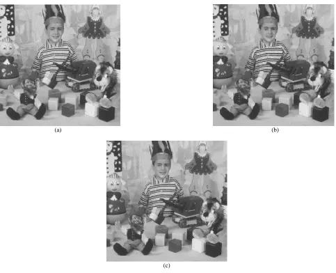
Several experiments are made, and, the results obtained from the image, Kid, is presented below. The image has 512 ×512 pixels and 256 gray levels. The four previously described algorithms (VPIC, HVPIC, improved VPIC and improved hierarchical version) are applied to this image. The structuring elements set in Figure 3-a and the pattern set in Figure 3-c are used for improved VPIC and VPIC respectively. As a pre-processing step, a directional closing by the four linear structuring elements of Figure 4, is applied to the images to be coded by both improved VPIC and hierarchical structure. In VPIC, the gradient magnitude thresholds are ∇Imax =90 and
min
I
∇ =13. For both improved VPIC and the hierarchical version, emin is chosen as 18.
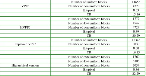
The coded images by VPIC and improved version are illustrated in Figure 5. The images obtained by HVPIC version is similar to those of ordinary VPIC, so it is not presented here. The improved VPIC provides a greater number of uniform blocks than an ordinary VPIC, and a compression rate increment of 6.5% for Kid was TABLE 1. Coding Complexity for a 4××××4 Block of the Improved VPIC.
addition comparison multiplication
ri j, 16
mi j, 15
ei jk, k=1 16,..., 84
Structuring element index 15 4
mi j, ( uniform blocks only ) 15 1
ri j, ( non uniform blocks only ) 8 (in mean) 1
Total ( in the worst case ) 31 114 5
obtained. The improved hierarchical scheme merged 53% of the uniform blocks. So, the improved hierarchical scheme achieves a compression ratio of 22.29 for Kid, which corresponds to an increment of 38% compared to ordinary VPIC and 10% compared to ordinary HVPIC. Table 2 compares the compression ratios obtained by each of the four algorithms. Obviously, the two proposed methods provide a higher compression rate than the ordinary VPIC and HVPIC with an equivalent visual quality.
4. CONCLUSIONS
In this paper, we have proposed the use of morphological erosion, instead of the discrete gradient, to generate visual pattern image codes. We have replaced the pattern set by a set of binary structuring elements. The minimal absolute error has been used as a criterion for the structuring
element selection. The main advantages of this improved VPIC compared to the ordinary VPIC are its fidelity and its higher compression rate. In addition, we have proposed a hierarchical version that provides a higher compression rate for the same visual quality without increasing complexity. These techniques have been experimented on several images and the results yield a compression ratio increment of 47 to 71% compared to the ordinary VPIC.
5. REFERENCES
1. Kunt, M., Ikonomopoulus, A., Kocher, M.,
“Second-Generation Image-Coding Techniques”, Proceedings of
IEEE, Vol. 73, No. 4, (1985), 549-574.
2. Chen, D., Bovik, A. C., “Visual Pattern Image Coding”,
IEEE Trans. on Communications, Vol. 38, No. 12, (1990), 2137-2145.
3. Chen, D., Bovik, A. C., “Hierarchical Visual Pattern
Image Coding”, IEEE Trans. on Communications, Vol.
40, No. 4, (1992), 671-675.
TABLE 2. Comparison of the Coding Results Obtained by the Four Algorithms Described Applied to “Kid”.
Number of uniform blocks 11655
VPIC Number of non uniform blocks 4729
Bit/pixel 0.53
CR 15.16
Number of 8×8 uniform blocks 1777 Number of 4×4 uniform blocks 4547
HVPIC Number of non uniform blocks 4729
Bit/pixel 0.39
CR 20.29
Number of uniform blocks 13345
Improved VPIC Number of non uniform blocks 3039
Bit/pixel 0.50
CR 16.15
Number of 8×8 uniform blocks 1760 Number of 4×4 uniform blocks 6305 Hierarchical version Number of non uniform blocks 3039
Bit/pixel 0.36
4. Silsbee, P. L., Bovik, A. C., Chen, D., “Visual Pattern
Image Sequence Coding”, IEEE Trans. on Circuits and
Systems for Video Technology, Vol. 3, No., (1993), 291-301.
5. Craievich, D., Bovik, A. C., “Stereo Image Compression
Using VPIC”, Proceedings of International Conference
on Image Processing,Vol. 2, Lausanne, Switzerland, (1996), 879-882.
6. Salambier, P., “Morphological Multi-Scale Segmentation
for Image Coding”, Signal Processing, Vol. 38, (1994),
359-386.
7. Salambier, P., Torres, L. Meyer F. and Gu, C.,
“Region-Based Video Coding Using Mathematical Morphology”,
Proceeding of IEEE, Vol. 83, No. 6, (1995), 843-857. 8. Saryazdi, S., Haese-Coat, V. and Ronsin, J., “Image
Representation by a New Optimal Non-Uniform
Morphological Sampling”, Pattern Recognition, Vol.
33, (2000), 961-977.
9. Wang, D., Labit, C. and Ronsin, J., “Segmentation-Based Motion Compensated Video Coding Using
Morphological Filter”, IEEE Trans. On Circuit and
System for Vidio Technology, Vol. 7, No. 3, (June 1996), 549-555.
10. Sternberg, S. R., “Grayscale Morphology”, Computer
Vision, Graphics, and Image Processing 35, (1986), 333-355.
11. Devor, R. A., Jawerth, B., Lucier, B. J., “Image Compression
through Wavelet Transform Coding”, IEEE Trans. on
Information Theory, Vol. 38, No. 2, (1992).
12. Stevenson, R. L. and Arce, G. R., “Morphological
Filters: Statistic and Further Syntactic Properties”, IEEE
Trans. on Circuits and Systems, Vol. CAS-34, No. 11, (1991), 538-598.
13. Netravali, A. N., Haskell, B. G., “Digital Picture Representation and Compression”, Plenum Press, New York, (1988).
(a) (b)
(c)