NUMERICAL SIMULATION OF EFFECTS OF A NON-IONIZED
FLUID INJECTION AND SUCTION ON THE MHD FLOW IN A
CIRCULAR CHANNEL
*
Department of Mechanical Engineering, Urmia University, Urmia, P. O. Box 57169-33111, Iran [email protected]@[email protected]
[email protected][email protected]
*Corresponding Author
(Received: January 02, 2011 – Accepted in Revised Form December 15, 2011)
doi:10.5829/idosi.ije.2012.25.01a.07
Abstract Control of a fluid flow velocity profile by injection and suction of a non-ionized fluid in presence of a uniform steady magnetic field has important technical applications. In this paper, the unsteady incompressible and viscous conducting fluid flow has been investigated in a circular channel. The channel walls are assumed to be non-conducting and porous. They are subjected to a uniform steady magnetic field which is perpendicular to the axis of channel, then and suction and injection are applied at the walls. The well known equations of Magnetohydrodynamics are governed to the motion of an electrically conducting fluid flow that is subjected to magnetic field. The numerical solution is carried out by finite difference approach. The results of present numerical simulation shown that the flow injection and suction through the wall can be controlled effectively, the main flow in channel especially in industrial purposes. The results are obtained for different values of the injected and sucked non-ionized flow rate and the effect of Hartman number on the velocity profile is investigated. Finally, a good agreement is seen between the presented results and the corresponding data of finite element method.
هﺪﯿﮑﭼ
نﺎﯾﺮﺟ ﺖﻋﺮﺳ ﻞﯿﻓوﺮﭘ لﺮﺘﻨﮐ لﺎﯿﺳ
ﺶﮑﻣ و ﻖﯾرﺰﺗ ﻪﻠﯿﺳﻮﺑ ﮏﯾ
ﺪﯿﻣ رﻮﻀﺣ رد هﺰﯿﻧﻮﯾ ﺮﯿﻏ نﺎﯾﺮﺟ ا
ن
دراد ﯽﻤﻬﻣ ﯽﻨﻓ يﺎﻫدﺮﺑرﺎﮐ ،ﻢﺋاد ﺖﺧاﻮﻨﮑﯾ ﯽﺴﯿﻃﺎﻨﻐﻣ .
ﻞﺑﺎﻗ ﺮﯿﻏ ،زﻮﮑﺴﯾو يﺎﻧﺎﺳر لﺎﯿﺳ نﺎﯾﺮﺟ ،ﻪﻟﺎﻘﻣ ﻦﯾا رد
ﺖﺳا ﻪﺘﻓﺮﮔ راﺮﻗ ﯽﺳرﺮﺑ درﻮﻣ يوﺮﯾاد لﺎﻧﺎﮐ ﮏﯾ رد ﻢﺋاد ﺮﯿﻏ و ﻢﮐاﺮﺗ .
هراﻮﯾد هﺪﺷ ضﺮﻓ ﻞﺨﻠﺨﺘﻣ و ﻖﯾﺎﻋ لﺎﻧﺎﮐ
ﺖﺳا . ﺎﯾﺮﺟ ﻖﯾرﺰﺗ و دراد راﺮﻗ ﺖﺳا دﻮﻤﻋ لﺎﻧﺎﮐ رﻮﺤﻣ ﺮﺑ ﻪﮐ ﺖﺧاﻮﻨﮑﯾ ﻢﺋاد ﯽﺴﯿﻃﺎﻨﻐﻣ ناﺪﯿﻣ ﮏﯾ ضﺮﻌﻣ رد ن
هراﻮﯾد رد ﺶﮑﻣ و ﺎﻫ
ﯽﻣ لﺎﻤﻋا دﻮﺷ . يﺎﻧﺎﺳر لﺎﯿﺳ ﮏﯾ ﺖﮐﺮﺣ ﺮﺑ ﯽﺴﯿﻃﺎﻨﻐﻣ ﮏﯿﻣﺎﻨﯾدورﺪﯿﻫ فوﺮﻌﻣ تﻻدﺎﻌﻣ
د راﺮﻗ ﯽﺴﯿﻃﺎﻨﻐﻣ ناﺪﯿﻣ ضﺮﻌﻣ رد ﻪﮐ ﯽﮑﯾﺮﺘﮑﻟا ﺪﻨﺘﺴﻫ ﻢﮐﺎﺣ ،درا
. دوﺪﺤﻣ فﻼﺘﺧا هﺎﮔﺪﯾد ﻂﺳﻮﺗ يدﺪﻋ ﻞﺣ
ﺖﺳا ﻪﺘﻓﺮﮔ ترﻮﺻ .
ﯽﻣ نﺎﺸﻧﺮﺿﺎﺣ يدﺪﻋ ﻞﺣ ﺞﯾﺎﺘﻧ ﯽﻣ هراﻮﯾد رد ﺶﮑﻣ و ﻖﯾرﺰﺗ نﺎﯾﺮﺟ ﻪﮐ ﺪﻫد
نﺎﯾﺮﺟ ﺪﻧاﻮﺗ
يﺮﺛﻮﻣ رﻮﻃ ﻪﺑ ار لﺎﻧﺎﮐ زا يرﻮﺒﻋ ﯽﻠﺻا ﯽﺘﻌﻨﺻ فاﺪﻫا ياﺮﺑ
دراد ﯽﺘﻌﻨﺻ يﺎﻫدﺮﺑرﺎﮐ هﺪﯾﺪﭘ ﻦﯾا ﻪﮐ ﺪﻨﮐ لﺮﺘﻨﮐ .
ﯾدﺎﻘﻣ ياﺮﺑ ﺞﯾﺎﺘﻧ ﺑ ﯽﺸﮑﻣ و ﯽﻘﯾرﺰﺗ نﺎﯾﺮﺟ خﺮﻧ توﺎﻔﺘﻣ ﺮ
ﻪ ﻞﯿﻓوﺮﭘ يور ﺮﺑ ﻦﻤﺗرﺎﻫ دﺪﻋ ﺮﯿﺛﺎﺗ و هﺪﻣآ ﺖﺳد
ﺖﺳا ﻪﺘﻓﺮﮔ راﺮﻗ ﯽﺳرﺮﺑ درﻮﻣ ﺖﻋﺮﺳ .
ﺖﯾﺎﻬﻧ رد ، نﺎﯿﻣ ﯽﺑﻮﺧ ﻖﻓاﻮﺗ نآ ﺮﻇﺎﻨﺘﻣ ﺞﯾﺎﺘﻧ و ﺮﻈﻧ درﻮﻣ هﺪﺷ ﻪﺋارا ﺞﯾﺎﺘﻧ
نﺎﻤﻟا شور زا هدﺎﻔﺘﺳا ﺎﺑ هﺪﻫﺎﺸﻣ دوﺪﺤﻣ
ﺖﺳا هﺪﺷ .
Nomenclature
MHD Magnetohydrodynamics
B0 uniform static magnetic field (Tesla) Rem magnetic Reynolds number
Re Reynolds number
μ Dynamic viscosity (N.s/m2)
1. INTRODUCTION
Recent years have been marked by dramatic advances in active flow control, but developments have had little effect on conducting fluids moving in magnetic fields. MHD is that part of the mechanics of continuous media which studies the motion of electrically conducting media in the presence of a magnetic field. MHD is essential in
ρ Density (kg/m )3
Keywords Magnetohydrodynamics flow; Numerical simulation; Circular channel; Fluid injection; Fluid suction; CFD.
plasma physics and astrophysics and was mainly created by Alfven [1] around 1940 (Nobel prize in physics 1970). In nature, systems in which MHD effects are important include: the Earth’s core and solar flares; and in the engineering world: the electromagnetic casting of metals and the confinement of plasmas [2]. Another area of much interest is fusion engineering; reactor designs commonly involve the use of electrically conducting liquid metals [3]. On the other hand, flow through channels is of paramount importance in many industrial applications. One can mention for example that flow through nozzles, diffusers and reducers as encountered in polymer processing operations. Therefore, in this paper, MHD flow in circular channel has been investigated.
The uses of advanced finite difference, finite element and other semi-analytical and numerical hybrid solvers have resolved many lingering problems in classical viscous flows of electrically-conducting fluids. In this paper, the numerical solution has been carried out by finite difference approach.
Many profound studies have been communicated in the past several decades. Snyder [4] analyzed MHD flows in the entrance region of a rectangular channel and provided a good bibliography of the earlier work. Shercliff [5] examined the steady motion of an electrically conducting, viscous fluid along channels in the presence of an imposed transverse magnetic field when the walls do not conduct currents. K. S. Sai, injection on an incompressible laminar flow in a rectangular duct with non-conducting walls in the presence of an imposed transverse magnetic field. They obtained analytical solutions for the velocity and magnetic field, which are useful for obtaining the current density and electric field strength. Singh and Lal [7] studied the unsteady MHD flow through a pipe having arbitrarily conducting walls using finite elements, for various Hartmann numbers and wall conductivities at various time levels, showing that an increase in wall conductivity or Hartmann number induces a a mathematical model to predict the velocity profile for a unidirectional, incompressible and steady flow of an Oldroyd 6-constant fluid. The fluid was made electrically conducting by a transverse magnetic field, and the developed
governing equation was non-linear. This equation had been solved analytically to obtain the general solution. Also, the governing non-linear equation had been solved numerically subject to appropriate boundary conditions (three cases of typical plane shearing flows) by an iterative technique with the finite-difference discretizations. Hazem Ali Attia [9] studied the unsteady Hartmann flow of a dusty viscous incompressible electrically conducting fluid under the influence of an exponentially decreasing pressure gradient without neglecting the ion slip. The parallel plates had been assumed to be porous and subjected to a uniform suction from above and injection from below. An analytical solution for the governing equations of motion had been obtained to yield the velocity distributions for both the fluid and dust particles.
In this research, the unsteady incompressible and viscous conducting fluid flow has been investigated in a circular channel. The channel wall has been assumed to be non-conducting and porous. It has been subjected to a uniform static magnetic field which is vertical to the axis of channel and suction and injection have been applied at the wall. Hence in this work, for solving the problem, finite difference method has been applied to the unsteady incompressible and viscous conducting fluid flow.
devoted to the basic equation of motion and of the numerical solution are validated. Section 4 deals with the results of the numerical solution and
2. EQUATIONS OF MOTION AND FORMULATION OF THE MODEL
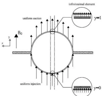
We next consider the unsteady viscous and incompressible conducting fluid flow past a non-conducting and porous circular channel in the presence of a uniform static magnetic field. The circular channel is divided into two equal parts. Fluids are injected with a velocity, v0, at lower half
cylinder and sucked with the same velocity at upper half cylinder; the geometry of the problem as shown in Figure (1).
For comfortable mathematical modeling, we consider an infinitesimal element to formulate the problem; the selected elements are depicted in Figure (2).
This paper is organized as follows: s ection 2 is formulation of the model. In section 3, the results
section 5 gives the conclusions. et al. [6] examined the effects of suction or
Figure 1.Schematic of the model
Figure 2. Cross-section of the model with selected infinitesimal elements
With these considerations, we formulate the unsteady flow through a non-conducting and porous parallel plate channel in the presence of a uniform static magnetic field that (x, y) are Cartesian coordinates and B0 is a uniform static
magnetic field in y-direction. The two independent velocity components are u(in x-direction) and v(in
y-direction).
For either laminar or turbulent flow, the two-dimensional continuity equation is given by:
u v
0
x y
(1)
Momentum differential equation can be written as:
V p f dt dV
b
2
(2)
where, fb is a body force. One can neglects gravity
body force (fb,y) in y-direction ,but there is a
magnetic body force fb,x on the x-direction and is
called Lorenz force [10, 11]; that its relation is given by:
B J force
Lorenz (3)
The (J) stands for the electric current density, and (B) is the magnetic flux, respectively. We obtain the current density from Ohm’s law [10, 11]:
E V B
J (4)
where, (σ) is the electrical conductivity and
E is the electric field. Motion of an electrically conducting fluid in an applied magnetic field would induce a magnetic field in the medium. The total field is, therefore, the sum of the applied and induced magnetic fields. The relative strength of the induced field is characterized by the magnetic Reynolds number (Re =m mUL with characteristic values of velocity and length, U and L, and mismagnetic permeability). One can assume that the induced magnetic field is negligible. This assumption is justified when the magnetic Reynolds number is small. Since no external electric field is applied and the effect of polarization of the ionized fluid is negligible, we can also assume the electric field is zero, so that:
0
E (5)
Substituting this expression into Eq. (4) and its result in Eq. (3), yields:
V B
B B Vfbx
2 0
, (6)
We assumed that a static magnetic field with a constant magnetic flux density B0is applied in the y-direction.
Momentum differential equation in x-direction for this problem is given by:
2 2
2 2 2
0 1
y u x
u u B x p
y u v x u u t u
(7)
and sucked with the same velocity at upper half cylinder, hence, the velocity in y-direction is assumed to bev0. According to this assumption:
0
0
y v v v (8)
Substituting Eq. (8) into continuity equation, one gets:
,
u
0 u u y t
x
(9)
Due to the fact that the velocity in x-direction is a function of yand t, then:
2u x = 02
(10)
Substituting Equations (8), (9) and (10) into Eq. (7), brings:
2 2
0
0 2
1 B
u u p u
v u
t y x y
(11)
Also, Momentum equation in y-direction is introduced by:
2 2 2 2
1
v v v p v v
u v
t x y y x y
(12)
Because of v=v0, then: 0 2 2 2 2 y v x v y v x v t v (13)
Substituting Eq. (13) into Eq. (12), one obtains:
0 y p (14)
Combining Equations (14) and (11), it would be found that:
) (t p x p
(15)
It is expedient to write the Eq. (11) in the non-dimensional form. To do this, we introduce the following non-dimensional quantities:
* 0 , u u v
* 0
, v t t L * , y y L * , x x L * 2 0 , p p v
2 02
0 , L B Ha v
Re v L0 ,
Eq. (11) reduces to:
* 2 2 * * 2 * * * * * * Re 1 u Ha y u x p y u t u (16)
The velocity distribution can be evaluated from the no-slip boundary condition at the upper and lower walls:
* *
u 0,t = 0
* *
u 1,t = 0 (17)
Also, initial condition for this problem is assumed as:
* *
u y ,0 = 0 (18)
According to Equation (15), p t( )cte is considered for simplicity in mathematical computation. 3. VALIDATION 2 * * * 2 2 * * 2 * * * * * * 1 Re 1 u N u u Ha y u x p y u t u F (19)
In the computations, the pressure gradient is decomposed into a steady component and an imposed (oscillatory) part such that:
* * 0 * s pp p coswt x
that is:
where, λis Darcian linear drag parameter andNFis
Forchheimer second-order parameter. More simplest case; steady, non-magnetic, non-porous flow is considered (p0=0, ps=10, Ha=0, λ=∞, NF=0). They computed the influence of Reynolds
number on velocity profiles.
With these assumptions, Eq. (19) would be change into Eq. (16) and these results can be compared together.
u* versus y* has been plotted for Re=3 and Re=5. Whereupon, the comparison of finite element results with the corresponding curves obtained by finite difference method show good agreement.
* *
* *
4. NUMERICAL SOLUTION AND RESULTS
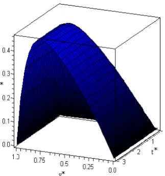
For solving the differential equation (Eq. 16), the provided and utilized. In this research, the Taylor-series expansion is utilized to approximate, and discretization of the equations are carried out with implicit method. This method is usually unconditionally stable. ,The results of this solution are presented in this section. Dimensionless velocity surface as function of y*and t*is shown in Figure (4), that is for Re=10, Ha=1 and p(t)=1. As can be seen in this figure, profile of u* is asymmetric at about the plan y*=0.5 because of the injection and suction, and maximum velocity occurs at almost *
Figure 4. The velocity profile in the surface with Re=10, Ha=1 and p(t)=1.
* *
been plotted for Ha=1, 3, 5; at all three state, velocity profile changes from t*=0 to t*=1.5 and after that it does not change with time (in fact the profile attains steady state at *
Ha=3 and Ha=5, where steady state has occurred at t*=0.4 and t*=0.7, respectively. It can be realized from the above-mentioned diagrams that the time to achieve steady state would decrease with growing of Hartman number.
explanation is available in the literature [12]. For the
code for finite difference method has been
Figure 3a.u versus y for Re=3
Figure 3b.u versus y for Re=5
In Figures (5a), (5b) and (5c), u versus y has
Re=10 and p(t)=1. While Ha=1 (Figure 5a),
t=1.5). Figures (5b) and (5c) is plotted for
In Figures (3a) and (3b),
* * *
with Ha=1, Re=10 and p(t)=1.
* * *
with Ha=3, Re=10 and p(t)=1.
* * *
with Ha=5, Re=10 and p(t)=1.
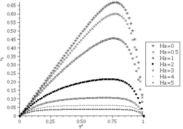
When profile does not change withtime, effect of y* on the u* is shown for different Hartman numbers in Figure (6). All of these profiles are varied for Re=10 and p(t)=1. From this figure, it is clear that with increasing Ha, maximum velocity would decrease. In high Hartman numbers no velocity profile would exist. The maximum value of these indicated profiles is seen to happen at
y*=0.75. Thus the location of the maximum velocity is independent of the Hartman number.
Figure 6.Effect of y*on the u*for various values of Hartman number with Re=10 and p(t)=1.
Figure (7) illustrates the effect of different Reynolds numbers at Ha= p(t)= 1, and profile does not change in terms of time). As seen in this figure at low Reynolds numbers the velocity profile is symmetric about the plan y*=0.5, but maximum velocity would take place toward y*=1 with increasing of Reynolds number. Thus, the location of the maximum velocity is dependent on the Reynolds number.
Figure 7. Effect of versus various values of Reynolds number on the u*with Ha=1 and p(t)=1.
Figure 5a. u versus y for various values of t
Figure 5b. u versus y for various values of t
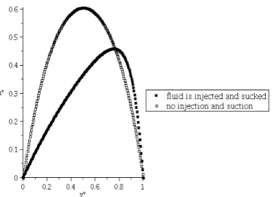
The change of velocity profiles due to impose of injection and suction mechanism is gathered in Figure (8); that is one of the most goals of present investigation. Both profiles are formed since
Re=10, p(t)=1 and Ha=1. From this results it is evident that when injection and suction do not exist, profile is symmetric about the plan y*=0.5, but maximum of diagram tends to y*=1 when injection and suction happen at the wall. Also in the same condition, when injection and suction do not exist, maximum velocity is larger than while injection and suction exist.
Figure 8. Effect of injection and suction on velocity profile for Re=10, p(t)=1 and Ha=1
5. CONCLUSION
The unsteady MHD flow with injection and suction of a non-ionized fluid under the influence of an applied uniform static magnetic field has been studied . The governing equations under the appropriate assumptions are derived and solved by means of finite difference method. Clarifying the effects of the magnetic field, the suction and the injection velocity on the channel flow velocity distribution were the important parameters of present research. It is clear that the velocity profile of fluid flow in the channel is asymmetric about the plan y*=0.5 because of the injection and suction at the walls.
Parametric studies show that the time needed for reaching steady state would decrease with increasing of Hartman number; however, the location of maximum velocity is independent of the Hartman number, and for higher values of this
number no velocity profile would exist.
At low Reynolds numbers the velocity profile is symmetric about the plan y*=0.5, but maximum velocity would take place toward y*=1 with increasing Reynolds number,.Therefore, the location of maximum velocity would depend on Reynolds number.
6. REFERENCES
1. Khater, A.H., Callebaut, D.K. and Abdelhameed, T.N., “Potential symmetry and invariant solutions of Fokker-Planck equation in cylindrical coordinates related to magnetic field diffusion in magnetohydrodynamics including the Hall current”,
21.
2. Gurion, B., Single- and multi-phase flows in an electromagnetic field: energy, metallurgical, and solar applications, 4th Edition, American Institute of Aeronautics and Astronautics, (1984).
3. Pattison, M.J., Premnath, K.N., Morley N.B. and Abdouc, M.A., “Progress in lattice Boltzmann methods for magnetohydrodynamic flows relevant to fusion applications”, Fusion Engineering and Design, Vol.
4. Snyder, W.T., “Magnetohydrodynamic flow in the entrance region of a parallel plate channel”, American Institute of Aeronautics Astronautics Journal, Vol. 3,
5. Shercliff, J.A., “Steady motion of conducting fluids in pipes under transverse magnetic fields”, Proceedingof the Cambridge Philosophical Society, Vol. 49, (1953),
6. Sai, K.S. and Nageswara Rao, B., “Magnetohydrodynamic flow in a rectangular duct with suction and injection”, Acta Mechanica, Vol. 140,
7. Singh, B. and Lal, J., “Finite element method for unsteady MHD flow through pipes with arbitrary wall conductivity”, International Journal for Numerical Methods in Fluids
8. Wang, Y., Hayat, T. and Hutter, K., “On non-linear magnetohydrodynamic problems of an Oldroyd 6-constant fluid”, International Journal of Non-Linear Mechanics
9. Attia, H.A., “The effect of suction and injection on unsteady flow of a dusty conducting fluid in rectangular channel”, Journal of Mechanical Science and Technology
10. Paris, D.T. and Hurd, F.K., Basic electromagnetic theory, McGraw-Hill, New York, (1969).
11. Plonsey, R. and Collin, R.E., Principles and applications of electromagnetic fields, 2th edition, McGraw-Hill, New York, (1982).
12. Bhargava, R., Rawat, S., Takhar, H.S. and Anwar Beg, O., “Pulsatile magneto-biofluid flow and mass transfer in a non-Darcian porous medium channel”, Meccanica,
, Vol. 19, No. 5, (2005), 1148-1157. , Vol. 40, (2005), 49– 58.
, Vol. 4, No 3, (1984), 291-302. (2000), 57-64.
136-144.
(1965), 1833-1838. 83, (2008), 557-572.
17-13. Kumar, S., Kumar, S. and Kumar, D., “Oscillatory MHD Flow of Blood Through an Artety With Mild Stenosis (Research Note)”, International Journal of Engineering: Transactions A, Vol. 22, No. 2, (2009),
14. Jain, M., Sharma, G.C. and Singh, A., “Mathematical Analysis of MHD Flow of Blood in Very Narrow Capillaries (Research Note)”,International Journal of Engineering: Transactions B, Vol. 22, No. 3, (2009),
15. Attia, H.A., “Unsteady MHD flow near a rotating porous disk with uniform suction or injection”, Fluid Dynamics Research
16. Tannehill, J.C., Anderson, D.A. and Pletcher, R.H., Computational Fluid Mechanics and Heat Transfer, 2th edition, Taylor and Francis, Bristol, PA, (1997). 17. Patankar, S.V., Numerical Heat Transfer and Fluid
Flow, McGraw-Hill, New York, (1980).
18. White, F.M., Viscous Fluid Flow, 2th edition, McGraw-Hill, New York, (1991).
Vol. 42, (2007), 247-262.
125-130.
307-315.