Please cite this article as: X. Zhou, G. Yu, K. Yu, C. Wang, An Effective Image Demosaicking Algorithm with Correlation among Red-green-blue Channels, International Journal of Engineering (IJE), TRANSACTIONS B: Applications Vol. 30, No. 8, (August 2017) 1190-1196
International Journal of Engineering
J o u r n a l H o m e p a g e : w w w . i j e . i rAn Effective Image Demosaicking Algorithm with Correlation among
Red-green-blue Channels
X. Zhou, G. Yu, K. Yu, C. Wang*
School of Mechanical, Electrical and Information Engineering, Shandong University, Weihai, China
P A P E R I N F O
Paper history:
Received 09 February 2017 Received in revised form 19 June 2017 Accepted 07 July 2017
Keywords:
Image Demosaicking Color Filter Array Bayer Pattern Color Correlation Gain Factors
A B S T R A C T
In this paper, an effective image demosaicking algorithm, which is based on the correlation among the three primary colors, is proposed for mosaic image with Bayer color filter array (CFA). To reduce the distortion and improve the reconstruction quality, the proposed interpolation method makes full use of the brightness information and the edge information. We design several filters with size of 5×5, 3×5, and 5×3 firstly, and then improve the bilinear algorithm with a correction value. Simulations on 24 Kodak photos demonstrate that our proposed method outperforms the other two methods in average composite peak signal-to-noise ratio (CPSNR) and visual effect. The biggest advantage of the proposed method is that it fully utilizes the correlation among Red-green-blue (RGB) channels.
doi: 10.5829/ije.2017.30.08b.11
1. INTRODUCTION1
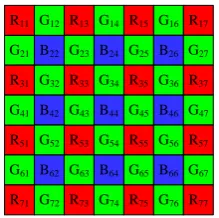
To simplify processes and reduce equipment costs, most digital devices usually exploit a single image sensor (e.g., CCD or CMOS) to capture the color image information. Due to that sensors can only detect the intensity of light and they are not sensitive to the differences of colors, a color filter must be installed in front of the sensor when capturing color images. In a single-sensor camera with color filter array (CFA), each pixel only receives one of the intensities among the three-color elements R, G, and B, and the other two pixels must be obtained by interpolation. The reconstruction process of the missing color planes is called demosaicking, which plays an important role in acquiring a full-color image. The most widely used mode is Bayer CFA array [1], shown in Figure 1. Half of the pixels in Bayer pattern are green pixels, because they are more useful for representing the image details and they are less affected by aliasing.
To enhance interpolation performance and image quality, many demosaicking algorithms have been proposed in the past literatures [2-5].
*Corresponding Author’s Email: [email protected] (C. Wang)
R13 G14 R15
G21 B22 G23 B24 G25
R31 R33 R35
R51 R53 R55
G32 G34
B42 B44
G41 G43 G45
G52 G54
R11 G12 G16 R17
B26 G27
G36 R37
B46 G47
G56 R57
G61
R71
B62
G72
G63
R73
B64
G74
G65
R75
B66
G76
G67
R77
Figure 1. Bayer CFA pattern with size of 7×7
To reduce the artifacts and overcome the above defects, another type of interpolation algorithms have been proposed and developed [6-20], which take advantage of the correlation among the three primary color channels. Under the criterion that edges have more luminance information (G) than chrominance information (R and B), Malvar et al. [6] designed several linear filters with size of 5×5 to calculate the missing values. For example, when estimating the green pixel at red location, this method remains red components near the green pixels. It corrects the bilinear method by adding a correction value. R and B pixels are estimated in a similar way. Moreover, the filter coefficients are determined by the Winner approach [7]. As expected, this method exploits many color components near the unknown pixel. Therefore, the reconstructed image has better visual quality. In addition, this method leads to 5.5 dB improvements in peak signal-to-noise ratio (PSNR) over the bilinear way. In literature [8], the linear filters with size of 5×5 are also used to interpolate the missing pixels. When generating the red values at green locations, the green pixels in four corners are discarded, which are different from the method in reference [6]. In literature [6], there are 9 nonzero coefficients for the G channel, and 11 for R and B estimation. However, in [8], 9 nonzero coefficients are used for the G channel and 7 nonzero coefficients are used for both R and B channels in image demosaicking. Therefore, the complexity is reduced. Meanwhile, the performance is reduced too. Wang et al. [9] proposed an improved method considering the fact that neighboring pixels contain more relevant information about the missing pixel. This method makes full use of the nearest neighboring pixels to interpolate R and B pixels at G locations. Better performance is obtained and it has the same computational complexity as [8]. Inspired by Luo et al.’s method [8] and Wang et al.’s method [9], we propose a trade-off image demosaicking method. The proposed method keeps lower computional complexity than [6] and obtains better performance than [8, 9] at the same time.
Some other demosaicking methods, which utilize the correlation among neighboring channels, have been proposed. In [10], Adams and Hamilton proposed a method based on horizontal and vertical gradient operators. Chrominance information and luminance information are applied in calculating the interpolation direction. Zhang et al. [11] proposed a new scheme to reconstruct the image. The missing components are first estimated by local directional interpolation, and then the non-local adaptive threshold is applied to enhance the local estimation. This method achieves better performance, but the complexity is increased as well. Chen et al. [12] presented a multidirectional weighted interpolation to estimate the missing components. However, the post-processing operation is required. Shi et al. [13] proposed an improved method by utilizing the
image edge information and the high execution speed of bilinear demosaicking. Specifically, they divided the mosaic area into two categories: edge region and smooth region. In smooth region, the missing pixels are interpolated by the bilinear method, which has low computational complexity and can be implemented in a real-time system. However, in edge area, the unknown pixels are generated with weighted values of multidirectional information, which brings high complexity problem. Since the edge property is more responsible for image visual quality, many improved algorithms based on edge information have been developed. In [14], edge property is analyzed firstly, and then the image is divided into three regions. Finally, the strong edge regions are interpolated. However, the superior performance is at the cost of high complexity. To reduce the false color values at the edges, Chen and Chang [15] proposed a framework, which determines different weights by an edge detection method. Song et al. [16] proposed an edge pattern based demosaicking algorithm. First, edge patterns are determined by nearest color values surrounding the unknown pixel, and then different adaptive steps are applied. This method can achieve low complexity, but the artifacts still exist.
These above algorithms are mainly about color differences, which can achieve good visual quality. To further improve the quality of reconstructed images, the residual-based interpolation methods for color image demosaicking have been developed in recent years. Kiku et al. [17] replaced the color differences with the residual interpolation based on the gradient based threshold free (GBTF) algorithm [18]. Experimental results show that the composite PSNR (CPSNR) of the algorithm is better than that of other methods based on color differences. In [19], they improved the former scheme by minimizing the Laplacian energy. The reconstructed image quality is improved. Based on the residual interpolation, Wang and Jeon [20] proposed a more effective algorithm for G channel interpolation. In the method, multidirectional weighted values are used to estimate the missing green values. As expected, the result is better. However, these methods need to determine the interpolation direction first, which brings high computational complexity, resulting in high costs in digital equipments. To solve the defects, we propose a linear interpolation method by taking advantage of correlation among the three primary channels. Compared with other methods in related literatures, the proposed algorithm has better performance and low complexity in the reconstruction of the full-color image.
2. BILINEAR INTERPOLATION AND LUO’s METHOD
Since the bilinear interpolation method estimates the missing values without considering the correlation among color channels, it has an extraordinary execution speed and it is a fundamental method of all these improved algorithms. As shown in Figure 1, Gij is the
green pixel in i row and j column, while Bij and Rij
are the blue and red pixels in the i row and j column, respectively. The missing color planes are estimated by averaging the known components, which are close to the missing pixels. It’s worth pointing out that pixels at boundaries are extended with mirror reflections of themselves.
For example, the green pixel value at red location is calculated by Equation (1):
23 43 32 34
33 ( ) / 4
G G G G G . (1)
A similar formula is applied when it is at blue location. The red values at green pixel location are interpolated as follows:
12 ( 11 13) / 2
R R R , (2)
23 ( 13 33) / 2
R R R , (3)
where, R12 is the red pixel in the red row and R23 is the red pixel in the red column. The following equation is used to estimate the red component at blue location.
22 ( 11 13 31 33) / 4
R R R R R , (4)
As for the blue pixel at red and green locations, it can be acquired in the same way. After these processes, a full-color image is reconstructed. However, it brings visible artifacts in edge regions, because it doesn’t give enough consideration to the correlation among the neighboring channels.
Luo et al.’s method [8] is based on the following fact: image edges have much more luminance information than chrominance information. Therefore, this method does not discard the red information when interpolating the green value at red location. Instead, they improve the bilinear interpolation method by adding a correction value. At the same time, its support region extends to a 5×5 pixel region, which is larger than that of bilinear interpolation. However, it brings high computational complexity. The filters designed in [8] are shown in Figure 2.
3. THE PROPOSED ALGORITHM
Based on the methods mentioned above, we propose an improved algorithm by using the primary colors’ correlation more effectively.
-1/8 -1/8
1/4
1/2
1/4
1/4 1/4 -1/8 -1/8
-1/8
1/4
1/2
1/4
-1/8
1/4 1/4 -1/8 -1/8
(a) (b)
5/8 1/2
1/2 -5/32
-5/32
-5/32 -5/32
5/8 1/2
1/2 -5/32
-5/32
-5/32 -5/32
(c) (d)
-3/16
1/4 1/4
3/4 -3/16 -3/16
1/4 1/4
-3/16
1/2 5/8
-5/32 -5/32
1/2
-5/32 -5/32
(e) (f)
5/8 1/2
1/2 -5/32
-5/32
-5/32 -5/32
-3/16
1/4 1/4
3/4 -3/16 -3/16
1/4 1/4
-3/16
(g) (h)
Figure 2. Linear filters used in [8]: (a) interpolating G at R
position; (b) interpolating G at B position; (c) interpolating R at G position in R row, B column; (d) interpolating R at G position in B row, R column; (e) interpolating R at B position; (f) interpolating B at G position in B row, R column; (g) interpolating B at G position in R row, B column; and (h) interpolating B at R position
Different from Luo et al.’s [8] method, we utilize the nearest green pixels when interpolating the red component at green location. Similarly, the blue component at green location is computed. The formula is as follows:
b R
( , ) ( , ) ( , )
g i j g i j i j , (5)
R
1
( , ) ( , ) ( , ) 4
i j r i j r i m j n
, (6)( , )m n {(0, 2), (0, 2), ( 2, 0), (2, 0)} . (7)
Thus, this method corrects bilinear interpolation by adding the difference values to control the correlation. When interpolating the green component at blue location, the formula is the same, but the bilinear interpolation is corrected by B( , )i j .
For interpolating R at blue location, we apply the formula:
b B
( , ) ( , ) ( , )
r i j r i j i j , (8)
where, B( , )i j is processed on a 5-point region. Similar formula is used to obtain B at red location.
We propose a new method for interpolating the R/B pixels at green location. Different from Luo et al.’s scheme, we reserve the nearest green pixels of the known red pixels and discard the pixels in four corners. Since these reserved pixels are closer to the unknown pixels, the correlation between reserved pixels and unkown pixels is at a high level and the demosaicking performance will be better.
The R component at green location can be calculated by:
b G
( , ) ( , ) ( , )
r i j r i j i j , (9)
where, G( , )i j is determined by a 7-point region, as shown in Figure 3.
Similarly, the B component is estimated as:
b G
( , ) ( , ) ( , )
b i j b i j i j , (10)
where, G( , )i j is computed on a 7-point filter region,
too.
To acquire the accurate values of the three primary colors, the gain factors ( ,
, and ) should be determined first. In [6], the three coefficients are computed by a Wiener approach. When
1/ 2,5 / 8
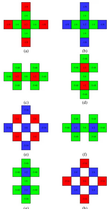
, and 3 / 4, the mean-square interpolation error would be the minimum. According to this, we design several linear filters whose support regions are 5×5, 3×5, or 5×3, respectively. There is no doubt that the more pixels the designed filters are used, the better interpolation performance of the proposed method will be. However, more pixels mean higher computational complexity. One way to evaluate the complexity is to count the number of nonzero filter coefficients within the designed filters. In [6], there are 9 nonzero coefficients for the G channel and 11 for both R and B channels. We achieve a lower complexity: 9 nonzero coefficients for the G channel and 9 for both R and B.
-1/8 -1/8
1/4
1/2
1/4
1/4 1/4 -1/8 -1/8
-1/8
1/4
1/2
1/4
-1/8
1/4 1/4 -1/8 -1/8
(a) (b)
5/8
1/2 1/2 -5/48
-5/48 -5/48
-5/48
-5/48 -5/48 1/2
5/8
1/2 -5/48 -5/48
-5/48 -5/48 -5/48
-5/48
(c) (d)
-3/16
1/4 1/4
3/4 -3/16 -3/16
1/4 1/4
-3/16
1/2 -5/48
-5/48
-5/48
5/8 1/2 -5/48
-5/48 -5/48
(e) (f)
5/8 1/2
1/2 -5/48
-5/48 -5/48
-5/48
-5/48 -5/48
-3/16
1/4 1/4
3/4 -3/16 -3/16
1/4 1/4
-3/16
(g) (h)
Figure 3. Linear filters used in this paper: (a) interpolating G
at R position; (b) interpolating G at B position; (c) interpolating R at G position in R row, B column; (d) interpolating R at G position in B row, R column; (e) interpolating R at B position; (f) interpolating B at G position in B row, R column; (g) interpolating B at G position in R row, B column; and (h) interpolating B at R position
4. EXPERIMENTAL RESULTS
To test the performance of the proposed algorithm, the Kodak test set [21] which contains 24 color images, as shown in Figure 4, is selected to test the interpolation effects. Throughout this paper, all experiments are conducted with MATLAB R2013a.
(a) (b) (c)
(d) (e) (f)
(g) (h) (i)
(j) (k) (l)
(m) (n) (o)
(p) (q) (r)
(s) (t) (u)
(v) (w) (x)
Figure 4. Kodak test images
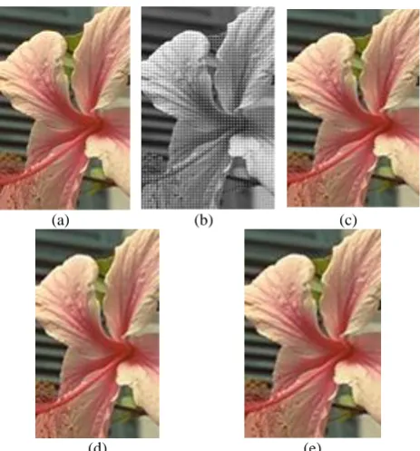
Compared with Luo et al.’s method, our proposed algorithm has about 0.5-1.0 dB improvement in R and B color channels and almost 1.0 dB improvement in CPSNR. Its CPSNR is also higher than that of Wang et al.’s. In addition to CPSNR, Figure 5 shows the interpolated performance of one image (Figure 4(g)) in the Kodak set from the view of visual effect.
TABLE 1. Comparisons of PSNR and CPSNR among Luo et al.’s method [8], Wang et al.’s method [9], and the proposed algorithm
Test Images
Luo et al.’s Method [8] Wang et al.’s Method [9] The Proposed Algorithm PSNR/dB CPSNR/
dB
PSNR/dB CPSNR/ dB
PSNR/dB CPSNR/ dB R G B R G B R G B
Figure 4(a) 28.81 35.54 28.74 30.10 29.44 35.54 29.55 30.75 30.55 35.54 30.33 31.58
Figure 4(b) 35.68 40.04 34.01 35.93 36.03 40.04 34.66 36.38 36.98 40.04 35.08 36.92
Figure 4(c) 36.80 42.32 35.29 37.26 37.25 42.32 36.31 37.95 38.24 42.32 36.57 38.45
Figure 4(d) 35.96 41.43 35.96 37.14 36.46 41.43 36.86 37.74 37.20 41.43 37.46 38.32
Figure 4(e) 30.45 36.68 29.81 31.43 31.40 36.68 31.00 32.38 32.40 36.68 31.46 33.00
Figure 4(f) 30.32 36.74 29.77 31.36 30.97 36.74 30.66 32.05 31.90 36.74 31.22 32.69
Figure 4(g) 36.22 41.83 35.08 36.88 37.27 41.83 36.28 37.88 38.41 41.83 36.77 38.54
Figure 4(h) 26.27 33.12 25.94 27.45 27.08 33.12 26.88 28.24 27.96 33.12 27.51 28.90
Figure 4(i) 34.82 41.41 34.53 36.00 35.61 41.41 35.62 36.84 36.64 41.41 36.37 37.61
Figure 4(j) 35.55 42.00 35.01 36.59 36.38 42.00 36.05 37.43 37.29 42.00 36.70 38.11
Figure 4(k) 32.27 37.94 31.81 33.27 32.87 37.94 32.62 33.89 33.78 37.94 33.21 34.53
Figure 4(l) 35.30 41.96 34.58 36.28 36.06 41.96 35.58 37.08 37.06 41.96 36.15 37.75
Figure 4(m) 27.67 32.68 27.14 28.56 28.13 32.68 27.68 28.99 28.85 32.68 28.17 29.50
Figure 4(n) 32.30 37.36 31.03 32.84 32.96 37.36 31.87 33.50 33.91 37.36 32.20 34.01
Figure 4(o) 33.84 39.40 32.99 34.64 34.62 39.40 33.83 35.35 35.44 39.40 34.24 35.87
Figure 4(p) 33.30 39.79 32.93 34.43 33.88 39.79 33.84 35.10 34.75 39.79 34.42 35.73
Figure 4(q) 35.24 40.47 34.83 36.21 36.04 40.47 35.63 36.90 36.75 40.47 36.23 37.45
Figure 4(r) 31.60 36.24 30.87 32.34 32.19 36.24 31.41 32.83 32.94 36.24 31.94 33.36
Figure 4(s) 30.68 37.23 30.35 31.83 31.42 37.23 31.14 32.52 32.38 37.23 31.99 33.31
Figure 4(t) 33.95 40.07 33.46 34.98 34.60 40.07 34.14 35.57 35.48 40.07 34.64 36.17
Figure 4(u) 31.54 37.45 30.98 32.52 32.27 37.45 31.86 33.24 33.15 37.45 32.42 33.85
Figure 4(v) 33.70 38.51 32.34 34.16 34.21 38.51 33.10 34.73 35.09 38.51 33.56 35.27
Figure 4(w) 37.73 43.06 36.63 38.38 38.32 43.06 37.45 39.01 39.34 43.06 37.92 39.62
(a) (b) (c)
(d) (e)
Figure 5. Experimental results: (a) original image, (b)
Bayer-patterned CFA image, (c) demosaicking by Luo et al.’s method, (d) demosaicking by Wang et al.’s method, and (e) demosaicking by the proposed algorithm
We can see that our proposed method outperforms other methods, especially at the petal edges, stigma, and style of the flower. The results are reasonable because we utilize more pixel information than bilinear interpolation. In addition, instead of using the four pixels in corners like Luo et al.’s method, we also reserve the nearest pixels to reconstruct the unknown pixel.
5. CONCLUSION
In this paper, we proposed an improved demosaicking method for Bayer-pattern CFA images. By using the correlation among RGB channels and reserving the nearest pixel values, this algorithm can maintain a relatively low complexity and achieve a better demosaicking performance objectively and subjectively. Due to its low complexity, it is easily implemented in digital devices. It should be noted that there are still color artifacts in these interpolated images. Thus, more work is needed for the accuracy of the interpolation and the quality of the reconstructed image.
6. ACKNOWLEDGEMENTS
This work was supported by the 12th student research training program (SRTP) and the 8th undergraduate
research apprentice program (URAP) at Shandong University (Weihai), China. Gang Yu and Ke Yu thank the computer vision and wireless communication (CVWC) research group at Shandong University (Weihai) for giving them the opportunity to do some research in their college years.
7. REFERENCES
1. Bayer, B.E., Color imaging array. (1976), Google Patents. 2. Menon, D. and Calvagno, G., "Color image demosaicking: An
overview", Signal Processing: Image Communication, Vol. 26, No. 8, (2011), 518-533.
3. Adams Jr, J.E., "Interactions between color plane interpolation and other image processing functions in electronic photography", in IS&T/SPIE's Symposium on Electronic Imaging: Science & Technology, International Society for Optics and Photonics., (1995), 144-151.
4. Longere, P., Zhang, X., Delahunt, P.B. and Brainard, D.H., "Perceptual assessment of demosaicing algorithm performance",
Proceedings of the IEEE, Vol. 90, No. 1, (2002), 123-132. 5. Yu, W., "Colour demosaicking method using adaptive cubic
convolution interpolation with sequential averaging", IEE Proceedings-Vision, Image and Signal Processing, Vol. 153, No. 5, (2006), 666-676.
6. Malvar, H.S., He, L.-w. and Cutler, R., "High-quality linear interpolation for demosaicing of bayer-patterned color images", in Acoustics, Speech, and Signal Processing, Proceedings.(ICASSP'04). IEEE International Conference on, IEEE. Vol. 3, (2004), 485-488.
7. Gunturk, B.K., Altunbasak, Y. and Mersereau, R.M., "Color plane interpolation using alternating projections", IEEE Transactions on Image Processing, Vol. 11, No. 9, (2002), 997-1013.
8. Luo, X., Sun, H., Chen, Q., Chen, J. and Wang, Y.-j., "Real-time demosaicing of bayer pattern images", Chinese J. Opt. Appl. Opt, Vol. 3, No. 2, (2010), 182-187.
9. Wang, D., Yu, G., Zhou, X. and Wang, C., "Image demosaicking for bayer-patterned CFA images using improved linear interpolation", in Information Science and Technology (ICIST), Seventh International Conference on, IEEE., (2017), 464-469.
10. Adams Jr, J.E. and Hamilton Jr, J.F., Adaptive color plane interpolation in single sensor color electronic camera. (1997), Google Patents.
11. Zhang, L., Wu, X., Buades, A. and Li, X., "Color demosaicking by local directional interpolation and nonlocal adaptive thresholding", Journal of Electronic Imaging, Vol. 20, No. 2, (2011), 023016.
12. Chen, X., He, L., Jeon, G. and Jeong, J., "Multidirectional weighted interpolation and refinement method for bayer pattern CFA demosaicking", IEEE Transactions on Circuits and Systems for Video Technology, Vol. 25, No. 8, (2015), 1271-1282.
13. Shi, J., Wang, C. and Zhang, S., "Region-adaptive demosaicking with weighted values ofmultidirectional information", Journal of Communications, Vol. 9, No. 12, (2014), 930-936.
15. Chen, W.-J. and Chang, P.-Y., "Effective demosaicking algorithm based on edge property for color filter arrays", Digital Signal Processing, Vol. 22, No. 1, (2012), 163-169.
16. Song, Z., Wang, D., Huang, Z. and Pang, Y., "Edge pattern based demosaicking algorithm of color filter array",
Transactions of Tianjin University, Vol. 19, No. 1, (2013), 29-36.
17. Kiku, D., Monno, Y., Tanaka, M. and Okutomi, M., "Residual interpolation for color image demosaicking", in Image Processing (ICIP), 20th IEEE International Conference on, IEEE., (2013), 2304-2308.
18. Pekkucuksen, I. and Altunbasak, Y., "Gradient based threshold free color filter array interpolation", in Image Processing (ICIP), 17th IEEE International Conference on, IEEE., (2010), 137-140.
19. Kiku, D., Monno, Y., Tanaka, M. and Okutomi, M., "Beyond color difference: Residual interpolation for color image demosaicking", IEEE Transactions on Image Processing, Vol. 25, No. 3, (2016), 1288-1300.
20. Wang, L. and Jeon, G., "Bayer pattern CFA demosaicking based on multi-directional weighted interpolation and guided filter",
IEEE Signal Processing Letters, Vol. 22, No. 11, (2015), 2083-2087.
21. Franzen, R., Kodak lossless true color image suite: PhotoCD PCD0992. (2002), Mar.
An Effective Image Demosaicking Algorithm with Correlation among
Red-green-blue Channels
X. Zhou, G. Yu, K. Yu, C. Wang
School of Mechanical, Electrical and Information Engineering, Shandong University, Weihai, China
P A P E R I N F O
Paper history:
Received 09 February 2017 Received in revised form 19 June 2017 Accepted 07 July 2017
Keywords:
Image Demosaicking Color Filter Array Bayer Pattern Color Correlation Gain Factors
ديكچ ه
متیروگلا کی ،هلاقم نیا رد
demosaicking
ریوصت یارب ،تسا یلصا گنر هس نیب هطبار ساسارب هک رثوم یریوصت
گنر رتلیف هیارآ اب کییازوم
Bayer (CFA)
تسا هدش داهنشیپ .
شهاک یارب
distortion
زاسزاب تیفیک دوبهب و ،ی
زا لماک هدافتسا ،هدش داهنشیپ یباینورد شور هبل تاعلاطا و ییانشور تاعلاطا
.دنک یم داجیا ار هناگدنچ یاهرتلیف ادتبا ام
داعبا اب 5 × 5 ، 3 × 5 و 5 × 3 م یحارط ار متیروگلا سپس و مینک ی
bilinear
.میهد یم دوبهب ار حلاصا رادقم اب هیبش
رد یزاس 24 رگید شور ود هب تبسن ام یداهنشیپ شور هک دهد یم ناشن کادک سکع رد
تبسن طسوتم زیون هب لانگیس
تیزوپماک
(CPSNR)
یرادید کاردا و .دراد یرترب
ط هب هک تسا نیا یداهنشیپ شور تیزم نیرتگرزب زا لماک رو
یاه لاناک نیب یگتسبمه
RGB
![Figure 2. Linear filters used in [8]: (a) interpolating G at R position; (b) interpolating G at B position; (c) interpolating R at G position in R row, B column; (d) interpolating R at G](https://thumb-us.123doks.com/thumbv2/123dok_us/206482.2014974/3.595.312.530.99.516/figure-interpolating-position-interpolating-position-interpolating-position-interpolating.webp)