Design and Implementation of Password
Based Security Lock System
M. Hymavathi 1, V. Srilatha2, C. Hemalatha 3, R. Swaroopa 4 , Faisal Khaled Awadh al Saleh5
Assistant Professor, Dept. of ECE, Lords Institute of Engineering and Technology, Hyderabad, Telangana, India1
UG Students, Dept. of ECE, Lords Institute of Engineering and Technology, Hyderabad, Telangana, India2,3,4,5
ABSTRACT:The main objective of this project is to provide a security system having the provision to change the password by the authority only. The security of any organization or house is of prime importance always. The concern is for the physical property and also for the intellectual property in case of any organization. This proposed system provides a user friendly security system for organizations and homes. This system is password based and allows only authorized person to access it with a password. It also has the provision of changing the password.The system is fully controlled by the 8 bit microcontroller of 8051 family. The password is stored in an EEPROM, interfaced to the microcontroller and the password can be changed any time unlike a fixed one burnt permanently on to the microcontroller. A keypad is used to enter the password and a relay to lock or unlock the electric door, which is indicated by a lamp. Any wrong attempt to open the door (by entering the wrong password) an alert will be actuated, indicated by another lamp.
KEYWORDS: Motor, Microcontroller, LCD, Keypad,Buzzer.
I. INTRODUCTION
Over the years, various control systems have beendesigned to prevent access to unauthorized user. Themain reason for providing locks for our buildings (home,office, church, school, etc) is for security of our lives andproperty. It is therefore important to have a stress free andconvenient means of achieving this purpose. Automaticdoors have become a standard feature on many differenttypes of buildings and they are becoming increasinglypopular every day with respect to developing an effectiveelectronic devices geared towards providing adequatesecurity. Home security has been a major issue ofconcern because of the dramatic increase in crime rateand everybody wants to take proper measure to preventintrusion or unwanted / unauthorized user. In addition,there was a need to automate home so that user can takeadvantage of the technological advancement in GSMtechnology and computer control system.
It is alsointeresting to know that commonly used devices like atelephone land line or the Global System of Mobilecommunication (GSM) can possess features which can beused domestically by individuals or industries to operateappliances like; door, electric bulb, television, refrigerator,air condition, robotic arm, etc. The microcontroller continuously monitors the keypad and if somebodyenters a password it will check the entered password with the password stored in the memory and if they match then themicrocontroller will switch on the corresponding device.The system will allow access to the person who knows the password and it will not allow access to unauthorized people.The system has an alarm to thwart the people who may try to break the protection barrier
II. RELATED WORK
captured by the photo diode whichis emitted by surrounding red LEDs and reflected by the finger.IR Laser sensors are
used to detect any obstacle. Sadeque RezaKhan et al. In [3] have presented Android based control systemto maintain the security of home main entrance and also the cardoor lock. System can also control the overall appliances in aroom. The mobile to security system or home automation systeminterface is established through Bluetooth. The hardware part isdesigned with the PIC microcontroller.
Lia Kamelia et al. In [4] have presented a part of smart hometechnology using Bluetooth in a mobile device. A system calleddoor locks automation system using Bluetooth-based AndroidSmartphone is proposed and prototyped. The hardware design fordoor-lock system is the combination of android smart phone asthe task master, Bluetooth module as command agent, Arduinomicrocontroller as controller center/ data processing center,and solenoid as door lock output. Raqibull Hasan et.al. In [5]have presented and analyzed the design and implementationof microcontroller based home security system using GSMtechnology. Two microcontrollers with other peripheraldevices which include Light Emitting Diode (LED), LiquidCrystal Display (LCD), Buzzer and Global System for MobileCommunication (GSM) Module are responsible for reliableoperation of the proposed security system.
III. SYSTEM ARCHITECTURE
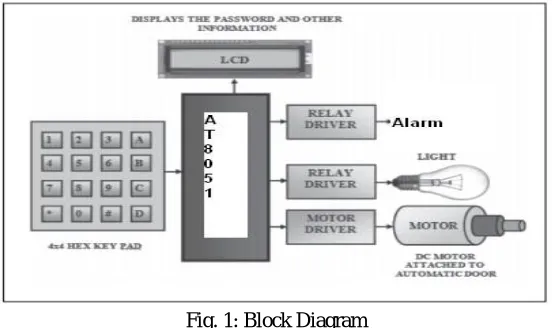
In this system the user will be prompted to set a password atinstallation. This password inputted at installation will continueto serve the lock until it is changed. User can change the currentpassword with a single key press. The program will check forcurrent password and allows the user to change password onlyif the current password is input correctly. If password is matchedwith pre-decided password then 8051 simply operates therelay to open the lights and alarm OFF. Also simultaneously operatea dc motor through motor driver for operating the door as shown in fig.1
Fig. 1: Block Diagram
Microcontroller: This is the CPU (centralprocessing unit) of our project. We are going to usea Microcontroller of 8051 family. The variousfunctions of microcontroller are like:
1) Reading the digital input from Keypad.
2) Sending this data to LCD so that the personoperating this project should read the password.
3) Sensing the password using keypad and to checkwhether it is a correct password or a wrong.Password and
rotate the stepper motor if thepassword entered is a correct password.
4) Sending the data to the computer using serialport. This data consist of the status of enteredPassword (Correct/wrong).
Fig. 2: LCD Pin Diagram
Liquid Crystal Display, which we are using in our project isJHD 1602A. This display consists of 16 columns and 2 rows.The library that is used is <liquidcrystal.h>.
Pin summary ofLCD 1602A
Pin 1: VSS.
Pin 2: To VDD 5V input.
Pin 3: VL to adjust LCD contrast with the help of 10Kpotentiometer. Low VL indicates light contrast and high VLindicates dark contrast.
Pin 4: RS for register select. Data registers used for high RS.Similarly, instruction register for low RS.
Pin 5: R/W signal stands for read/write. When R/W bit is high,it indicates a read operation. If R/W bit is low, it indicates writeoperation.
Pin 6: Clock Enable- Edge triggering. Pin 7 to 14: Represents from Bit 0 to Bit 7. Pin 15: back light Anode.
Pin 16: back light cathode.
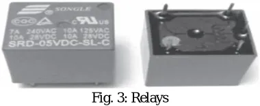
Relay: A relay is an electrical switch that opens and closesunder control of another electrical circuit. In the original form,the switch is operated by an electromagnet to open or close oneor many sets of contacts. These contacts can be either normallyopen (NO), normally closed (NC) or change-over contacts.Normally-open contacts connect the circuit when the relay isactivated. The circuit is disconnected when the relay is inactive.
Fig. 3 shows the relays.
Fig. 3: Relays
L293D Motor Driver IC: This device is a monolithic integratedhigh voltage, high current four channel driver designed to acceptstandard TTL logic levels and drive inductive loads (such asrelays solenoids, DC and stepping motors) and switching powertransistors. It uses two channels for driving two loads; each pairof channels is equipped with an enable input. Pin diagram ofL293D is shown in Fig. 4.
Buzzer: In our project the buzzer is used for beep sound eitherindicating the countdown time or wrong password. It is asshown below:
Fig. 5. Piezo Buzzer
IV. RESULTS & DISCUSSION
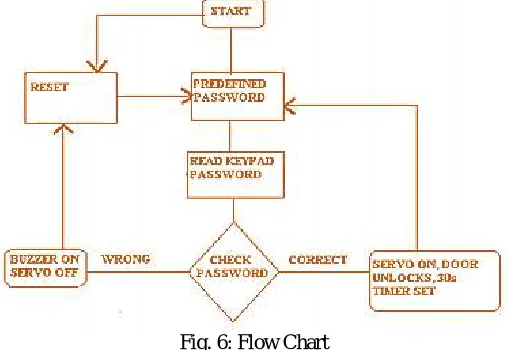
The flowchart as in fig.6 gives a brief idea as to how the project”Password Protected security Locking System using 8051” works.Initially the password is predefined. When the device isswitched on, it resets the motor angle to lock the door. Now theuser is prompted to enter the password. The user enters thepassword through a keypad which is read by the 8051. Nowthe entered password is checked with the predefined password.If the password matches, then the servo motor deflects and thedoor unlocks for 30s else the buzzer beeps indicating theinvalidity of the password.The step by step working is given as below. When the 8051 MCUis switched on, the LCD displays the entry screen message byinitializing and configuring the LCD pins to 8051.
Fig. 6: Flow Chart
Step 1:LiquidCrystal LCD (13, 12, 11, 10, 9, 8);Configure the LCD pins.
Next, the user is asked to prompt a password. Here the correctpassword is pre-initialized.
Step 2:char* pass=”A1B2C”; Initialize the correct password
Next, the password entered by the user is compared with thecorrect password. If the password entered by theuser matcheswith the correct password, then the following set of statementswill be executed.
Step 3:myservo.write(90); //The servo motor deflects to an angle of 90degrees enabling the user to unlock unlockdoor();// Unlocks the door for a specified amount of time
currpos=0;//reset the password enabling the user to enter anew password
myservo.write(0);//after the time exceeds the servo deflects theangle back to zero degrees. Else, the following set of statements will be executed
In the above case, the door will be unlocked by the movementof servo to a particular angle or remaining still depending uponthe user’s entered password.
Note: The entered password by the user is converted into‘*’ to provide strong privacy. For(l=0;l<=currpos;++l)
{
lcd.print (‘*’); }
Further, the buzzer is provided if the user enters a wrongpassword and also if the user exceeds the specified limit. Herewe have given the specified limit to be 20 secs.
Step 4:
if(i==21){
digitalWrite(19, HIGH); // buzzer beep lcd.setCursor(0,0);
V. CONCLUSION
This system is a goodsample of design and implementationof a low cost security system based 8051 microcontroller board. The paramount part of this project is that theuser can change the current password and lock the system againwith a key press. By using combination of 8051 Microcontroller and password protection one can make possiblesmart home automation effectively.Password protected locking/unlocking avoids unauthorized unlocking. Flexibility to theuser to change or reset the password makes it user friendly. Sothis system is cheap, reliable and effortlessly installable.
REFERENCES
1. Ajay Mudgiil, Shelja Dhawan, Swati Sharma, “Design anddevelopment of sensor based home automation and security systemusing GSM module and locking system”, International Journalof Advanced Engineering Research and Science (IJAERS), Vol-1,Issue-4, pp. 37-39, Sept. 2014.
2. Nikhil Agarwal, G.Subramanya Nayak, “Microcontroller basedHome Security System with Remote Monitoring”, InternationalConference on Electronic Design and Signal Processing (ICEDSP),pp. 38-41, 2012.
3. Sadeque Reza Khan, Farzana Sultana Dristy, “Android BasedSecurity and Home Automation System”, International Journalof Ambient Systems and Applications (IJASA), Vol. 3, No. 1, pp.15-24, March 2015.
4. Lia Kamelia, Alfn Noorhassan S.R, Mada Sanjaya , W.S., EdiMulyana, “Door-Automation System Using Bluetooth-BasedAndroid For Mobile Phone”, ARPN Journal of Engineering andApplied Sciences, Vol. 9, No. 10, pp. 1759-1762, October 2014.
5. Raqibull Hasan, Mohammad Monirujjaman Khan, AsaduzzamanAshek, Israt Jahan Rumpa, “Microcontroller Based Home SecuritySystem with GSM Technology”, Open Journal of Safety Scienceand Technology, 5, pp. 55-62, 2015.
6. Vijay P. Jadhao, “ARM based Smart Home Automation”,International Journal of Science and Engineering, Vol. 1, No. 2,pp. 53-56,2013. 7. Arpita Mishra, Siddharth Sharma, Sachin Dubey, S.K. Dubey,“Password Based Security Lock System”, International Journalof Advanced Technology in Engineering and Science, Vol., No. 2,Issue No. 05, pp. 100-103, May 2014.
8. Mohammad Amanullah, “Microcontroller Based ReprogrammableDigital Door Lock Security System by Using Keypad & GSM/CDMA Technology”, IOSR Journal of Electrical and ElectronicsEngineering (IOSR-JEEE), Vol. 4, Issue 6, pp. 38-42, Mar.-Apr.2013.
BIOGRAPHY
V. Srilatha presently pursuing B.Tech 3rd Year in Lords Institute of Engineering and Technology, Hyderabad, Telangana India.
C. Hemalatha presently pursuing B.Tech 3rd Year in Lords Institute of Engineering and Technology, Hyderabad, Telangana India.
R. Swaroopa presently pursuing B.Tech 3rd Year in Lords Institute of Engineering and Technology, Hyderabad, Telangana India.