Please cite this article as: E. Rahimi, M. H. Neshati,Development of an Enhanced Gain Substrate Integrated Waveguide H-plane Horn Antenna Using Thin Substarte, International Journal of Engineering (IJE), TRANSACTIONS B: Applications Vol. 29, No. 8, (August 2016) 1062-1067
International Journal of Engineering
J o u r n a l H o m e p a g e : w w w . i j e . i r
Development of an Enhanced Gain Substrate Integrated Waveguide H-plane Horn
Antenna Using Thin Substarte
E. Rahimi, M. H. Neshati*
Electrical Engineering Department, Ferdowsi University of Mashhad, Mashhad, Iran
P A P E R I N F O
Paper history: Received 09 July 2016
Received in revised form 14 July 2016 Accepted 14 July 2016
Keywords:
Horn Antenna
Substrate Integrated Waveguide (SIW) Antenna Measurement
A B S T R A C T
In this paper a dual band and high gain H-plane horn antenna implemented by substrate integrated waveguide (SIW) using a single layer thin substrate is introduced. The proposed antenna consists of five parts of rectangular waveguides with different widths arranged in a staircase manner to allow mode combination of fundamental and higher propagating modes of the structure. By adjusting the lengths and widths of different parts, suitable combination of amplitude and phase across radiating aperture is occurred and half power beamwidth at H-plane pattern is improved. A grounded pin is added at the middle of the radiating aperture to improve Side Lobe Level (SLL) and to obtain dual band operating condition. Moreover, by adding a metallic reflector plate around the radiating aperture, the antenna gain is enhanced. The proposed antenna has been successfully simulated, fabricated and its radiation performance including reflection coefficient, radiation patterns are measured in an anechoic chamber. Measured results show that antenna gain is 9.6 dBi and 7.2 dBi at the first and second band respectively.
doi: 10.5829/idosi.ije.2016.29.08b.05
1. INTRODUCTION1
The rapid development of wireless communication systems urge requirement for high performance antenna. Substrate Integrated Waveguide (SIW) technology is a very promising candidate for low cost and low loss antennas with suitable radiation performance. In addition, SIW has been widely attractive due to allowing fabrication of non-planar bulky rectangular waveguide using the planar printed circuit board (PCB) [1-7].
SIW based antennas, such as H-plane horns, [8] provide the merits of compact and easy integration compared to the conventional waveguides. However, these sectorial horn antennas offer a wide E-plane beamwidth, which is not suitable for point-to-point communication systems. In [9], a dielectric lens is added at the front of the radiating aperture of an H-plane SIW horn antenna using a single substrate and in turn antenna gain is improved up to 11.6 dBi. However, lens
1*Corresponding Author’s Email:[email protected] (Mohammad H.
Neshati)
corrected horns are only suitable for thick substrates,
6
h ,otherwise the effect of adding dielectric lens provides no advantages [10]. In [11] using a thick substrate of h=3.15 mm, dielectric loaded horn in conjunction with a patch at front of the radiating aperture is presented and low SLL with 10.5 dBi gain is obtained.
In this paper, a new dual band SIW horn antenna using a thin substrate of h=0.813 mm is introduced. The proposed antenna consists of five successive staircase rectangular parts with suitable width for exciting the fundamental and higher modes of the structure. By proper combination of these modes [10] and by suitable phase and amplitude, a nearly uniform electric field distribution along the aperture is obtained and in turn, the antenna directivity is highly improved.
2.ANTENNA DESIGN AND CONFIGURATION
structure consists of five rectangular parts with different widths. The first part is excited at the fundamental mode of TE10 by a 50 Ω coaxial probe using a SMA connector. For fabrication simplicity, the feed line is terminated by a planar capacitor with inner and outer radios of R1 and R2 respectively to obtain impedance matching. The proposed antenna is made using single layer of Rogers 4003 with electrical characteristics of εr = 3.55 and h=0.813 mm, which belongs to the category of thin substrates with h10 at 27.6 GHz. W2, W3 and W4 are chosen based on Equation (1) [12, 13] to excite TE10 mode of rectangular waveguide.
, 1, 2,3, 4,... 2
i r
W i
(1)
For the last part, W5 is chosen to excite both TE10 and TE30 modes. Also, its length, L5, is adjusted to obtain the same phase and appropriate amplitude for these modes at the radiating aperture. This led to nearly a uniform electric field distribution along the aperture [14] and in turn, lower beamwidth for H-plane pattern compared to that of the conventional horn is obtained.
However, using SIW technique, the amplitude of TE10 and other modes are not equal on the aperture and field distribution is not uniform. Therefore, a grounded pin using a via with diameter of 0.5 mm is added at the middle of the aperture to reduce SLL. Also, in order to increase antenna gain, a reflector plate is added around the aperture. The 3-dimensional view of the proposed antenna with the grounded pin and reflector is shown in Figure 2. The geometrical parameters of the proposed structure are summarized in Table I. The simulation process is performed by Ansoft HFSS software and a prototype of the antenna is made and tested in an anechoic chamber.
3. RESULTS AND DISCUSSION
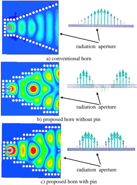
3. 1. Simulation Results The simulated electric field distribution inside the proposed horn and its aperture including the field distribution of the conventional horn is shown in Figure 3. It can be observed that field distribution of the proposed antenna without pin, as shown in Figure 3(b), is more uniform than that of the conventional horn. However, by adding the grounded pin at the middle of the aperture leads to suppressing negative portion of the field distribution on the aperture and as a result SLL at H-plane pattern is improved.
The simulated reflection coefficient for different horn antennas including the proposed SIW horn with the grounded pin and the reflector is shown in Figure 4. It can be seen that for the proposed antenna without pin, a weak resonance at 27.9 GHz is obtained. However, by adding the pin, the resonant frequency of the
conventional horn is slightly shifted and another resonant frequency at 27.8 GHz is well excited leading to dual band operation of the proposed structure.
3. 2. Parametric Study To study the effect of L5, the length of the final rectangular waveguide part of the structure, a parametric study is carried out.
TABLE 1. Geometrical parameters of the conventional and proposed SIW horns.
Parameter Value Parameter Value
W2 4.5 L2(proposed horn) 3
W3 6.5 L3 3
W4 8.5 L4 4
W5 10.5 L5 4.7
t 2.4 W 1
R 0.8 W1 5
R1 0.6 L1(conventional horn) 3
R2 1.1 L2(conventional horn) 14.9
A 15 θ 22.4°
L 2.1 a 5
L1(proposed horn) 3.3
All units are in mm, except for θ which is in degree.
A
L2
L1
a
L W
R1
R2
Probe
SIW horn
R
Figure 1. The SIW horn antennas, a) conventional horn, b) proposed SIW horn antenna.
Figure 2. The 3-dimentional view of the proposed structure with the grounded pin and reflector plate.
The variation of the antenna directivity versus L5 is shown in Figure 5. It can be seen that by increasing L5 up to 4.7 mm, the antenna directivity is increased. However, with further increasing of L5, the antenna directivity is decreased due to excitation of higher modes with inappropriate amplitude. Also, the effect of the reflector height on the radiation performance of the proposed SIW horn is studied. The results are shown in Figure 6, which shows that the minimum SLL for H-plane pattern with maximum directivity are obtained for the reflector height of t=2.4 mm.
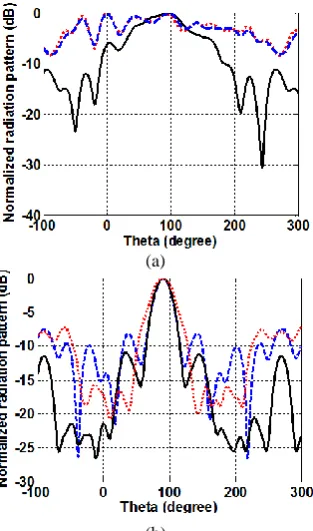
The simulated radiation patterns at the first band for both E- and H-plane of different horns are plotted in Figure 7. It can be seen that using the reflector plate SLL and backward radiation of E-plane pattern are significantly improved. For H-plane pattern, as shown in Figure 7(b), the new structure using five rectangular waveguides, the null beamwidth is improved compared to that of the conventional horn. It can also be concluded that using the grounded pin and the reflector plate, both SLL and FBR are highly improved.
3. 3. Measured Results A prototype of the proposed horn antenna is made by Rogers 4003 substrate with electrical characteristics of h=0.813 mm and r=3.55.
a) conventional horn
b) proposed horn without pin
c) proposed horn with pin
Figure 3. The simulated electrical field distribution inside and on the radiating aperture of different horns, a) conventional horn, b) proposed horn without pin, c) proposed horn with pin.
A photo of the fabricated proposed antenna and the measurement setup are illustrated in Figure 8. Measured results of S11 including simulated ones for the proposed horn are illustrated in Figure 9. It can be seen that a dual band operation at 27.9 GHz and 28.6 GHz is provided, while a good agreement is obtained between measured and simulated results.
Figure 4. The simulated results of S11 for different SIW horns versus frequency.
Figure 5. The simulated result of the proposed horn directivity versus L5.
Figure 6. The simulated results of the antenna directivity and SLL versus the reflector height.
0 1 2 3 4 5 6 7
1 2 3 4 5 6 7 8 9
L5 (mm)
D
(
d
B
)
0 0.5 1 1.5 2 2.5 3 3.5 4
8 8.5 9 9.5 10 10.5
t (mm)
D
(
d
B
)
0 0.5 1 1.5 2 2.5 3 3.5 4-10.5
-10 -9.5 -9 -8.5 -8
S
L
L
(
d
B
)
radiation aperture
radiation aperture
(a)
(b)
Figure 7. The simulated radiation patterns of different horns a) E-plane at first band, b) H-plane at first band.
The measured patterns at two bands are plotted in Figure 10 including the simulated ones. It can be seen that the measured radiation patterns are in good agreement with those obtained by simulation.
Figure 8. The Photo of the fabricated antenna and the experimental setup for antenna measurement.
Figure 9. The measured and simulated results of S11 of the proposed SIW horn with the grounded pin and reflector.
(a)
(b)
(c)
(d)
Figure 10. The measured and simulated patterns, a) E-plane at first band, b) H-plane at first band, c) E-plane at second band, d) H-plane at second band
26 26.5 27 27.5 28 28.5 29
-35 -30 -25 -20 -15 -10 -5 0 Freq (GHz) S 11 Measure simulation
-50 0 50 100 150 200 250
-40 -30 -20 -10 0 Theta (degree) N o rm a li ze d r e d ia ti o n p a tt e rn ( d B ) Measure Simulation
-50 0 50 100 150 200 250
-40 -30 -20 -10 0 Theta (degree) N o rm a li ze d r a d it io n p a tt e rn ( d B ) Measure Simulation
-50 0 50 100 150 200 250
-40 -30 -20 -10 0 Theta (degree) N o rm a li e d r a d ia ti o n p a tt e rn ( d B ) Measure Simulation
-50 0 50 100 150 200 250
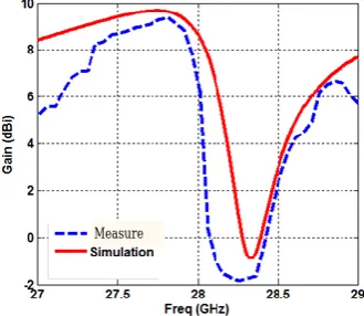
Moreover, for the second band, H-plane pattern is nearly flat around 90. It is believed that due to increasing electrical length of L5, the amplitude of higher modes at the aperture is higher than the amplitude of the fundamental mode at the second band, and so a flat pattern is performed. Variation of the measured gain versus frequency including the simulation result are plotted in Figure 11. It can be seen that variations of both are nearly the same with peak measured gain of 9.6 dBi at 27.9 GHz. In case of the second band at 28.6 GHz, the measured gain is 7.2 dBi.
Figure 11 shows that at 28.3 GHz, between the two operating bands, the antenna gain is dropped to -1.5 dBi and after that, the antenna gain is montonically increased up to the second band. This is due to increasing electrical length of L5, and hence the amplitude of higher modes on the radiating aperture is higher than the required value, which result in a null at
90
for H-plane pattern.
The detailed radiation performance of all SIW horn antennas are summarized in Table 2.
It is worthwhile to consider that for a conventional horn with reflector plate, the antenna gain is improved from 5.3 dBi to 7.9 dBi, while for the proposed horn with pin and reflector, the antenna gain is reached to 9.6 dBi at the first band.
Figure 11. The measured and simulated antenna gain of the propsed antenna versus frequency.
TABLE 2. The detailed radiation performance of the conventional and proposed horns.
Conventional horn Proposed Horn
parameter reflector without reflector with reflector & pinwithout
with reflector & pin
simulation measured
first band
second band
first band
second band
Gain (dBi) 5.3 7.92 7 9.8 7.5 9.6 7.2 Front to Back Ratio (dB) 7.7 11.6 7.4 15 10 17.5 12 Impedance bandwidth (MHz) 190 220 180 180 200 180 210 Efficiency (%) 73 82 65 80 80 --- --- Antenna size (mm2) 18.317.3 18.318.3 18.817.3 18.318.3 18.318.3 18.318.3 18.318.3
SLL (dB) -16.3 -23.2 -7.7 -10.5 -24 -9.6 -23 CPL (dB) -20 -21 -18 -20 -19 -21 -20
4. CONCLUSION
In this paper, a new dual band SIW H-plane horn antenna structure using five parts of rectangular waveguide with different widths placed in a staircase manner is introduced. By combining TE10 and higher propagating modes of the structure, proper field distribution along the radiation aperture of the proposed SIW horn is obtained and in turn, HPBW of H-plane pattern is highly improved. By adding a grounded pin at the centre of the radiating aperture and a metallic reflector plate around it, both SLL and the antenna directivity is enhanced. A prototype of the proposed antenna is made using a single layer of substrate. The fabricated antenna is successfully tested in anechoic chamber and measured results agree well with those obtained by simulations. It is shown that at first band of 27.9 GHz the antenna gain is 9.6 dBi. The proposed antenna also provides at least 7.2 dBi gain at 28.6 GHz with a nearly flat H-plane pattern.
5. ACKNOWLEDGMENT
The authors would like to thank the atenna type aproval labratory of the University of Tehran for experimental precedure of the proposed antenna.
6. REFERENCES
1. Liu, B., Hong, W., Kuai, Z., Yin, X., Luo, G., Chen, J., Tang, H. and Wu, K., "Substrate integrated waveguide (siw) monopulse slot antenna array", IEEE Transactions on Antennas and Propagation, Vol. 57, No. 1, (2009), 275-279.
2. Dong, Y.D. and Itoh, T., "Composite right/left-handed substrate integrated waveguide leaky-wave antennas", in Microwave Conference, 2009. EuMC 2009. European, IEEE. Vol., No. Issue, (2009), 276-279.
3. Rahimi, E. and Neshati, M.H., " Low Profile Modified H-Plane SIW Horn Antenna with Improved Directivity", 3rd Conference
on Millimeter Wave & Terahertz Technologies, Tehran, (2015), 35-37.
4. Che, W., Fu, B., Yao, P., Chow, Y. and Yung, E.K., "A compact substrate integrated waveguide h‐plane horn antenna with dielectric arc lens", International Journal of RF and Microwave Computer‐Aided Engineering, Vol. 17, No. 5, (2007), 473-479.
5. Dashti, H. and Neshati, M., "Comparative investigation of half-mode siw cavity and microstrip hybrid antenna using different patch shapes", International Journal of Engineering-Transactions A: Basics, Vol. 27, No. 10, (2014), 1573-1580. 6. Dashti, H. and Neshati, M., "Design investigation of microstrip
patch and half-mode substrate integrated waveguide cavity hybrid antenna arrays", International Journal of Engineering-Transactions B: Applications, Vol. 28, No. 5, (2015), 686-692. 7. Neshati, M.H. and Wu, Z., "Probe-fed rectangular dielectric
resonator antennas: Theoretical modeling and experiments",
International Journal of Engineering, Vol. 16, No. 1, (2003), 41-46.
8. Neshati, M.H. and Razavi Parizi, S.A., "Low profile h-plane horn antenna based on half mode substrate integrated waveguide (hmsiw) technique", in 20th Iranian Conference on Electrical Engineering, (2012).
9. Wang, H., Fang, D.-G., Zhang, B. and Che, W.-Q., "Dielectric
loaded substrate integrated waveguide (siw)-plane horn antennas", IEEE Transactions on Antennas and Propagation, Vol. 58, No. 3, (2010), 640-647.
10. Esquius-Morote, M., Fuchs, B., Zürcher, J.-F. and Mosig, J.R., "Novel thin and compact h-plane siw horn antenna", IEEE Transactions on Antennas and Propagation, Vol. 61, No. 6, (2013), 2911-2920.
11. Gong, L., Yuk-Chan, K. and Ramer, R., “Substrate Integrated Waveguide H-plane Horn Antenna with Improved Front-To-Back Ratio and Reduced Side Lobe Level,” accpeted for publication in IEEE, Antenna and Wireless Propag. letters, DOI 10.1109/LAWP.2016.2538823, August. 2015.
12. Balanis, C.A., Advanced Engineering Electromagnetics. 1989,
ed: John Wiley & Sons, USA, 1989
13. Kraus, J.D., Antennas, second edition, McGra Hill International Company, USA, 1988
14. Wang, L., Yin, X., Li, S., Zhao, H., Liu, L. and Zhang, M., "Phase corrected substrate integrated waveguide h-plane horn antenna with embedded metal-via arrays", IEEE Transactions on Antennas and Propagation, Vol. 62, No. 4, (2014), 1854-1861.
Development of an Enhanced Gain Substrate Integrated Waveguide H-plane Horn
Antenna Using Thin Substarte
E. Rahimi, M.H. Neshati
Electrical Engineering Department, Ferdowsi University of Mashhad, Mashhad, Iran
P A P E R I N F O
Paper history: Received 09 July 2016
Received in revised form 14 July 2016 Accepted 14 July 2016
Keywords:
Horn Antenna
Substrate Integrated Waveguide (SIW) Antenna Measurement
ديكچ ه
ِحفص یرَپیش يتًآ ِلاقه يیارد
H
ِئارا ُذش ِتخاس کزاً ِیلا ریز کی زا ِک لاات ُرْت ات ُذًات ٍد ِیلا ریز ات ُذش عوتجه
یه ضرع ات یلیطتسه رثجَه توسق جٌپ لهاش یداٌْشیپ يتًآ .دَش ِت ِک تسا تٍافته یاّ
ِلپ ترَص ِت یا رارق نّ لاثًد
ِتفرگ باختًا ات .ذًَش یه کیرحت ىآ رتلاات ِثتره ٍ ةلاغ یاّذه ٍ ذًا شخت زا کی رّ ضرع ٍ لَط ةساٌه
،یرثجَه یاّ
یه ٍ ٌِهاد زا یثساٌه ةیکرت ِت ىاَت ِحفص ىاَت نیً َترپ یاٌْپ ِک ذیسر رتلاات ِثتره یاّذهٍ لٍا ِثتره ذه زاف
H
.ذتای شّاک
ّد سکره رد )يیپ( کچَک یسلف ًِاَتسا کی زا ةیترت ِت ُرْت رثَه دَثْت ٍ یعرف یاّ گرثلگ حطس شّاک یارت یعشعشت ًِا
یه ُدافتسا یعشعشت ًِاّد فارطا ُذٌٌک سکعٌه ِحفص ٍ یارت ٍ ُذش یزاس ِیثش راسفا مرً زا ُدافتسا ات یداٌْشیپ يتًآ .دَش
ُزاذًا جیاتً ،ىآ زا ُذش ِتخاس ًَِوً کی ُزاذًا جیاتً .تسا ُذش ِئارا عشعشت یَگلا ٍ ُرْت ،باتزات ةیرض لهاش یریگ
ات یریگ
ش زا لصاح جیاتً ِیث
ُزاذًا جیاتً .ذًراد رگیذکی ات یتَخ قتاطت یزاس ریداقه ُرْت یارت یریگ
dBi
6
/
9 ٍ
dBi
2
/
7 ِت رد ةیترت
.تسا مٍد ٍ لٍا ذًات