Geometrical Methods of Nonlinear Dynamics
in Ship Capsize
Jesse d'Assunçâo Rebelle de Souza, Junior
Thesis submitted for the degree o f
Doctor o f Philosophy
Centre for Nonlinear Dynamics and Its Applications
U
n i v e r s i t yC
o l l e g eL
o n d o nProQuest Number: 10042812
All rights reserved
INFORMATION TO ALL USERS
The quality of this reproduction is dependent upon the quality of the copy submitted.
In the unlikely event that the author did not send a complete manuscript and there are missing pages, these will be noted. Also, if material had to be removed,
a note will indicate the deletion.
uest.
ProQuest 10042812
Published by ProQuest LLC(2016). Copyright of the Dissertation is held by the Author.
All rights reserved.
This work is protected against unauthorized copying under Title 17, United States Code. Microform Edition © ProQuest LLC.
ProQuest LLC
789 East Eisenhower Parkway P.O. Box 1346
ABSTRACT
After centuries of designing and building ships, understanding the dynamic
behaviour of marine vessels in severe seas is a difficult problem that still
challenges naval architects. Capsize in rough weather does occur regularly,
perhaps because of this lack of understanding of dynamic stability. The many
accomplishments in the field o f mathematical modelling o f large-amplitude ship
motions still have to be matched by corresponding achievements in the
understanding o f the dynamics of those models.
We investigate in this work the essential features of current ship stability criteria,
as well as the mathematical modelling o f large-amplitude ship motions. Here we
develop our own model of coupled heave-roll motions, in which both direct and
internal parametric resonances are present. We then review the most relevant
aspects o f geometrical nonlinear dynamics with emphasis on some o f the
concepts and methods used to investigate the complex nonlinear phenomena
related to ship capsize: attractor-following techniques, and bifurcation diagrams,
transient and steady-state basin erosion phenomena, and integrity diagrams.
Finally, we show how this approach, based on theoretical and numerical studies,
can lead to a simple yet robust method to evaluate the dynamic stability o f ships.
Here we base our results on key observations about the nature and features of
the processes o f erosion and loss of transient safe basins. Through the use of
coarse grids o f starting conditions the method allows the construction of
boundaries of safe motion in the space o f phase variables and parameters. The
predictions o f this method can be easily checked against the results o f low-cost
experiments with physical models.
With this work we hope to have contributed to the ongoing efforts to understand
the complex nonlinear phenomena governing large-amplitude ship motions and
capsize, and to have showed that such knowledge can be applied in the
ACKNOWLEDGEMENTS
I would like to thank the members of the Centre for Nonlinear Dynamics
for providing a stimulating research atmosphere, and in particular to Dr Paul
Holborn for his friendship during these last four years. Dr Steven Bishop has
made significant contributions to this work, and I want to thank him for his help
and guidance.
I am indebted to my supervisor Professor Michael Thompson for his help with
this work and, more importantly, for his example o f positive attitude towards
serious research in engineering.
I also want to thank my colleagues at the Department o f Naval Architecture and
Ocean Engineering of the University of Sao Paulo for their support o f my project
of developing my doctoral studies in England.
This research programme was financed by the University o f Sao Paulo (Brasil),
the Brazilian Navy, and the Fundaçâo de Amparo à Pesquisa do Estado de Sao
Paulo (FAPESP) to all o f which I express my gratitude.
Finally, I want to thank my wife Denise who has now been for fourteen years a
permanent source o f love and inspiration for me, and is at this very moment
Table o f Contents 4
T A B L E O F C O N T E N T S
A b s tr a c t... 2
A ck n o w led g em en ts... 3
Table of C o n te n ts... 4
L ist o f F ig u r e s ... 7
L ist o f T a b le s ...10
1 IN T R O D U C T IO N 1.1 Scope of this w o rk ... 11
1.2 Objectives of this w ork...17
1.3 Overview of the contents... 18
2 CU R R EN T SH IP ST A BILITY CRITERIA 2.1 The need for better stability criteria: historical background...20
2.2 The GZ-Curve criterion: description...24
2.3 The GZ-Curve criterion: general comments... 27
2.4 Brief survey of works on ship stability criteria... 31
3 M A TH EM A TIC A L M OD ELLING OF SHIP M O TIO N 3.1 Objective o f mathematical modelling... 35
3.2 Basic ship capsize mechanisms in waves... 36
3.2.1 Pure loss o f stability in waves...37
3.2.2 Low-cycle (or parametric) resonance...38
3.2.3 B roaching... 38
3.2.4 Capsize in beam seas... 39
3.3 On the prediction o f ship motions...40
3.4 Basic formulation o f the problem of ship m otions... 41
3.5 The rôle of simplified mathematical m odels... 43
Table o f Contents 5
3.6.1 Preliminaries...43
3.6.2 The escape equation...45
3.7 Two-degrees-of-freedom (2-DOF) models... 48
3.7.1 An archetypal 2-DOF model of ship motions... 49
3.7.2 Equations o f motion in non-dimensional fo rm ...55
3.7.3 Underlying potential system ...56
4 G EOM ETRICAL A PPR O A C H TO NO N LIN EA R D Y N AM IC S 4.1 Brief historical background...60
4.2 Preliminaries... 62
4.3 Long-term dynamical behaviour: steady-state co n cep ts... 63
4.3.1 A simple model of ship rolling... 66
4.3.2 Underlying potential system ...69
4.3.3 Damped, unforced system ... 73
4.3.4 Periodically forced system... 76
4.4 Elements of bifurcation th e o ry ... 79
4.4.1 Bifurcations of periodic o rb its... 80
4.4.2 Global bifurcations: tangling of invariant manifolds... 84
5 DY NAM IC S OF SH IP M OTIONS LEADING TO C A PSIZE 5.1 Preliminaries: numerical methods in dynamics... 87
5.2 Overview o f steady-state response... 89
5.2.1 Quasi-steady-state response in time series p lo ts...89
5.2.2 Steady-state response: Poincaré sections... 92
5.3 Bifurcation diagram s...96
5.3.1 Attractor-following technique... 96
5.3.2 Bifurcations of the main sequence for the SIR model... 98
5.4 Basins of attractio n ... 106
5.4.1 Grids of sta rts...106
5.4.2 Sample of basins of attraction for the SIR model... 107
Table o f Contents 6
5.5.1 Transient versus steady-state dynamics...111
5.5.2 Transient dynamics: preliminaries... 112
5.5.3 Overview of transient escape in the SIR m odel... 118
5.5.4 Safe basins through grids-of-starts...122
5.6 Safe basins in control-parameter space for the SIR model...126
5.7 Evolution of safe basins...133
5.7.1 Loss of safe basin near resonance... 133
5.7.2 Processes of loss of safe basin... 138
5.7.3 Integrity diagram s... 147
6 THE M ETH O D OF A COARSE G R ID -O F-STA R TS 6.1 Preliminaries... 152
6.2 Dynamics in potential wells...153
6.2.1 One degree-of-freedom systems...154
6.2.2 Two-degrees-of-freedom system s... 161
6.3 Heuristics and description of the... method...163
6.4 Sensitivity study... 168
6.4.1 Selection of dynamical systems...168
6.4.2 Results o f sensitivity study... 172
6.4.3 Comparison with the literature... 177
6.5 Boundaries of safe motion for the SIR m odel...182
7 C O N C L U S IO N S ...188
A P P E N D IX A: PO TEN TIA L ENERGY FU N C TIO N S 194 A. 1 Introduction... 194
A.2 Expressions for potential energy... 197
A.3 Results for homogeneous body of square cross-section...199
A.4 The SIR model assumption...202
List o f Figures 1
LIST OF FIGURES
2.1 - Hydrostatic forces acting upon a heeled ship...25
2.2 - The IMO Weather Criterion... 26
3.1 - Motion of a particle in a potential w e ll... 47
3.2 - Restoring and potential functions for the escape equation...48
3.3 - Geometrical parameters for coupled heave-roll motion... 50
3.4 - Potential well for heave-roll m odel... 57
4.1 - Typical restoring moment function for a vessel... 67
4.2 - (a) Potential energy function for equation (4.13) (b) Outline of trajectories of (4.13) in phase sp ace...71
4.3 - Phase portrait for system (4 .1 4 )... 75
5.1 - Escape under slowly increasing amplitude of forcing... 91
5.2 - Selection of attractors in the main sequence; Poincaré p o in ts...93
5.3 - Selection of attractors in the main sequence: trajecto ries... 95
5.4 - Bifurcation diagrams for SIR equations... 99
5.5 - Bifurcation diagrams for SIR equations - detail of region A A '...101
5.6 - Bifurcation diagrams for SIR equations - detail of region BB'... 102
5.7 - Bifurcation diagrams for the SIR equations with i^=1.4...104
5.8 - Sketch of bifurcation curves for the SIR equations... 105
5.9 - Basin of attraction of the origin for the unforced SIR equ atio n s... 108
5.10 - Basins of attraction for the forced SIR equations... 109
5.11 - SIR model: values o f F required for escape within 8 cy cles... 119
5.12 - Contours of constant F-values required for escape... 120
5.13 - Individual curves of minimum F required for escape...121
5.14 - SIR model: safe basins in the control-parameter spaces... 129
5.15 - 1-DOF approximation to SIR model: safe basins... 131
L ist o f Figures 8
5.17 - Evolution of safe basins for the SIR equations with <y = 0 .8 5 ...135
5 .1 8 - Evolution of safe basins for the roll model (4.11) with co = 0.85... 136
5.19 - Evolution of safe basins for the escape equation with <y = 0.85...137
5.20 - Evolution of safe basins for the escape equation with = 0.55...142
5.21 - Evolution of safe basins for the roll model (4.11) with 6? = 0.55... 143
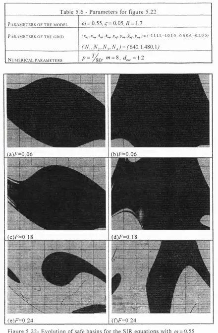
5.22 - Evolution of safe basins for the SIR equations with ûj = 0 .5 5 ... 144
5.23 - Integrity diagrams for the escape equation (3 .8 )...149
5.24 - Integrity diagrams for the SIR equations with varying R... 150
5.25 - Integrity diagram for the SIR equations at 7? = 1.7... 151
6.1 - Orbits around a centre... 157
6.2 - Orbits around a sink... 158
6.3 - Particle in a two-dimensional potential w e ll... 162
6.4 - Example o f a two-dimensional grid-of-starts... 167
6.5 - Potential well for equation (6.13)... 170
6.6 - Potential well for equation (6.14)...170
6.7 - Potential well for equation (6.15)... 171
6.8 - Potential well for equation (6.16)... 171
6.9 - Potential well for equation (6.17)... 172
6.10 - Sensitivity study: equation (6 .1 3 )...173
6.11 - Sensitivity study: equation (6 .1 4 )...174
6.12 - Sensitivity study: equation (6 .1 5 )...174
6.13 - Sensitivity study: equation (6 .1 6 )...175
6.14 - Sensitivity study: equation (6.17), one-dimensional g rid s... 175
6.15 - Sensitivity study: equation (6.17), two-dimensional g rid s... 176
6.16 - Boundaries o f safe motion: equation (6.13)... 179
6.17 - Boundaries of safe motion: equation (6 .1 4 )... 179
6.18 - Boundaries of safe motion: equation (6 .1 5 )... 180
6.19 - Boundaries of safe motion: equation (6 .1 6 )... 180
6.20 - Boundaries of safe motion: equation (6.17)... 181
6.21 - One- and two-dimensional grids for the SIR m odel...183
List o f Figures 9
6.23 - Boundaries of safe motion for the SIR model;
influence of grid size... 185
6.24 - Boundaries of safe motion for the SIR model: effect of grid density... 187
A. I - Main dimensions of body of rectangular cross-section...195
A.2 - Basic coordinates for the floating square cross-section body... 196
A 3 - Relative positions between body and w ater... 196
A.4 - Contours o f constant potential energy... 201
List o f Tables 10
LIST OF TABLES
5. 1- Parameters for figure 5 .1 7 ... 135
5.2 - Parameters for figure 5 .1 8 ... 136
5.3 - Parameters for figure 5 .1 9 ... 137
5.4 - Parameters for figure 5 .2 0 ... 142
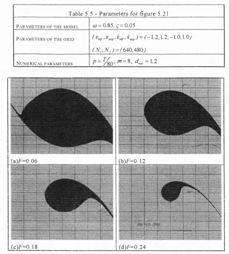
5.5 - Parameters for figure 5 .2 1 ... 143
5.6 - Parameters for figure 5 .2 2 ... 144
5.7 - Parameters for figure 5 .2 3 ... 148
5.8 - Parameters for figure 5 .2 4 ... 150
5.9 - Parameters for figure 5 .2 5 ... 151
6.1 - Main features o f selected systems... 177
Chapter One: Introduction 11
1. IN TR O D U C T IO N
1 .1 Sc o p e o f t h i s w o r k
This work is an application of the conceptual framework, and methods of
nonlinear dynamics to the problem of ship capsize. Both subjects - ship dynamics
and nonlinear dynamics - are today vast disciplines. No attempt can therefore be
made here to provide a complete account of any of those areas. Far from that,
we shall be just selecting a few tools available from the already considerable
repertoire of nonlinear dynamics. As to ship dynamics, we shall try to define a
problem in such a way that the resulting set o f equations is at the same time
amenable to analysis and significant from a practical point o f view.
In any work o f this kind many arbitrary choices are made, their number perhaps
too large to allow comprehensive listing. The fact that they are arbitrary means
that a different set of choices could equally be made, resulting in a different
work. The only hope one may have is that the particular set of choices one
makes proves itself useful.
Since we are concerned here with ship capsize, it is probably useful to start by
explaining the general meaning of this phrase in the context o f this work. We
shall be referring to ships, boats, and vessels as synonyms throughout this work,
without any particular sense of size necessarily attached to any o f these terms. In
general they will be referring to ship-like, sea-going vessels. Sometimes,
statements may apply to a wider category of vessels, including offshore
platforms, in which case we shall try to indicate it clearly.
From a naval architecture point of view, capsize can be defined in a few different
ways. They all have in common that after capsizing the vessel is unable to
recover its normal floating position without external aid. In this work we are
Chapter One: Introduction 12
often of acceptable oscillations around it) due to excessive roll motion - although
the effect of other motions, particularly heave, will be considered.
Before going into a more detailed discussion of ship capsize and nonlinear
dynamics, we would like to put the first of these two subjects into a broad
perspective. This might help us understanding how the modern approaches o f
systems dynamics can contribute to real improvements in the knowledge o f the
complex physics involved.
Capsize in severe weather is a long standing problem in Naval Architecture. Like
many other extreme responses of engineering systems, capsizing is not a common
event. Most vessels would not be expected to capsize during their operational
lives, either intact or in a damaged condition. Small vessels, like fishing boats
are, however, more at risk o f intact capsizing. National Research Council (1991).
The number o f capsizes still observed today is large enough to make professional
fishing at open sea the most dangerous occupation in the U.S.A., Jons et al
(1987). Capsizing o f vessels usually represents large material losses, the risk of
human lives, and depending on the nature o f the cargo, considerable
environmental damage.
For many centuries, sea-going vessels were designed and built solely based on
experience. In fact, successful use of sea-going vessels preceded any formal
knowledge o f the underlying physics by thousands of years. In today's language
we may say that this relative success was due not only to the ingenuity of ancient
naval architects, but also to the relative lack of difficulty in building a stable
vessel. Trial-and-error allowed reasonably safe vessels to be built, stimulating
further developments in the field. At first thought, it is therefore somewhat
surprising that after so many years of experience and with all the present
knowledge of physics ships still capsize regularly.
Why can ships capsize at all? Why are they not built in such a way that capsizing,
or at least intact capsizing, is just impossible? Clearly the answer lies on the fact
Chapter One: Introduction 13
some o f which conflict with ship stability. The vertical position of the centre of
gravity is a typical case. A vessel can be built with such a low centre of gravity
that the only stable floating position is upright. No matter how large the
disturbance such vessel always returns to its original position. Unfortunately,
however, such flexibility in positioning the centre of gravity o f a vessel is not
available when designing most merchant, naval or work vessels. The final
position o f the centre of gravity is the result of a large number of factors
involved in the vessel's layout. As a consequence, for every one o f those vessels
there are indeed other stable floating positions apart from the desirable, upright
one. The vessel is drawn towards them, and therefore towards capsize, by
unacceptably large amplitude motions. This suggests that we turn our attention
to the production o f large amplitude motions, particularly roll motion.
There is a fundamental reason for the propensity o f ships to display large
amplitude roll motions. One main purpose of a vessel being to move forwards
with minimum effort, the natural geometry is one in which the vessel's cross-
section area transverse to the direction of motion is kept small. This will reduce
hydrodynamic drag, especially if the shape of the vessel's bow is streamlined.
Now, to maximise the displacement of the vessel (and consequently the amount
of cargo it can carry) its length is increased. The resulting shape is that of a
slender body. In the past, the slenderness of the vessel used to be limited by
structural factors; amidships sections would have to be too heavy to withstand
the mechanical loads imposed by a long body. More recently, the use of high
tensile strength materials, particularly steel, has made common the construction
of ships whose length can be more than ten times larger than their breadth or
depth. As a consequence, typical sea-going vessels offer relatively small
resistance to motions around their longitudinal axis - rolling motion - and
therefore are likely to respond with large-amplitude roll motions to excitation in
that direction.
The characteristic behaviour o f ships as summarised above is obviously worsened
by the presence of sea waves and other environmental agents. For instance, as an
Chapter One: Introduction 14
transverse waves. Considerable disturbances can be expected in such situations,
even more so in severe weather. In fact, if large beam waves act upon ships, their
pilots will normally change course, therefore avoiding prolonged exposure to
that kind of excitation. There are, however, situations in which operational
constraints restrict the pilot's freedom to alter coursek In such cases prolonged
exposure to beam waves may occur, and amplitudes of motion can build up
unexpectedly.
Because large amplitude roll motion can occur quite easily, it has always been
important to ensure that design procedures take relevant features into account in
a suitable manner. As previously pointed out, empirical knowledge was, until
very recently, the only source of information on how to design a ship. In the next
chapter we shall be describing in some detail the presently internationally
accepted International Maritime Organisation (IMO) Weather Criteria. It might
be useful, however, to make a few preliminary comments regarding such criteria
to put our approach to the problem of ship capsize into context. We note here
that the IMO Weather Criteria still reflect the essentially empirical approach to
the problem inherited from many generations of shipbuilders. Naval Architecture
was regarded as an Art for many years; ship stability criteria certainly reflect it.
This does not mean, however, that serious efforts to apply the laws o f physics to
this problem have not been produced. The extensive technical literature on the
subject gives testimony to the continued effort of the research community to put
the problem into a more rational framework.
An analysis of the IMO Criteria reveals however their empirical origin. They
were derived from a study conducted in the 1930's by Rahola, who collected data
on a number of ships that had capsized. He then defined, on a more or less
arbitrary basis, certain minimum values for key parameters related to ship
stability. The very definition and selection of those parameters were, of course,
open to questioning - let alone the particular values he postulated for safe
Chapter One: Introduction 15
operation. The strictly statistical nature of his calculations made it difficult to
assess the extent to which his results might be suitable for ships of different
categories. Rahola himself never claimed for his work the status of paradigm of
ship stability criteria, but that is what it has actually become^.
The longevity of the paradigm embodied in Rahola's work has at least two
reasons. First, the physics involved is very complex, making it difficult for more
rational criteria to be developed. Second, the practical use o f the various criteria
developed upon Rahola's paradigm has been reasonably successful, particularly
when applied to conventional ship forms (this is probably the main reason why it
became a paradigm in the first place!). In spite of this, the naval architecture
community have been unhappy about the internationally accepted ship stability
criteria, see section 2.1. Some of the main reasons for that can be found in the
scientific desire to develop a better criterion, and in the necessity to deal with
unconventional vessels. In the next chapter we shall be describing some of the
latest attempts to develop more rational stability criteria.
One major reason for the strong presence of empirical elements in ship stability
criteria can be attributed to a lack of understanding of the physics involved in
large amplitude ship motions. Such lack of understanding has little to do with
ignorance o f the equations of motion governing the phenomenon. With few
exceptions every physical aspect of the phenomenon can be mathematically
modelled with very good precision. However, we are here faced with an example
o f the knowledge of the governing equations being but a first step towards
solving the problem. Large amplitude motions, o f which capsize can be viewed
as an extreme instance, are dominated by severe nonlinearities that give rise to a
variety o f complex dynamical phenomena. Analysing and understanding the
behaviour o f mathematical models of ship motions, and its relevance to ship
stability in severe weather still poses a challenge.
Chapter One: Introduction 16
It is here that recently developed geometrical methods o f nonlinear dynamics can
play a significant role. They are tailor-made to deal with strongly nonlinear
systems, and with the aid of computer experiments can be used to build both
qualitative and quantitative understandings of complex dynamical phenomena
involved in problems such as ship capsize.
Research conducted since the late 80's at the University College London by
J.M.T. Thompson and co-workers on the application o f the conceptual
framework o f nonlinear dynamics to the problem of ship capsize has resulted in
significant improvement o f the basic understanding o f the complex dynamics
involved, revealing new phenomena and patterns of behaviour. Those results
allowed for a more comprehensive picture o f the problem and pointed to novel
methods o f evaluating ship stability, Thompson et al (1990), Rainey et al (1990),
Rainey and Thompson (1991).
J. Falzarano, at the University o f Michigan, drew on his experience on the
mathematical modelling of ship motions in heavy seas to focus his research on
the prediction of dangerous motions leading to capsize. His work differs from
that carried out at UCL not only in the selection of tools of nonlinear dynamics
he employed but also by the use of mathematical models directly extracted from
the naval architecture practice. His work further illustrates the potentiality of
geometrical methods of nonlinear dynamics as a way o f tackling the problem of
ship capsize, Falzarano (1990).
In Japan, research conducted by M. Kan and colleagues has approached many
aspects of ship dynamics and capsize using the modern tools o f nonlinear
dynamics, supported by analytical, numerical and experimental investigations,
Kan ûr/(1990), Kan and Taguchi (1991), Kan (1992). In the USA, at the
Virginia Polytechnic Institute and State University, A. Nayfeh and his colleagues
have been exploring modern concepts of nonlinear dynamics and their use in
Chapter One: Introduction 17
investigations through the use of perturbation methods, and also numerical
studies, see for example Nayfeh and Sanchez (1988) and Bikdash et al (1994).
1 .2 Ob j e c t i v e s o f t h i s w o r k
From the point of view of the engineering problem that motivates this
work, we believe that the ultimate goal is to achieve ship stability criteria based
on sound knowledge of the complex dynamics involved. Presumably, such
criteria should encompass the whole range of physical phenomena relevant to
ship stability, including realistic modelling of ship dynamics and its interaction
with the marine environment. Moreover, any resultant stability criterion should
be of relatively straightforward application, if practical use is not to be
jeopardised.
Here a difficult compromise must be reached. Even simple nonlinear models of
ship motion can display bewildering wealth of dynamical phenomena.
Mathematical modelling can, furthermore, be easily taken into depths of
complexity and detail that may preclude a comprehensive study of dynamical
features. As a result, stability criteria can easily be pushed to impractical degrees
of complexity.
Having these points in mind, we make our main purpose in this work to
contribute to the integration o f recent methods of nonlinear dynamics into ship
stability analysis. We intend to do that by approaching the problem from a
geometrical viewpoint and revealing some fundamental properties o f the
dynamical processes involved in ship capsize. Throughout this work, a number o f
mathematical models of ship motion will be investigated; both their strong points
and their limitations will hopefully be made clear.
It should perhaps be emphasised here that great attention is paid in this work to
the possibility o f use of these methods as a tool by the practising naval architect.
Chapter One: Introduction 18
restricted access. We must however make clear that this work is intended as an
investigation of the suitability of a certain approach to the problem of ship
stability and capsize, and not as an effort to produce a finished stability criterion.
We hope that the outlook we take in this work will be further pursued and
eventually contribute to improvements on existing stability criteria.
1 . 3 Ov e r v i e w o f t h e c o n t e n t s
Chapter 2 reviews presently accepted ship stability criteria, with special
emphasis on the International Maritime Organisation (IMO) Weather Criteria.
We comment briefly on the origin o f those criteria, and on the general
assumptions behind them. The idea here is not to make an in-depth study of
those criteria, but to describe them in enough detail to make possible a
comparison between them and the approach we propose along the work.
In Chapter 3 we summarise the theory o f ship motions as applied to large-
amplitude motions and capsize. This distinction is a relevant one, since
mathematical models o f ship motion tend to be quite specialised according to
their purpose. Thus, models designed, for instance, to help in the statistical
analysis o f sea-keeping, or in predicting manoeuvrability characteristics, are
inadequate to deal with the problem o f ship capsize.
After describing the fundamentals o f ship motion mathematical modelling as they
are traditionally approached in Naval Architecture, we turn our attention to the
derivation of our own models. These will be used throughout the rest o f the
work, along with more conventional models.
Having described the engineering problem motivating this work, and having
presented the class o f mathematical models we shall be dealing with, we
introduce in Chapter 4 the geometrical approach to nonlinear dynamical systems
that will be the basis of our study of ship capsize. Many excellent texts are
Chapter One: Introduction 19
not be very helpful to try and present yet another general introduction to this
subject. We shall instead take a different course and attempt to introduce the
concepts and methods of nonlinear dynamics using the problem of ship motion
and capsize as a guiding example. In doing that we will be at the same time
making clear the context within which those mathematical ideas will be used in
this work.
In Chapter 5 we present the results of our investigations about the complex
nonlinear phenomena governing the failure of a system. We summarise some o f
the main features o f both steady-state and transient dynamics o f ship motions,
with particular attention being paid to the behaviour o f our 2-DOF model of
coupled heave-roll motions. The last sections of Chapter 5 are dedicated to an
investigation o f the processes of erosion of safe basins o f attraction. These
results form the main input to the ideas we shall advance in Chapter 6.
In Chapter 6 we introduce our proposal for a method to assess ship stability
against capsize, based on the results of previous chapters. We first describe the
heuristics o f the method, before we present some o f the theoretical and
numerical arguments that support the method.
Finally, we put forward the main conclusions of this work. We summarise here
the main results of this work, and we also try to assess their potential for the
development o f future practical methods. We also make some suggestions on
how future studies could extend this work both on the Nonlinear Dynamics and
Chapter Two: Ship Stability Criteria 20
2. C U R R E N T SHIP STABILITY C R ITER IA
The purpose of this chapter is to present a brief exposition of current ship
stability criteria. The intent is not so much to analyse the various attempts
produced along the years to tackle the problem o f ship stability, as to present the
wider background against which this work is set.
Instead o f attempting to describe the large variety of existing criteria, we choose
to concentrate on a single, yet representative example; the International
Maritime Organisation (IMO) criteria for fishing vessels of 24 meters and over in
length. The IMO criteria are probably the most widely accepted stability criteria,
and appeared as a result of many years o f discussions amongst international
bodies and authorities. They are also representative o f a whole trend in stability
criteria, not only for fishing vessels, passenger and cargo ships, but also for the
various types of offshore platforms and working vessels in operation around the
world. This trend, or rather this approach, is characterised by the use of the
vessel's righting arm curve as the main feature upon which stability analyses will
be based. Many other stability criteria (particularly those adopted by
Classification Societies such as Lloyd's Register o f Shipping, American Bureau
o f Shipping, Det Norske Veritas, amongst others) employ the same general
method, or approach we shall describe here.
The research on improved methods to assess ship stability is being continually
carried on by various groups around the world. To give but a glimpse o f this
research effort, we briefly describe some of the works produced in the last two
decades. We describe in somewhat more detail the work conducted at University
College London, this being closely related to our own work.
2.1 Th e n e e d f o r b e t t e r s t a b i l i t y c r i t e r i a: h i s t o r i c a l b a c k g r o u n d
Before we proceed to comment on the main features of the IMO Weather
Chapter Two: Ship Stability Criteria 21
this work: what is the general feeling of the naval community towards the most
widely accepted stability criteria. It might come as a surprise to learn that in
spite o f their wide acceptance and considerable practical success, the presently
employed stability criteria do not seem to content the majority o f the naval
community.
Delegates to the First International Conference on Stability o f Ships and Ocean
Vehicles held in Glasgow in 1975 were asked to respond to questionnaires
prepared by the organising committee in order to:
"establish the views o f participants upon the existing methods o f
dealing with stability and the areas o f the subject to which they
believe future research should be directed. " Kuo and Gordon
(1975).
By collecting and classifying the answers to the questionnaires, several
conclusions were outlined by Kuo and Gordon, among which we selected the
most relevant to our study:
i. Existing Stability Criteria:
"Only 29% o f respondents fe lt that the existing stability criteria
based on the use o f the righting arm curve met practical needs.
Alm ost 50% fe lt that the criteria were unsatisfactory. "
ii. When asked about how to improve existing methods o f dealing with stability,
respondents' opinions split as following;
L Better stability criteria: 33%
2. Develop fresh treatment: 22%
3. Collect and analyse more practical data: 19%
4. Extensive training o f masters and operators: 15%
Chapter Two: Ship Stability Criteria 22
6. Others: 4.5%
iii. When asked about the relative importance of various factors in the research
for new improved methods, delegates' feelings suggested that the following
factors were the most relevant (by order of importance):
1. Effects o f waves.
2. Developing fresh methods.
3. Water on deck.
4. Gathering o f fu ll scale experience.
5. Scaled model experiments.
6. Wind effects.
7. Education, etc.
iv. Finally, when asked about the relative importance o f factors affecting fresh
stability criteria, ratings were as follows:
1. Simple to apply in practice: 27%
2. Taking into account as many influencing facto rs as possible:
3. Incorporate effects o f motion characteristics: 18%
4. Easy fo r design purposes: 17%
5. Be theoretically based: 13%
To summarise it, we could say that the prevalent opinion was that existing
stability criteria should be replaced by new methods, probably fresh in their
approach, that take into account as many influencing fa cto rs as possible, with
emphasis on dynamic effects such as waves (only 7% o f respondents fe l t existing
criteria were acceptable fo r incorporating dynamic effects), and being at the
Chapter Two: Ship Stability Criteria 23
Almost two decades after that First Conference the same criteria about which the
above comments were made are still in use^ The reasons for the delay in
adopting improved methods are not to be found in a lack of effort from the
research community, as the following three International Conferences (1982,
1986, and 1990) on the subject demonstrate, but rather in the inherent
complexity of the phenomena involved, allied to a certain number of practical
constraints to the possible solutions, not the least significant of them being the
requirement of simplicity of use. In fact, the simultaneous achievement o f a
comprehensive coverage of factors relevant to ship stability and simplicity o f use
seems to have posed too difficult a challenge. It is possible that only a
redefinition o f ‘simplicity of use’, on the basis of the present widespread
availability of computers, will bring that objective closer to reality.
Regarding again the expectation that the research community apparently has
about "a comprehensive coverage o f factors relevant to ship stability" one point
should perhaps be stressed here. It is our opinion that the concern with the large
variety o f practical factors that seem to play important roles in ship stability,
such as loading conditions, accumulation of water and/or ice on deck, freeboard
considerations, the effects o f breaking waves, to name but a few, has obscured a
much more basic fact; little is known about the dynamic behaviour o f even
simple models o f ship motion. Obviously, we do not refer here to the linear
theory o f ship motions, which is relatively well understood. Linear models seem
however to be utterly inappropriate to represent the large-amplitude motions
involved in ship capsize, and we have to consider nonlinear models. It is the
dynamics o f those models that still lack fundamental understanding. It seems
therefore suitable to investigate basic properties of nonlinear models in the hope
of gaining important insight about extreme ship behaviour, and capsize.
Chapter Two: Ship Stability Criteria 24
2 . 2 Th e G Z - Cu r v e c r i t e r i a: d e s c r i p t i o n
Most stability criteria are based on a hydrostatic model of ship motion. By
hydrostatic we mean that all forces involved are supposed to be those calculated
for the vessel standing still in a given position relative to the waves. Under this
assumption, hydrodynamic forces such as added mass, damping, and some
excitation terms must be either neglected or given by ad hoc formulations. In the
IMO Weather Criteria simplification is carried a step further, and calculations are
made for the vessel in still water. Figure 2.1 shows the basic forces involved
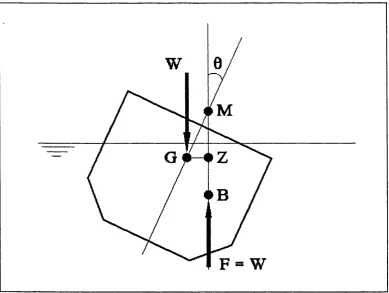
here, together with some o f the most common nomenclature.
The vessel's GZ-Curve is simply a plot o f her static righting arm (or moment) for
a range o f angles o f inclination. In its simplest form, the curve is defined for a
vessel in calm waters, and can be determined in a variety o f means including
experiments with reduced physical models and numerical computation. Figure
2.2 depicts a typical GZ-Curve.
Calculations are usually performed under the assumption o f equilibrium along the
vertical direction, i.e., the vessel's weight W, acting along her centre o f gravity
G, is equalled by the weight o f the displaced water F, which acts along the
centre o f buoyancy B. There is, however, a net moment around the centre of
gravity. This moment is obviously given by Wy^GZ = W x G M x s in ( 9). The
metacentre M is defined as the intersecting point between the vertical through B
and the vessel's centreplane (represented in figure 2.1 by its projection on the
vertical plane). The metacentric height GM is thus defined as the distance
between G and M. The righting arm GZ is just the projection on the horizontal
direction of the metacentric height GM, hence the importance attached to GM as
a measure of the vessel's stability. Clearly, since B can change with the heeling
Chapter Two: Ship Stability Criteria 25
F = W
Figure 2.1 - Hydrostatic forces acting upon a heeled ship
The complete description of the criteria can be found in the Guidance on a
M ethod o f Calculation o f the E ffect o f Severe Wind and R olling in Associated
Sea Conditions (Regulation 31), IMO (1977). We shall reproduce here only the
essential aspects of the criteria.
"The ability o f the vessel to withstand the effects o f gusts and
severe winds and rolling should be demonstrated using dynamic
heeling moment taking into consideration the rolling angle due
to waves. The criterion fo r adequate stability under these
circumstances should show that the effect o f the dynamic
heeling moment (as indicated in figure 2.2) caused by wind
pressure in the worst operating condition, taking into account
the rolling angle, is equal to or less than the effect o f the excess
restoring moment (area "b " or the area under the corresponding
excess restoring arm). This condition is considered to be
Chapter Two: Ship Stability Criteria 26
The ratio C ^r cir^ci "b" / area "a" should not be less than
unity.
Of GZ=
o f
W,
Figure 2.2 - The IMO Weather Criteria
The wind heeling moments (steady and gust) should be calculated by the
following expression;
^ «=1
Where:
= heeling moment due to steady wind
heeling moment due to gust or severe wind
p= air density
Cq= appropriate non-dimensional drag coefficient
K - wind speed factor
K= 1 for steady wind
K>\ for gust wind
Chapter Two: Ship Stability Criteria 27
A = projected lateral profile area of element n
Z = length of wind lever between centroid o f and assumed point of action of
the opposing forces
«= integer
# = number of elements of horizontal areas.
The angles defined in figure 2.2 are:
^0= angle o f heel under action of steady wind
0= angle of roll to windward when rolling about 9^
$2= flooding angle, or angle specified by the Administration.
The values o f K, Z„, 6^, 6^ should be approved by the Administration.
2 .3 Th e G Z - Cu r v e c r i t e r i a: g e n e r a l c o m m e n t s
Although simple in form, the GZ-Curve criteria lend themselves to more
extensive analyses than it is possible to develop here. We shall therefore limit
ourselves to some of the basic aspects and their possible connection with the
study we perform here.
The present IMO criteria have their origins in the work of Rahola (1939), who
collected statistics of 34 capsized vessels between 1871 and 1938. By
considering the characteristics o f those capsized vessels, Rahola proposed
minimum GZ values at different angles o f heeling such that adequate protection
against capsize should be given. The whole method is therefore statistical and
empirical. Later in the 1960s further statistical studies of capsized vessels were
made within the same principle, Nadeinski and Jens (1968), Thomson and Tope
(1970), and the resulting criteria remain almost unchanged to the present day.
Also during the 1960s, the criteria were adapted to provide some cover for
environmental effects, particularly wind, Sarchin and Goldberg (1962), later
Chapter Two: Ship Stability Criteria 28
It seems important to emphasise that, in contrast with the IMO criteria for
passenger and cargo ships, the various parameters and coefficients necessary for
the assessment of the stability characteristics of a fishing vessel through the
criteria shown in 2.2 are not given by IMO, but rather left to be supplied by each
Administration. Therefore the criteria above could be better viewed as a
guideline as to on which grounds to judge the stability o f a given fish in g vessel,
i.e., as a statement that the GZ-Curve is the adequate instrument o f assessing the
stability o f a vessel. It is useful to remember that the requirement o f calculating
and analysing the GZ-Curve was seen as a considerable advance when it was
introduced by IMO. In fact, this requirement is still considered unrealistic for
fishing boats under 24 meters in length. In the Voluntary Guidelines fo r the
Design, Construction and Equipment o f Small Fishing Vessels, IMO (1980), it is
suggested that "where full stability information is not available", a formula for
the minimum initial metacentric height (usually denoted by GM) can be used as a
criterion for adequate stability^.
It should also be noted that vessels are required to fulfil the criteria "in the worst
possible condition". This is intended to cover all operational conditions of a
vessel, particularly with respect to loading conditions and consequent positions
of its centre o f gravity, thereby including the effects o f changes in GM.
Notwithstanding that, the criteria are often regarded as giving inadequate
coverage of light loading conditions, Kuo and Gordon (1975).
In view o f the above, it seems fair to say that the GZ-Curve criterion is more of
a m ethod than a criterion, and it would be convenient to start a critical analysis
of this method by revealing its intrinsic features.
Chapter Two: Ship Stability Criteria 29
The GZ-Curve criteria are a quasi-static energy method. It is based on the idea
that, from a pre-specified initial condition, the vessel should be able to resist a
pre-specified quasi-static wind moment^.
The method is therefore based on what could be called a "standard capsize
event", and the ability of a vessel to withstand that event without capsizing is
regarded as a good measure of its stability qualities. The principle o f defining
appropriate "idealised events" and judging the performance of a system by its
behaviour in such events is widespread in engineering. One reason for that is the
almost infinite variety o f situations in which a system will operate during its life.
It is virtually impossible to test the response o f a system to every combination of
internal and external elements that the system may have to face. The engineering
approach to this problem is to test the system under a few carefully chosen
situations. There are often many procedures that can be used to define test
situations, each one corresponding to a specific method or criterion.
A good example o f the use of idealised events in engineering is the well-
established use of standard tests to define the strength o f materials. In the
laboratory, specimens of pre-specified shapes are subjected to standard
mechanical loads, under which their behaviour is measured and classified. As
parts of real structural systems, materials will never be subjected to precisely the
same loading with which specimens are tested. There are therefore criteria that
relate the two situations, laboratory and real system: if a given material
withstands a mechanical load X as part o f a laboratory specimen, then it will
withstand a mechanical load Y as part o f a given structural system. As we could
expect, the translation of results from laboratory to real structure is far from
straightforward. Some degree of arbitrariness still remains, giving rise to a
variety o f different practical criteria.
Chapter Two: Ship Stability Criteria 30
The case at hand - capsize - is no exception to the rule described above. Even if
the dynamics of a ship in^realistic marine environment could be accurately
modelled, the problem would persist of selecting situations under which to test
the behaviour o f a given vessel. Here again we will find that practical criteria are
based on 'potential capsize' situations. If a given vessel withstands the potential
capsize situation without capsizing, its stability is considered adequate. The IMO
Criteria are based on a potential capsize situation in which a ship is heeled to a
certain angle and then acted upon by a static wind moment o f given magnitude.
A quasi-static calculation is performed in which the work done by the wind
moment has to be equalled by the work done by the vessel's restoring moment
before a certain heel angle is achieved. The definition o f this limit angle is
rather arbitrary. It can be taken as the flooding angle (the angle at which the
vessel starts to accumulate water on deck) or it may be otherwise defined by
local Administration.
Perhaps a more important point to be made here is that the success o f the
approach o f defining idealised events does not seem to be connected to how
accurately the idealised events represent real conditions. In the above example,
the potential capsize situation is clearly very far from actual capsize scenarios.
Large waves, for instance, are a predominant feature o f real capsize scenarios,
and their action is not considered during the energy balance. One may conclude
that the key element here is that the idealised events somehow capture the
'essential features' o f the real phenomena involved. As far as statics go the IMO
Criteria may have captured those essential features. But when trying to
incorporate dynamic effects, a different approach must be devised. Here we
believe that nonlinear dynamics may have an important role to play, for without
studies on the dynamical mechanisms involved in large-amplitude motions and
capsize there is little hope of achieving a better understanding o f what the
essential features o f the problem are.
In this respect, some obvious shortcomings o f the IMO Criteria should perhaps
Chapter Two: Ship Stability Criteria 31
the method is supposed to work upon, and by the requirement o f keeping its use
very simple (see Vassalos (1985) ).
1. Strong winds are indeed a common feature in capsize scenarios, and the
method rightly considers their action. But strong winds are frequently associated
with large waves, whose effects are not given the same treatment in the method.
2. The waves that caused the ship to roll up to an angle 6^ from which the gust
wind is then supposed to act are not considered in the subsequent calculations.
3. Because no dynamic (time-related) effect is included, no consideration can be
given to the oscillatory nature o f some important capsize mechanisms.
4. Due to its empirical nature the method gives little or no information about
"safety factors" eventually involved, which could be thought of as partially
taking care o f dynamic and waves effects.
These aspects are reflected in the general feeling among researchers that waves
and dynamic effects are not adequately dealt with by the existing methods (see
section 2.1). The question is clearly how to add dynamic effects to the analysis
without making it too complicated to apply in practice. The answer seems to be
made more difficult by the fact that, as it is now known, the behaviour of simple
dynamical systems used to describe the most basic features of ship motion can be
extremely complex. We hope, however, to show that the same methods that
helped researchers to unveil the subtle complexities o f dynamical models o f ship
motion can help them to synthesise new stability criteria o f better quality, and
simplicity compatible with present computational resources.
2 . 4 B r i e f s u r v e y o f w o r k s o n s h i p s t a b i l i t y c r i t e r i a
The literature on ship stability and stability criteria is considerable, and
Chapter Two: Ship Stability Criteria 32
have been used in attempts to tackle the problem o f producing simple yet
comprehensive methods to assess the stability qualities o f marine vessels.
There is a strong feeling among a number of researchers that a probabilistic
approach must be used. This feeling seems to stem from the assertion that both
the marine environment and ship operational conditions are too varied and
unpredictable to allow the use of deterministic methods. Therefore a large
number o f works adopt a probabilistic approach, in which the capsizability o f the
vessel is measured as a probability of failure under a design excitation defined in
terms o f its statistical properties. See for instance Boroday and Nikolaev (1975),
Huang (1990), Kaplan (1990), Kastner (1975), Kobylinski (1975), Tikka and
Pauling (1990), Umeda et al (1990).
Research on improved stability criteria has been carried out for many years at
Strathclyde University. As a result, new criteria have been proposed in which the
effect o f waves is explicitly taken into account, see for instance Martin et al
(1982), Vassalos (1985), and Kuo et al (1986). In essence, this criterion is based
on the idea o f performing an energy balance between exciting and restoring
forces along a carefully chosen critical cycle o f oscillation. The main
contribution o f this method is to allow for the inclusion in the calculations o f
time-varying moments. Although a systematic procedure for the location o f
critical conditions is included in the method, a certain degree o f arbitrariness
remains. Furthermore, being a quasi-dynamic method, the Strathclyde criteria
allow for limited inclusion o f dynamic effects.
In a series o f papers, L. Virgin has put forward a simplified criterion for stable
ship roll motions in regular waves. Virgin (1987, 1989, 1990). His approach
resembles our own in the selection of deterministic dynamics in phase space as
the main tool for assessing ship stability. He proposes a criterion based on a
comparison between the total mechanical energy of a limiting state of the ship
(say, the ship heeled to the angle of vanishing stability) and the energy o f
trajectories. He argues that if the total energy o f motion along a steady-state
Chapter Two: Ship Stability Criteria 33
safety factor defines exactly how much below the critical value the trajectories'
energies should remain. The main limitation of Virgin's work may be its reliance
on steady-state dynamics. As we shall see, the stability o f steady-state
trajectories can be a misleading parameter upon which to base ship stability
analyses.
Work being carried out at the Centre for Nonlinear Dynamics of the University
College London by J.M.T. Thompson and colleagues has employed an approach
inspired in modern methods of nonlinear dynamics, where analytical and
computational investigations combine to produce both qualitative and
quantitative assessments of the dynamical behaviour o f vessels in regular waves.
These methods follow on a long tradition initiated by Henry Poincaré, who in the
beginning o f this century advocated the use of phase space representations as a
valuable tool in the construction o f our understanding o f complex nonlinear
dynamical systems, Poincaré (1899).
Following detailed studies o f the behaviour o f transient and steady-state motions
of archetypal mathematical models o f ship motion under the action of regular
waves, Thompson and co-workers have proposed a remarkably simple method to
assess ship stability against capsize. The method is based on the construction of
a plot o f critical amplitudes of forcing against the frequency o f the forcing, the
Transient Capsize Diagram, see for instance Rainey et al (1990), and Rainey and
Thompson (1991).
The backbone o f this method is the finding that, under quite general conditions,
the loss o f engineering integrity o f a ship is dominated by a rapid erosion"^ of its
safe basin o f attraction, Thompson et al (1990), Soliman and Thompson (1992).
The authors propose that the values o f forcing parameters at which such erosion
starts can be approximately determined through a series o f experiments
(numerical or physical) in which the ship is excited fro m rest by short trains of
regular waves. The objective of the experiments is to determine the minimum
Chapter Two: Ship Stability Criteria 34
amplitude o f excitation for escape (capsize) at each frequency within the range
of interest. The domain of safe initial conditions (the safe basin o f attraction) has
been shown to be swiftly eroded by fractal incursions after a series of homoclinic
events (bifurcations), making the particular choice o f starting conditions
relatively irrelevant, Soliman and Thompson (1989). Stable steady-state
solutions can, however, persist within the safe basin fo r considerably larger
levels o f excitation. This makes analyses based on the stability o f steady-state
solutions dangerously non-conservative.
Our own work is part o f the effort just described, and is intended to contribute
to the research along similar lines tackling some of the points open to further
Chapter Three: M athematical M odelling 35
3. M A T H E M A T IC A L M O D ELLIN G OF SH IP M OTION
This chapter introduces mathematical models o f ship motions. We give a
brief overview o f this vast subject, and proceed to describe in more detail the
specific models we shall be using in this work.
3 .1 Ob j e c t i v e o f m a t h e m a t i c a l m o d e l l i n g
The purpose o f a mathematical model is to represent interesting aspects of
a phenomenon. Real problems are usually too complex to allow the definition of
a mathematical model that represents all interesting aspects involved. Choices
are therefore necessary, and the mathematical models we use are the result of a
number o f choices that privilege some factors whilst leaving others aside. The
representation of the problem of a marine vessel moving in the sea through
mathematical formulae is a prime example o f that.
As a consequence o f the complexity of the problem, mathematical models o f ship
motion tend to be rather specialised. We shall be dealing here with a small subset
o f mathematical models o f ship motion directly concerned with ship capsize.
Other classes o f models exist which find use in different problems, including
seakeeping, manoeuvrability, and structural design.
For our purposes the problem of ship motions can be phrased as follows. We
imagine a marine vessel freely floating at sea under the action o f wind and
waves. We are solely concerned with the behaviour o f the vessel as a rigid body.
More specifically, we want to investigate under which conditions the vessel will
display large-amplitude motions that can lead to capsize. We start with a brief
Chapter Three: M athem atical M odelling 36
3 .2 Ba s i c s h i p c a p s i z e m e c h a n i s m s i n w a v e s
The physical mechanisms through which a vessel in waves can experience
large-amplitude motions and eventual capsize form the basis o f most efforts to
model the problem mathematically. Simplified mathematical models in particular
usually concentrate on one or two possible physical mechanisms. In what follows
we present a well accepted classification o f ship capsize mechanisms, and we
establish a correlation between those mechanisms and typical mathematical
models.
The U.S. Coast Guard mounted in the early 1970s a five-year program o f trials
with ship models in open water. The main goal was to achieve good
understanding o f the physical basis of ship stability in waves, and the then
proposed classification o f capsize mechanisms is still a landmark in the subject,
see Paulling et al (1975). To their classification we add here a further
mechanism, namely capsize in beam seas. This well known mechanism was not
included in the work o f Paulling and others probably based on the assumption
that, in general, ship’s heading can be adjusted to avoid prolonged exposure to
beam waves.
Two reasons, however, make it desirable to take that unfavourable scenario into
account. Firstly, the number of waves necessary to induce large roll angles or
even capsize can be quite small, and is not known a priori. Numerous reports of
real capsize events indicate that capsize can occur when the vessel is subjected
to a short train o f large waves, see for instance Kowaslky (1985) and National
Research Council (1991). Thus, in practical situations the time for the crew to
manoeuvre the ship and therefore avoid large amplitude motions can be short.
Secondly, operational requirements sometimes make it difficult or undesirable
for the ship to change course during considerable lengths o f time’. Although
seakeeping considerations should determine the temporary disruption of normal