IJEDR1702130 International Journal of Engineering Development and Research (www.ijedr.org) 779 Abstract— this project presents a single phase transformer less inverter topology for grid-connected photovoltaic (PV)
and wind energy systems which is capable of solving leakage current issues. In this further work, the ground leakage current is controlled within the regulation limit by using LC filter. The proposed system can inject both active and reactive power into the utility grid without current distortion and leakage current. The MPPT algorithm control strategy is used in PV module to harvest the peak possible power from the module, even though they might be at divergent irradiance levels and operating temperature. Wind power module is also controlled by MPPT algorithm in an effective way.A detailed analysis is carried out on the hybrid system at desired conditional parameters such as irradiation, temperature etc.
Index Terms—Converter,leakage current, PV array, tansformerlessinverter, wind turbine.
1. INTRODUCTION
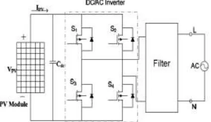
In order to ensure the safety, leakage currents must be the smaller the better in grid-connected PV systems. Using the transformers can ma ke the galvanic connection between the grid and the PV array eliminated. But the transformer is large, heavy, and expensive. Thus, finding a way of high efficiency, low price, light weight, small volu me is necessary. The transformer less inverter with low leakage currents can solve the problem in grid -connected PV systems, particularly in low -power single-phase systems. So various transformer less inverter topologies have been proposed to meet the point of reducing leakage currents by experts around the world.
The full bridge circuit high frequency common-mode equivalent model, and pointed out the way to eliminate leakage currents is the freewheeling voltage is half of the input voltage. Based on the conclusion, the leakage currents of the topologies can be dimin ished in the following aspects: a) Creat ing a freewhee ling current path, b) Neutral point clamped. In fact, the freewheeling currentdirections is reversed in different half period of the utility grid. This paper proposes a novel structure based on the idea which is able to create a path can only flow the positive freewhee ling current in the positive half period figure 1, and flow the negative freewheeling current in the negative half period respectively, so that it achieve the point of the freewheeling currents directions separation by the IGBTs and diodes.
This paper will first introduce the leakage path for transformer less PV systems. Then the comparative analysis on the proposed topology and Heric topology is described. Finally, the simulat ion
results are presented to prove the well performance of the proposed topology in lea kage currents.
Figure 1. Block diagram of proposed system
2. LEAKAGE CURRENTS IN TRANSFORM ERLESS PV SYSTEM S
Illustrations Fig. 2[16] shows the proposed transformer less inverter topologies consisting of six IGBT switches (S1-S6) and six d iodes. It is a resonant circuit where the PV is grounded. Leakage current flows between the PV and the grid when the transformer is re moved from the PV inverter. The behavior of leakage ground current is strongly subjective to the converter topology and the PWM strategy. It includes parasitic capacitance (CPE), each connected between the positive (P) and negative (N) of the PV to the ground, the filter inductance (Lc), and the ground resistance (Rf) [16]. In three-phase PV system, the common -mode (CM) and diffe rential mode (DM) voltages between each phase are similar phase a and b, phase b and c, phase c and a. Therefore, the analysis of phase a and b is suffic ient to represent the rema ining of the phases.
To the full-bridge inverter, without transformer, a ga lvanic connection between the ground of the grid and the PV array e xists. Therefore,
Grid-ConnectedPV-Wind
SystemwithImplementation of Transformerless
Inverter
C.MONICA, R.ARULMOZHIYAL
IJEDR1702130 International Journal of Engineering Development and Research (www.ijedr.org) 780 the leakage current is flowing through path inclu ding
L1, L2, Cpv1, Cpv2, Zgand Bridge. As shown in Fig.2, The leakage current path is simplified to an LC resonant circuit. The common-mode voltage (udm) in the Fig.3 is defined as:
Figure 2. Proposed full bridge transformerless inverter
Figure 3. Leakage currents in a transformer less conversion stage
𝑈𝑑𝑚 =
𝑈𝐴𝑁+ 𝑈𝐵𝑁
2 (1)
uAN is the voltage between point A and point N, uBN is the voltage between point B and point N. The inductors L1 and L2 can be with the equal value easily. As a result, a conclusion can be given that when the CM voltage keeps constant, the leakage currents will be e liminated.
3.OPERATINGPRINCIPLE
In this section, a comprehensive survey of state-of-the-art asymmetrica l inductor based transformerless inverters (L1=0 or L2=0) is presented and discussed. The reviewed topologies are classified into the follo wing sub-groups: half-bridge inverters, dual-buck inverters, v irtual DC bus inverters, line-frequency unfolding topologies and Karschny transformer less inverter.
A. Half-Bridge Transformerless Inverters
Assuming L2=0 and termina l N is directly connected to terminal 2 in Fig. 1, the total high-frequency common mode voltage is zero without high frequency leakage current. Genera lly speaking, the conventional two-level half-bridge inverter [in Fig. 3 (a)] can eliminate the leakage current with simp lified configuration because only two power switches and one inductor are required [50]. However, the DC-link voltage should be twice of the grid peak voltage and the semiconductors should sustain the high DC-link voltage stress. Moreover, the bipolar inverter output voltage increases the filter
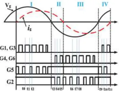
size and cost.Fig 4[1], where G1, G2, G3, G4, G5, and G6 represent the gate drive signals of the switches S1, S2, S3, S4, S5, and S6, respectively. The circuit d iagra m for negative half cyc le operation is depicted.
Figure 4. Various types of bridge level converter
IJEDR1702130 International Journal of Engineering Development and Research (www.ijedr.org) 781 Figures 4. The operating princ iple of Transformerless
inverter (a ) state 1 (b) state 2 (c) state 3 (d) state 6
4. HIGH FREQUENCY CM M ODEL OF THE PROPOSED TOPOLOGY FOR LEA KA GE
CURRENT ANA LYSIS
The PV module generates an electrically chargeable surface area which faces a grounded frame. In case of such configuration, a capacitance is formed between the PV module and the ground. Since this capacitance occurs as an undesirable side effect, it is referred as parasitic capacitance. Due to the loss of galvanic separation between the PV module and the grid, a CM
Resonant circuit can be created. An alternating CM voltage that depends on the topology structure and control scheme, can electrify the resonant circuit and may lead to higher ground leakage current [6], [16], [22]. In o rder to analyze the CM characteristics, an equivalent circuit of the proposed topology as shown in Fig. 5 can be drawn, where V1N,V2N,V3N and V4N a re the controlled voltage source connected to the negative terminal N, LCM and CCM a re the CM inductor and capacitor,During the positive half-cycle, the switches S4 and S6 are a lways off. As a result, the controlled voltage sources V3N and V4N are zero and can be removed. According to the definition of common-mode and differentia l-mode voltage:
Figure 5.Equiva lent CM mode l of the proposed topology
𝑉
𝑐𝑚=
12
(𝑉
𝑁1+ 𝑉
𝑁2)
(2)
𝑉
𝐷𝑚= 𝑉
𝑁1− 𝑉
𝑁2(3)
𝑉
𝑁1= 𝑉
𝐶𝑀+
12
𝑉
𝐷𝑀(4)
𝑉
𝑁2= 𝑉
𝐶𝑀−
12
𝑉
𝐷𝑀(5)
In order to illustrate the CM mode l at switching frequency, equation (4) and (5) could be replaced for the bridge-leg in Fig. 6. The grid is a low frequency (50–60 Hz) vo ltage source.
Figure 5. Equivalent CM model o f the proposed topology
Figure 6.Simp lified single loop CM mode l. The DM capacitor Co can also be removed since it has no effect on the leakage current. Consequently, the simplified high frequency CM model of the proposed topology for positive half-cycle could be drawn as Fig. 5. Finally, the simp lified single loop CM model of the proposed topology for positivehalf cycle is derived in Fig. 6.
𝑉𝑡𝐶𝑀 = 𝑉𝐶𝑀 + 𝑉𝐷𝑀
2 𝐿2−𝐿1
𝐿2+ 𝐿1 (6) Where,VtCMrepresent total CM voltage, and L1 = L1A + L1g and L2 = L1B + L2g. In the proposed inverter if L1A = L1B and L1g = L2g for a we ll-designed circuit with symmetrically structured magnetics, equation (6)
5. Control o f the proposed topology
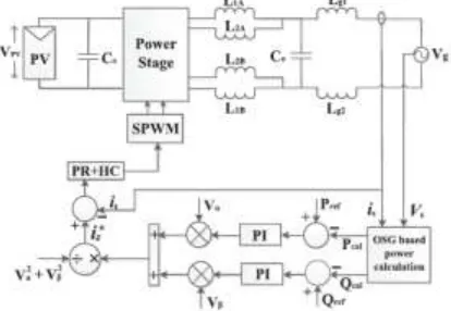
IJEDR1702130 International Journal of Engineering Development and Research (www.ijedr.org) 782 Figure 7. Control diagra m of the proposed topology
Figure 8. OSG based power calculation
In order to control the grid current, several e xisting control methods such as conventional PI controller, repetit ive controller (RC), proportional resonant (PR) controlle r, and deadbeat (DB) controller can be adopted due to the capability of tracking re ference signal without steady state error [27], [28]. Since the PR controller has better performance of tracking the reference signal if compared to the norma l PI and RC controller, it is selected to control the output current of the proposed topology.
5. SIM ULATION RESULTS
The transformer less inverter was simulated using MATLAB/SIM ULINK tool. The PV ce ll and wind module were designed and simulated with the help of its equivalent circuit. Te mperature and irradiation were considered as the changing parameters to change the output of the solar cell. The PV cells of 24V were taken as input for the transformer less inverter. The dc/dc boost converter is used to boost up the obtained dc input voltage to desirable value. The configured transforme r less inverter network does boost operation and reduces the third level harmonic content. The inverter converts dc single in to ac. The switching circuit consists of six IGBTs and diodes which are ta ken fro m Simu link lib rary. A LC filter is used to connect the inverter to the load side. The switching sequences were provided according to the operation described above. A 385V voltage and 20 A current waveform was obtained as output for the gird. The output
voltage from PV array is obtained by keeping its irradiance value constant at 1000W/ m2.Fig 9 shows the output wave of PV array with MPPT controller of irradiance level 3W/ m2. Output power and voltage ma intains at 28W and 20V respectively. Fig 10.1 & 10.2 shows the output waveform of wind output voltage is ma intained at 15V a long with the MPPT controller. Fig : 11 shows the boost converter output is maintained at 40V for which the battery current is 0.4A. Fig : 11 shows the increase of battery voltage to 21.98V fo r current decreases gradually below zero ampere .Transformerless inverter output voltage of 100V for wh ich reduced leakage current of 21V is obtained as Output of phase and line voltage of inverter here the voltage value is 230V,50Hz nominal frequency . Input current and output voltage of the transformer less inverter is measured and the resultant waveform. Fro m wind, the output power is 5W. Load receives 50kW supply. Thus the overall three phase output voltage is 320V and output current of 20A.
Figure 9. PV voltage with MPPT controller and PV output
IJEDR1702130 International Journal of Engineering Development and Research (www.ijedr.org) 783 Figure 10.1. Output waveforms of battery and boost
converter
Figure 11. Waveforms of Output power fro m PV, Wind, Battery and Load
6. CONCLUSION
A transformer less inverter for grid connected hybrid system was simulated using MATLAB/SIMULINK tool. Th is three-phase transformer inverter was capable of obtain a ma ximu m possible power fro m solar and wind module. Incre mental conductance MPPT technique was used. Therefore, the PV string can be of different electrica l para meters and working conditions. Transforme rless condition of the inverter helped the system to convert ma ximu m output power fro m the hybrid system to the gird by limiting pulsating power. Lea kage Current was reduced by placing LC filter across the output of the inverter. LC filter also reduced the harmonics produce at inverter output voltage. Output power was subjected to active and reactive power compensation. Three phase output voltage of 320 V, 20 A was obtained. A 1kW prototype of PV and 7 W of wind was built and tested through simu lation. The control scheme of transformer less inverter topology was described, and its detailed analysis was provided. Several e xperimental results were also shown to confirm the validity of the proposed inverter.
REFERENCES
[1] Monirul Islam, Nadia Afrin, and SaadMekhilef “Efficient Single Phase Transformerless Inverter for Grid-T ied PVG System With Reactive Power Control” IEEE transactions on sustainable energy, vol. 7, no. 3, July 2016
[2] Yi Tang ,Wenli Yao , Poh Chiang Loh , and FredeBlaabjerg “Highly Reliable Transformerless Photovoltaic Inverters with Leakage Current and Pulsating Power Elimination” IEEE transactions on industrial electronics, vol. 63, no. 2, February 2016.
[3] Wuhua Li , YunjieGu , HaozeLuo , Wenfeng Cui , Xiangning He and Changliang Xia “Topology Review and Derivation Methodology of Single-Phase Transformerless Photovoltaic Inverters for Leakage Current Suppression” ieee transactions on industrial electronics, vol. 62, no. 7, July 2015
[4] AbhishekGarg, Rajasekar.S,and Rajesh Gupta,”A New Modulation T echnique to EliminateLeakage Current in Transformerless PV Inverter”
[5] K. S. F. Tan, N. A. Rahim, H. Wooi-Ping, and C. Hang Seng, "Modulation T echniques to Reduce Leakage Current in Three-Phase T ransformerless H7 Photovoltaic Inverter," Industrial Electronics, IEEE Transactions on, vol. 62, pp. 322-331, 2015.
[6] T. Kerekes, R. Teodorescu, and U. Borup, Transformerless photovoltaic inverters connected to the grid,” in Proc. APEC, Feb. 25–Mar. 1, 2007, pp. 1733–1737.
[7] E. Ün, and A. M. Hava, “A near-state PWM method with reduced switching losses and reduced common-mode voltage for three-phase voltage source inverters,” IEEE Trans Ind. Appl., vol. 45, no. 2, pp.782-793 , Mar./Apr. 2009.
[8] Y. Bo, L. Wuhua, G. Yunjie, C. Wenfeng, and H. Xiangning, “Improved transformerless inverter with common-mode leakage current elimination for a photovoltaic grid-connected power system,” IEEE Trans. PowerElectron., vol. 27, no. 2, pp. 752–762, Feb. 2012.
[9] E. Gubía, P. Sanchis, A. Ursúa, J. Lopez, and L. Marroyo, “Groundcurrents in single-phase transformerless photovoltaic systems,” Prog. Photovolt., Res. Appl., vol. 15, no. 7, pp. 629–650, 2007.
[10] Lopez.O, T eodorescu.R, Freijedoy.J, "Eliminating ground current in a transformerless photovoltaic application," IEEEPowerdo.F, Doval-Gan Engineering Society General Meeting, 2007. , vol., no., pp.1-5, 24-28 June 2007. [11] Agelidis.V.G, Baker.D.M, Lawrance.W.B, Nayar.C.V, "A
multilevel PWM inverter topology for photovoltaic applications," Proceedingsof the IEEE International Symposium on Industrial Electronics, 1997.ISIE '97, vol.2, no., pp.589-594 vol.2, 7-11 Jul 1997.
[12] S. Dasgupta, S. K. Sahoo, and S. K. Panda, “Single-phase inverter control techniques for interfacing renewable energy sources with micro grid partI : Parallel-connected inverter topology with active and reactive power flow control along with grid current shaping,” IEEE Trans. PowerElectron., vol. 26, no. 3, pp. 717–731, Mar. 2011.
[13] F. Blaabjerg, R. T eodorescu, M. Liserre, and A. V. Timbus, “Overview of control and grid synchronization for distributed power generation systems,” IEEE Trans. Ind. Electron., vol. 53, no. 5, pp. 1398–1409, Oct. 2006.
[14] W. Yong and L. Rui, “Novel high-efficiency three-level stacked-neutralpoint - clamped grid-tied inverter,” IEEE Trans. Ind. Electron., vol. 60, no. 9, pp. 3766–3774, Sep. 2013.