Int. J. of Engg. Sci. & Mgmt. (IJESM), Vol. 1, Issue 1: Sep. - Dec. 2011, 55-63
INTERNATIONAL JOURNAL OF ENGINEERING SCIENCES
&
MANAGEMENT
AUTOMATIC GENERATION CONTROL OF MULTI AREA INTERCONNECTED THERMAL POWER SYSTEM CONSIDERING ASYNCHRONOUS TIE-LINES
Yogendra Arya1, Narendra Kumar2, and Narendra Hooda*3
*1
Department of Electrical and Electronics Engineering, Maharaja Surajmal Institute of Technology, C-4, Janakpuri, New Delhi, India
2
Department of Electrical Engineering, Delhi Technological University, Delhi, India
3
Deenbandhu Chhotu Ram University of Science & Technology, Murthal, Sonepat, India
ABSTRACT
This paper investigates the effects of HVDC tie-line in parallel with HVAC tie-line on automatic generation control (AGC) problem for a multi-area power system taking into consideration system parameter variations. A fuzzy logic controller is used for five area power system interconnected via parallel HVAC/HVDC transmission link which is also referred as asynchronous tie-lines. The linear model of HVAC/HVDC link is developed and the system responses to sudden load change are studied. Suitable solution for automatic generation control problem of five area electrical power system is obtained by means of improving dynamic performance of power system under study. Robustness of controller is also checked by varying parameters. Simulation results indicate that the scheme works well. The dynamic analyses have been done with and without HVDC link using fuzzy logic controller in MATLAB/SIMULINK. Further a comparison between the two is presented and it has been shown that the performance of the scheme under study is superior in terms of overshoot and settling time.
Keywords: Automatic generation control, fuzzy logic controller, HVAC/HVDC transmission
link, generation rate constraint
INTRODUCTION
The automatic generation control is a technical requirement for the proper operation of interconnected power systems. For large scale electrical power systems that normally consist of interconnected control areas representing coherent groups of generators, automatic generation control is very important in power system operation and control for supplying sufficient and reliable electric power with good quality.
Corresponding Author*
Email- [email protected]
Int. J. of Engg. Sci. & Mgmt. (IJESM), Vol. 1, Issue 1: Sep. - Dec. 2011, 55-63
generation levels should satisfy the optimal
dispatch conditions. Some intelligent
controllers have been proposed to solve
these problems but considering area
interconnection with ac line [1-4]. Also
fast-acting energy storage systems e.g.
superconducting magnetic energy storage [5], battery energy storage [6], super-capacitor bank [7] etc., can effectively damp electromechanical oscillations in a power system, because they provide storage capacity in addition to the kinetic energy of the generator rotors which can share sudden changes in power requirement. A little attention has been paid to use of HVDC transmission link as system interconnection. Majority of the work carried out earlier is centered on interconnected power systems considering the area interconnection with ac tie lines only. However, there has been a
tremendous growth of the HVDC
transmission system due to economic, environmental and performance advantages over the other alternatives Hence it has been applied widely in operating a dc link in parallel with an HVAC link interconnecting control areas to get an improved system dynamic performance with greater stability margins under small disturbances in the system [8-12]. A favorable effect on system dynamic performance has been achieved considering such system interconnection. These studies are carried out considering the nominal system parameter values after linearization of the system about an operating condition. In practical cases, system parameters do not remain constant and continuously vary with changing operating conditions. Therefore, a serious concerned should be given to these parameter variation [13-14]. Because of complexity and multi-variable conditions of the power system, conventional control methods may not give satisfactory solutions. On the other hand robustness and reliability
makes fuzzy controllers useful in solving wide range of control problems including AGC of interconnected power system [15-20].
In the present paper a fuzzy logic controller is designed and implemented to analyze the dynamic performance of five unequal area thermal power system, interconnected with HVAC/HVDC parallel link taking parameter uncertainties into account. The simulation
results are presented to show the
effectiveness of the scheme.
FIVE AREA POWER SYSTEM
The five area power system model identified in the present study has the following configuration:
a) It is a five unequal area system of area1:
2000 MW, area2: 4000 MW, area3: 8000 MW, area4: 10,000MW, and area5: 12,000MW.
b) The five areas are interconnected via
HVAC tie line in parallel with HVDC link.
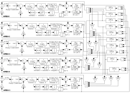
The single line diagram of the model under consideration for two areas is presented in Fig. 1 and the block diagram of five area interconnected system with HVDC link is described in Fig. 2. The transmission links are considered as long transmission lines specifically of length greater than break even distance length of HVAC and HVDC transmission lines [8].
Int. J. of Engg. Sci. & Mgmt. (IJESM), Vol. 1, Issue 1: Sep. - Dec. 2011, 55-63
system studies [22]. An equal bias (Bi)
setting is considered for all areas. The step load perturbation (SLP) of 1-10% of the nominal loading has been considered in either of the area for system analysis. The system parameters are given in the
appendix. Fig. 1. Single line diagram of two area out of five
area power system with HVAC/HVDC parallel tie-line
Fig. 2. Block diagram of five area interconnected system
FUZZY LOGIC CONTROLLER
Fuzzy set theory and fuzzy logic establish the rules of a nonlinear mapping [23]. The use of fuzzy sets provides a basis for a systematic ways for the application of uncertain and indefinite models. Fuzzy control is based on a logical system called
Int. J. of Engg. Sci. & Mgmt. (IJESM), Vol. 1, Issue 1: Sep. - Dec. 2011, 55-63
The main goal of AGC in interconnected power systems is to protect the balance between production and consumption. The fuzzy logic controller designed for the system analysis is shown in Fig 3.
Fig 3. Structure of fuzzy logic controller
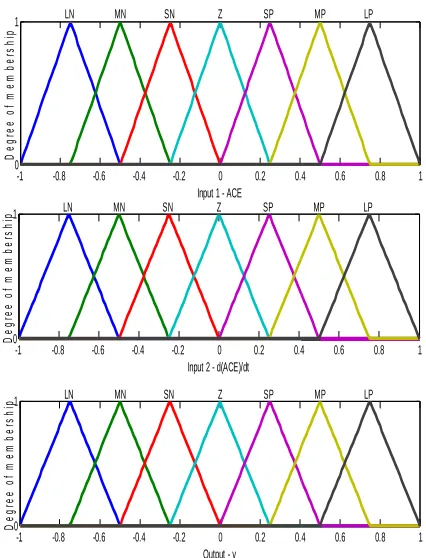
In this study derivative of area control error together with area control error (ACE) are fed to the fuzzy logic controller. The fuzzy controller block is formed by fuzzification of ACE and derivative of ACE, the inference mechanism and defuzzification. Therefore, y is a crisp value and u is a control signal for the system. Centroid method of defuzzification and Mamdani fuzzy theory is applied in determining the gains of controller. Table I presents the rules for fuzzy logic controller. There are 7 triangular membership functions considered for inputs (ACE and derivative of ACE) and one output (y). Total 49 rules are designed to get the response. The membership functions used in the fuzzy controller are presented in Fig. 4.
-1 -0.8 -0.6 -0.4 -0.2 0 0.2 0.4 0.6 0.8 1 0
1
Input 2 - d(ACE)/dt
D
e
g
re
e
o
f
m
e
m
b
e
rs
h
ip LN MN SN Z SP MP LP
-1 -0.8 -0.6 -0.4 -0.2 0 0.2 0.4 0.6 0.8 1 0
1
Input 1 - ACE
D
e
g
re
e
o
f
m
e
m
b
e
rs
h
ip
LN MN SN Z SP MP LP
-1 -0.8 -0.6 -0.4 -0.2 0 0.2 0.4 0.6 0.8 1 0
1
Output - y
D
e
g
re
e
o
f
m
e
m
b
e
rs
h
ip LN MN SN Z SP MP LP
Fig. 4. Membership functions used in the study Table I. Rules for the fuzzy logic controller
d(ACE)/dt
L N
M N
SN Z SP M
P LP
A
C
E
L N
LP LP LP M
P M
P
SP Z
M N
LP M
P M
P M
P
SP Z SN
S N
LP M
P
SP SP Z SN M
N
Z M
P M
P
SP Z SN M
N M
N
SP M
P
SP Z SN SN M
N LN
M P
SP Z SN M
N M N
M N
LN
L P
Z SN M
N M N
LN LN LN
Int. J. of Engg. Sci. & Mgmt. (IJESM), Vol. 1, Issue 1: Sep. - Dec. 2011, 55-63
SIMULATION RESULTS
In this paper, a fuzzy logic controller has been designed and applied to an unequal five area thermal power system consisting of
single stage reheat turbines. The
implementation worked with MATLAB-SIMULINK software. The same values of system parameters [8, 9] given in appendix, are used for all simulations to facilitate a comparative study.
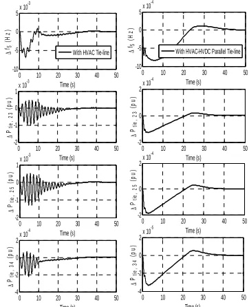
The response plots for variables like frequency deviations in area 1 to area 5 and some tie-line power deviations for power system model with and without HVDC link in parallel with HVAC tie-line, in the wake of load disturbance of 1% in area 1, are obtained with the implementation of fuzzy logic controller to analyze the system dynamic performance as shown in Figs. 5 and 6. Fig. 7 shows the frequency deviation of area 1, area 2 and generated power
deviations of ∆Pg2 and ∆Pg5 with higher
values of step load perturbation (SLP) applied in various areas simultaneously (i.e.
∆Pd1= 0.1 pu, ∆Pd2 = 0.02 pu, ∆Pd3 = 0.03
pu, ∆Pd4 = 0.01 pu, and ∆Pd5= 0.01 pu).
0 10 20 30 40 50 -0.02 -0.01 0 0.01 Time (s) ∆ f1 ( H z )
0 10 20 30 40 50 -0.02 -0.01 0 0.01 Time (s) ∆ f2 ( H z )
0 10 20 30 40 50 -10
-5 0 5x 10
-3 Time (s) ∆ f3 ( H z )
0 10 20 30 40 50 -10
-5 0 5x 10
-3 Time (s) ∆ f4 ( H z )
0 10 20 30 40 50 -10
-5 0 5x 10
-4 Time (s) ∆ f4 ( H z )
0 10 20 30 40 50 -10
-5 0 5x 10
-4 Time (s) ∆ f3 ( H z )
0 10 20 30 40 50 -2
-1 0 1x 10
-3 Time (s) ∆ f2 ( H z )
0 10 20 30 40 50 -0.02 -0.01 0 0.01 Time (s) ∆ f1 ( H z )
With HVAC-HVDC Parallel Tie-line HVAC Tie-line
Fig. 5. Frequency deviation of area 1to area 4 with
∆Pd1 = 0.01 pu
0 10 20 30 40 50 -10
-5 0 5x 10
-4 Time (s) ∆ f5 ( H z )
0 10 20 30 40 50 -2
0 2x 10
-4 Time (s) ∆ Ptie , 2 3 ( p u )
0 10 20 30 40 50 -2
0 2x 10
-4 Time (s) ∆ Ptie , 2 5 ( p u )
0 10 20 30 40 50 -4
-2 0 2x 10
-5 Time (s) ∆ Ptie , 3 4 ( p u )
0 10 20 30 40 50 -4
-2 0 2x 10
-4 Time (s) ∆ Ptie , 3 4 ( p u )
0 10 20 30 40 50 -2
-1 0 1x 10
-3 Time (s) ∆ Ptie , 2 5 ( p u )
0 10 20 30 40 50 -2
-1 0 1x 10
-3 Time (s) ∆ Ptie , 2 3 ( p u )
0 10 20 30 40 50 -10
-5 0 5x 10
-3 Time (s) ∆ f5 ( H z )
With HVAC Tie-line With HVAC-HVDC Parallel Tie-line
Fig. 6. Frequency deviation of area 5 and tie-line
power deviations of ∆Ptie, 23 pu, ∆Ptie, 25 pu, and
∆Ptie, 34 pu with ∆Pd1 = 0.01pu
0 50 100 150 200 250 300 -0.2 0 0.2 Time (s) ∆ f1 ( H z )
0 50 100 150 200 250 300 -0.04 -0.02 0 0.02 Time (s) ∆ f2 ( H z )
0 50 100 150 200 250 300 0 0.01 0.02 0.03 Time (s) ∆ Pg 2 ( p u )
0 50 100 150 200 250 300 -0.01 0 0.01 0.02 Time (s) ∆ Pg 5 ( p u )
0 50 100 150 200 250 300 0 0.01 0.02 0.03 Time (s) ∆ Pg 5 ( p u )
0 50 100 150 200 250 300 0 0.01 0.02 0.03 Time (s) ∆ Pg 2 ( p u )
0 50 100 150 200 250 300 -2 -1 0 1 Time (s) ∆ f2 ( H z )
0 50 100 150 200 250 300 -2 -1 0 1 Time (s) ∆ f1 ( H z )
With HVAC Tie-lin
With HVAC-HVDC Parallel Tie-lin
Fig. 7. Frequency deviation of area 1, area 2 and
generated power deviations of ∆Pg2 and ∆Pg5 with
∆Pd1 = 0.1 pu, ∆Pd2 = 0.02 pu, ∆Pd3 = 0.03 pu, ∆Pd4
Int. J. of Engg. Sci. & Mgmt. (IJESM), Vol. 1, Issue 1: Sep. - Dec. 2011, 55-63
0 20 40 60 80 100 -0.2 0 0.2 Time (s) ∆ f1 ( H z )
0 20 40 60 80 100 -0.2 0 0.2 Time (s) ∆ f2 ( H z )
0 20 40 60 80 100 0 0.005 0.01 0.015 Time (s) ∆ Pg 4 ( p u )
0 20 40 60 80 100 -0.01 0 0.01 0.02 Time (s) ∆ Pg 5 ( p u )
0 10 20 30 40 50 -4
-2 0 2x 10
-3 Time (s) ∆ Pg 5 ( p u )
0 10 20 30 40 50 0 0.005 0.01 0.015 Time (s) ∆ Pg 4 ( p u )
0 10 20 30 40 50 -0.02 -0.01 0 0.01 Time (s) ∆ f2 ( H z )
0 10 20 30 40 50 -0.02 -0.01 0 0.01 Time (s) ∆ f1 ( H z )
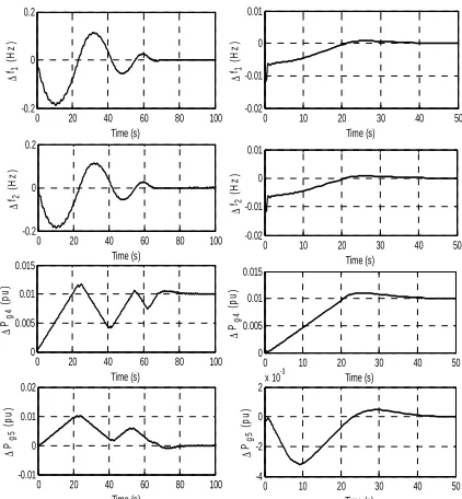
Fig. 8. Frequency deviations of area 1 (∆f1), area 2
(∆f2), and generated power deviations of area 4
(∆Pg4), and area 5 (∆Pg5) with +10% of nominal
values of Bi, Tpi and Tij with ∆Pd1 = ∆Pd2 = ∆Pd3 =
∆Pd4 = 0.01 pu, ∆Pd5 = 0 pu
0 20 40 60 80 100 -5
0 5 10x 10
-3 Time (s) ∆ Pg 5 ( p u )
0 20 40 60 80 100 0 0.005 0.01 0.015 Time (s) ∆ Pg 4 ( p u )
0 20 40 60 80 100 -0.5 0 0.5 Time (s) ∆ f2 ( H z )
0 20 40 60 80 100 -0.5 0 0.5 Time (s) ∆ f1 ( H z )
0 10 20 30 40 50 -0.02 -0.01 0 0.01 Time (s) ∆ f1 ( H z )
0 10 20 30 40 50 -0.02 -0.01 0 0.01 Time (s) ∆ f2 ( H z )
0 10 20 30 40 50 0 0.005 0.01 0.015 Time (s) ∆ Pg 4 ( p u )
0 10 20 30 40 50 -4
-2 0 2x 10
-3 Time (s) ∆ Pg 5 ( p u )
Fig. 9. Frequency deviations of area 1 (∆f1), area 2
(∆f2), and generated power deviations of area 4
(∆Pg4), and area 5 (∆Pg5) with ─10% of nominal
values of Bi, Tpi and Tij with ∆Pd1 = ∆Pd2 = ∆Pd3 =
∆Pd4 = 0.01 pu, ∆Pd5 = 0 pu
The settling time and peak overshoots are reduced considerably as shown in Fig. 5,
Fig. 6, and Fig. 7 by the use of HVDC link in parallel of existing HVAC tie-line. The simulation results of frequency deviations and tie-line power deviation with fuzzy controller advocates the HVDC link’s suitability for AGC schemes.
Other simulations in Fig. 8 and Fig. 9 are carried out for ±10% change in parameter values (mainly Bi, Tij and Tpi.) of the system.
In Fig. 8, the responses are shown with +10% changes in nominal system parameter values at SLP of 1% in area 1 to area 4. It indicates that the changes in frequency in area 1, area 2 and change in generated power of areas 4 and 5 are getting settled down at their steady state values within reasonably good time. Similarly with same amount of disturbance in areas 1 to 4, it is observed that the system is settled down
quite fast with ─10% changes in system
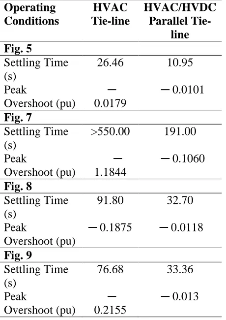
parameter values as shown in Fig. 9. This justifies the robustness of the fuzzy logic controller which is capable to withstand the changes in dynamic parameters of the five unequal area power system. It also depicts the effectiveness of the HVDC link in parallel with existing HVAC tie-line to suppress frequency, tie-line power, and generated power oscillations under various load perturbations in different areas of the system, as also depicted in Table II. From Table II we concluded that settling time, taken in a 5% band and peak overshoots of
the deviation in frequency of area 1 (i.e. ∆f1)
drastically reduced in each different
operating conditions while using HVDC link in parallel with existing HVAC tie-line.
CONCLUSIONS
Int. J. of Engg. Sci. & Mgmt. (IJESM), Vol. 1, Issue 1: Sep. - Dec. 2011, 55-63
thermal reheat turbines with 3%/minute GRC. The system dynamic performance in the wake of load disturbance in different areas of interconnected power system has
been investigated comprehensively by
varying system parameters. It has been observed that responses of the system with parallel HVDC link are better in terms of dynamic parameters such as peak overshoot
and settling time. Simulation results
presented justify the incorporation of HVDC transmission link to supply consumers reliable and quality power.
REFERENCES
[1] C. E. Fosha and O. I. Elgerd, “The
megawatt frequency control problem: a new approach via optimal control theory,” IEEE Transactions on Power
Systems, vol. PAS-89, pp. 563−577,
(1970).
[2] H. Saadat, Power system analysis, Tata
Mc-Graw Hill Publishing Company Limited, New Delhi, India, (2000).
[3] O. I. Elgerd, Electric energy system
theory: An Introduction. Tata Mc-Graw
hill, (1982).
[4] P. Kundur, Power system stability and
control, McGraw-Hill, New York,
(1994).
[5] R. J. Abraham, D. Das, and A. Patra,
“Automatic generation control of
interconnected hydrothermal power
system considering superconducting magnetic energy storage,” International
Journal of Electrical Power and Energy Systems, vol. 29, pp. 571−579, (2007).
[6] S. K. Aditya and D. Das, “Load
frequency control of an interconnected hydro-thermal power system with new area control error considering battery energy storage facility,” International
Journal Energy Research, vol. 24 no. 6,
pp. 525–538, (2000).
[7] M. Mufti, S. A. Lone, S. J. Iqbal, M.
Ahmad, and M. Ismail,
“Super-capacitor based energy storage system for improved load frequency control,”
Electric Power Systems Research, vol.
79, pp. 226–233, (2009).
[8] Ibraheem and P. Kumar, “Study of
dynamic performance of power systems with asynchronous tie-lines considering parameter uncertainties,” Journal of
Institution of Engineers (I), vol. 85, pp.
35−42, (2004).
[9] Ibraheem and P. Kumar, Dynamic
performance enhancement of hydro-power systems with asynchronous
tie-Table II. Comparison between settling time
and peak overshoots under various operating condition for ∆f1
Operating Conditions
HVAC Tie-line
HVAC/HVDC Parallel
Tie-line Fig. 5
Settling Time (s)
26.46 10.95
Peak
Overshoot (pu)
─
0.0179
─ 0.0101
Fig. 7
Settling Time (s)
>550.00 191.00
Peak
Overshoot (pu)
─ 1.1844
─ 0.1060
Fig. 8
Settling Time (s)
91.80 32.70
Peak
Overshoot (pu)
─ 0.1875 ─ 0.0118
Fig. 9
Settling Time (s)
76.68 33.36
Peak
Overshoot (pu)
─
0.2155
Int. J. of Engg. Sci. & Mgmt. (IJESM), Vol. 1, Issue 1: Sep. - Dec. 2011, 55-63
lines,” Journal of Institution of
Engineers (I), vol. 85, pp. 23−34,
(2004).
[10] I. Ngamroo, “A Stabilization of
frequency oscillation in a parallel ac-dc interconnected power system via an HVDC Link,” Science Asia, vol. 28, pp. 173−180, (2002).
[11] R. Thottungal, P. Anbalagan, T.
Mohanaprakash, A. Sureshkumar, and G. V. Prabhu, “Frequency stabilization in multi area system using HVDC link,” in Proceedings of IEEE International
Conference of Industrial Technology,
Mumbai, India, (2006), pp. 590–595.
[12] H. D. Mathur and H. V. Manjunath,
“Study of dynamic performance of thermal units with asynchronous tie-lines using fuzzy based controller,”
Journal of Electrical Systems, vol. 3,
no. 3, pp. 124–130, (2007).
[13] D. M. V. Kumar, “Intelligent controllers
for automatic generation control,” in
Proceedings of IEEE region 10 International Conference on Global connectivity in Energy, Computer, Communication and Control, pp. 557–
574, (1998).
[14] H. D. Mathur and S. Ghosh, “A
Comprehensive analysis of intelligent controllers for load frequency control,” in Proceedings of IEEE Power India
2006 Conference. Delhi. April 10-12.
(2006).
[15] H. D. Mathur and H. V. Manjunath, “A
fuzzy based improved intelligent
controller for automatic generation
control,” International Journal of
Engineering Simulation, vol. 7, no. 3,
pp. 29−35, (2006).
[16] G. A. Chown and R. C. Hartman,
“Design and experience with a fuzzy
logic controller for automatic
generation control,” IEEE Transactions
on power systems, vol. 13, no. 3, pp.
965−970, (1998).
[17] J. Talaq and F. Al-Basri, “Adaptive
fuzzy gain scheduling for load
frequency control, IEEE Transactions
on power systems, vol. 14, no. 1, pp.
145−150, (1999).
[18] C. S. Chang and W. Fu, “Area load
frequency control using fuzzy gain scheduling of pi controllers,” Electrical
Power System Research., vol. 42, pp.
145−152, (1997).
[19] Y. H. Song and A. T. Johns,
“Application of fuzzy logic in power systems: Part 1 General Introduction to fuzzy logic,” IEE power Engineering
Journal, vol. 11, no. 5, pp. 219−222,
(1997).
[20] Y. H. Song and A. T. Johns,
“Application of fuzzy logic in power systems: Part 2 General Introduction to fuzzy logic,” IEE power Engineering
Journal, vol. 12, no. 4, pp. 185−190,
(1998).
[21] IEEE Working Group on Power Plant
Response to Load Changes, “MW response of fossil fuelled steam units,”
IEEE Transactions on Power Apparatus and Systems, vol. PAS-92, no. 2, pp.
455−463, (1973).
[22] IEEE Committee Report, “Dynamic
models steam and hydro turbines in
power system studies,” IEEE
Transactions on Power Apparatus and Systems, Vol. PAS-92(6), pp. 1904−1915, (1973).
[23] Z. A. Zadeh, “Fuzzy sets, information
and control,” vol. 8, pp. 338−353, (1965).
APPENDIX
Nominal parameters of the five area system under investigation:
Pr1 = 2000 MW, Pr2 = 4000 MW, Pr3 = 8000
Int. J. of Engg. Sci. & Mgmt. (IJESM), Vol. 1, Issue 1: Sep. - Dec. 2011, 55-63
R1 = R2 = R3 = R4 = R5 = 2.4 Hz/puMW;
Tg1 = Tg2 = Tg3 = Tg4 = Tg5 = 0.08 seconds;
Tt1 = Tt2 = Tt3 = Tt4 = Tt5 = 0.3 seconds;
Tp1 = Tp2 = Tp3 = Tp4 = Tp5 = 20 seconds;
Kp1 = Kp2 = Kp3 = Kp4 = Kp5 = 120
Hz/puMW;
T12 = T13 = T14 = T15 = T23 = T24 = T25 = T34 =
T35 = T45 = 0.086 puMW/radian;
Tr1 = Tr2 = Tr3 = Tr4 = Tr5 = 10 seconds;
Kr1 = Kr2 = Kr3 = Kr4 = Kr5 = 0.5;
Ptie, 12 = Ptie, 13 = Ptie, 14 = Ptie, 15 = Ptie, 23 = Ptie, 24 = Ptie, 25 = Ptie, 34 = Ptie, 35 = Ptie, 45, (max) =
200 MW;
f = 50 Hz; a12 = a13= a14 = a15 = a23 = a24 =
a25= a34 = a35 = a45 = ─1; Kdc1 = Kdc2 = Kdc3 =
Kdc4 = Kdc4 = 1.0;
Tdc1 = Tdc2= Tdc3= Tdc4= Kdc5 = 0.2 seconds;