SPEED CONTROL OF BRUSHLESS DC
MOTOR ON RESONANT POLE INVERTER
USING FUZZY LOGIC CONTROLLER
* S. Sivakotiah
ASSISTANT PROFESSOR DEPARTMENT OF ELECTRICAL AND ELECTRONICS ENGINEERING, GMR INSTITUTE OF TECHNOLOGY, RAJAM, ANDHRA PRADESH, INDIA-532127
J.Rekha
PG STUDENT, DEPARTMENT OF ELECTRICAL AND ELECTRONICS ENGINEERING GMR INSTITUTE OF TECHNOLOGY, RAJAM, ANDHRA PRADESH, INDIA-532127
Abstract:
Brushless dc motor has been widely used in drive system and servo control because of its fast response ,high density ,high efficiency ,low inertia ,high reliability ,maintenance free. It is however driven by a hard switching frequency, high switching losses, high electromagnetic interference, high acoustic noise and low efficiency. The rectifier/inverter with a simple commutation circuit to provide zero voltage turn on for the switches and soft turn off for diodes. The converter is intended for high performance, medium power applications requiring bidirectional power flow .A new soft switching inverter has been developed to overcome over voltages and over current problems existing resonant link inverter .This inverter employs a single auxiliary switches. The introduces fuzzy logic based soft switching resonant pole inverter using transformer, which can generates dc link voltages notches during chopping which an minimized the drawback of soft switching, The operation principle and control scheme of the inverter are analyzed and performance of the fuzzy controller is compared with conventional PI controller .The simulation result show that the fuzzy controller is compared with the conventional PI controller
Keywords: Brushless Dc Motor, resonant pole inverter, zero voltage switching, zero current switching, fuzzy logic controller
1. Introduction
Fig. 1 Resonant Pole Inverter
The structure of the resonant pole inverter is shown in Fig. 1. Each resonant pole comprises a resonant inductor and a pair of resonant capacitors at each phase leg. These Capacitors are directly connected in parallel to the main inverter switches in order to achieve zero–voltage Switching (ZVS) condition.
The auxiliary resonant commutated pole (ARCP) inverter [6] and the ordinary resonant snubber inverter [7] provide a ZVS condition without increasing the device voltage and Current stress. These inverters are able to achieve real PWM Control. However, they require a stiff dc link capacitor bank .That is center-tapped to accomplish commutation. The center Voltage of dc link is susceptible to drift that may affect the Operation of the resonant circuit. The resonant transition Inverter [8], [9] only uses one auxiliary switch, whose Switching frequency is much higher than that obtained using the main switches. Thus, it will limit the switching frequency of the inverter. A Y-configured resonant snubber inverter [10] has a floating neutral voltage that may cause overvoltage failure of the auxiliary switches. A delta configured resonant snubber inverter [11] avoids the floating neutral voltage and is suitable for multiphase operation without circulating currents between the off-state branch and its corresponding output load. However, the inverter requires three inductors and six auxiliary switches. Hence the inverter cost gets increased and in addition occupies larger space.
Resonant pole inverters have been applied inInduction motor drive applications. They are usually required to change two phase switch states at the same time to obtain a resonant path. It is not suitable for a BDCM drive system as only one switch is needed to change the switching state in a PWM cycle. The switching frequency of three upper switches is different than that of three lower switches in an inverter for a BDCM drive system. All the Switches have the same switching frequency in a conventional inverter for induction motor applications. Therefore, it is necessary to develop a novel topology of soft-switching inverter and special control circuit for BDCM drive systems. This paper proposes a special designed resonant pole inverter that is suitable for BDCM drive systems and is easy to apply in industry. In addition, this inverter possesses the following advantages: low switching power losses, low inductor power losses, low switching noise, and simple control scheme
In this paper, a new fuzzy logic based resonant pole inverter is designed for BLDC motor drive systems which is easy to implement in industries. PI controller has also been implemented for comparison with the proposed fuzzy based control scheme With the development of power electronics technique and Permanent magnet material, permanent magnet brushless DC motor (BLDC) with trapezoidal back electromotive force(BEMF) have been widely used in many applications of variable-speed drives, which have the advantages of higher power/weight and higher efficiency. In the traditional control scheme, the armature winding on the stator of BLDC is commutated electronically by a six-step inverter that switches according to the signals of rotor position. These signals usually can be obtained from Hall Effect sensors. Moreover, the Hall Effect sensors obtain a lower resolution for the rotor angle which can cause torque ripple and degenerate its performance. In order to improve the control performance of BLDC drive
2. Resonant Pole Inverter Topology
Diode Dfp is connected in parallel to the primary winding of the transformer and diode Dr is serially connected with secondary winding across the dc link. There is one snubber Capacitor connected in parallel to each switch of phase leg. The snubber capacitor resonates with the primary winding of the transformer. The emitters of the three auxiliary Switches are connected together. Thus, the gate drive of these auxiliary switches can use one common output dc Power supply in an entire PWM cycle, all the six main switches can be turned off in the ZVS condition as the snubber capacitors (Cra, Crb, Crc) can slow down the voltage rise rate. This enables the turn-off power losses be reduced and the turn-off voltage spike eliminated. Before turning on the main switches, the corresponding auxiliary switch (Sa, Sb, Sc) must be turned on ahead. Main switches get the ZVS condition
Fig. 3Simulation diagram of fuzzy based resonant pole inverter for BLDC motor drive system
3. Controller Design
System is almost eliminated. Fuzzy controller is among the Most suitable choices for system with non-linear Characteristics. Hence, in this work the fuzzy controller is
Used to control the speed of BLDC motor with good dynamic response.
3.1 Proportional Integral Controller Design
The model of PI speed controller is given by,
Where G(S) is the controller transfer function which is torque to error ratio in s-domain, Kp is the proportional gain and Ki is the integral gain. The tuning of these parameters is done using Ziegler Nichols method using the phase and gain Margin specifications. The specifications of the drive application are usually available in terms of percentage overshoot and settling time. The PI parameters are chosen so as to place the poles at appropriate locations to get the desired response.
These parameters are obtained using Ziegler Nichols method which ensures stability. From the dynamic response obtained by simulation, the percentages overshoot Mp and settling time ts which are the measures of Transient behaviors are obtained. The speed loop of the typical BLDC motor under no load condition. The closed loop transfer function of the system is given by
Fig. 4 Speed loop showing the PI controller and BLDC
+(B+Kp/J)s+Ki/J (2)
Where T(S) is the closed loop transfer function and Kp, Ki Are the PI controller parameters, J is the moment of inertia And B is the coefficient of friction.
࣓n J-B (3) ࣓n2 (4)
3.2 Fuzzy Logic Controller Design
Fuzzy logic controller is a rule-based controller. It consists of an input, processing and output stages. The input or fuzzification stage maps sensor or other inputs such as switches, thumbwheels and so on, to the appropriate membership functions and truth values. The processing stage invokes each appropriate rule and generates a result for each, then combines the results of the rules. Finally, the output or defuzzification stage converts the combined result back into a specific control output. The membership function is triangular, although trapezoidal and bell curves are also used, but the shape is generally less important than the number of curves and their placement.
From three to seven curves are generally appropriate to cover the required range of an input value or the “universe of discourse” in fuzzy language. There are several different ways to define the result of a rule, but one of the most common and simplest is the “max – min” inference method, in which the output membership function is given by the truth value generated by the promise. The simulation diagram of fuzzy logic controller
big, negative medium, negative small, zero, controller converges to the reference value, positive small, positive medium and positive big respectively are given in Table. 1.
Fig. 5 Simulation diagram of fuzzy logic controller
For simplicity, membership function is expressed in Exponential form as
(5)
The membership function is an intersection of any two inputs Such as error (e) and change of error (Δe) is written as (6)
Where a, b are defined as an interval of each linguistic Variable, x is the fuzzy input or output variables and i, j Represent the number of labels 1, 6, 7.The triangular shaped membership functions are chosen due to their best control performance and simplicity. The height of the membership functions in this case is one.
An overlap of 50% is provided for neighboring fuzzy subsets. Therefore at any point of the universe of discourse, no more than two fuzzy subsets will have non-zero degree of membership. The inputs to the reference current generator are reference torque (T*) and the rotor position signal (θr). The magnitude of the 3Ф current (I*) is determined by using reference torque (T*). Depending on the rotor position, the reference current generator generates the reference current (ia*, ib*, ic*). These reference currents are fed to the current controller.
4. Simulation Results
frequency of the PWM is 20 kHz. Waveforms of auxiliary switch gate signal (Sb), voltage drop across switch S6 (uS6), transformer primary winding current (iLr) and main switch gate signal (S6) .A BLDC motor with specifications as taken from [15] is shown in Table 2 and is simulated using MATLAB/SIMULINK. The transient response of the motor for both PI and fuzzy controller are presented. The simulation was run for 1 second (simulation time)
4.1 Simulation Results With Fuzzy Controller
Fig. Shows 3Φback Emf,, 3Φcurrents and Electromagnetic torque for the reference speed of 500 rpm.Load torque is applied at 0.1 seconds. The 3Φ trapezoidal back Emf and currents are almost with 120º phase difference. The speed response shows that the settling time of the motor with fuzzy controller is about 0.2 seconds and overshoot is almost eliminated with fuzzy controller. The speed of the PMBLDC motor, when controlled with the
.Fig. 6 (a) 3Φ back EMF (b) 3Φ currents
(c) Electromagnetic torque and
Fig. 7 FLC vs. PI speed response for PMBLDC motor
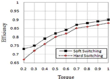
From the results obtained, it can be seen that the resonant pole inverter works well under various load currents. Due to soft switching condition, the switching power losses are low. The efficiency Vs torque curves of hard switching and soft switching under rated speed are shown in Fig. 8 and it is observed that efficiency is improved with the soft switching inverter..
Fig. 8 Efficiency Vs torque curves
5. Conclusion
Appendix
Table 2 The Parameters of BLDC Motor
Parameters Value
DC Link Voltage Base Speed
Armature Resistance Armature Inductance Magnetic Flux Linkage No of Poles
Moment of Inertia Friction Coefficient
Vdc
ωb Ra La Ø P J B
300V 1000 rpm 2.875 Ω 8.5 mH 0.175 Wb 4
0.89 m2 0.005 Nm - s
References
[1] M. Dehmlow, K. Heumann, and R. Sommer .Resonant Inverter Systems for Drive Applications. EPE J., vol. 2, no. 4, pp. 225–232, 1992.
[2] D. M. Divan. The Resonant DC Link Converter – A New Concept in Static Power Conversion. IEEE Trans.Ind. Applicat, vol.25, no.2, pp. 317– 325, 1989
[3] D. M. Divan, and G. Skibinski. Zero–Switching Loss Inverters for High Power Applications. IEEE Trans.Ind. Appl., vol. 25, no. 4, pp. 634– 643, 1989.
[4] L. Malesani, P. Tenti, P. Tomasin, and V.Toigo.High Efficiency Quasi resonant DC Link Three-Phase Power Inverter for Full-Range PWM. IEEE Trans.Ind. Appl., vol. 31, no. 1, pp. 141–148, 1995.
[5] Y. C. Jung,, H. L. Liu, G.C. Cho, and G. H. Cho. Soft Switching Space Vector PWM Three-PhasePower Inverter for Full-Range PWM. IEEE
Trans.Ind. Appl., vol. 31, no. 1, pp.Inverter using A New Quasi parallel Resonant DC Link. Proc. IEEE Power Electronics Specialists Conf.,