Modeling and Simulation of Series
Compensator to Mitigate Power Quality
Problems
S.Sadaiappan1
M.E., Student, Thiagarajar College of Engineering, Thiruparakundram, Madurai, Tamil Nadu, India
[email protected] http://www.tce.edu
Dr.P.Renuga2
Associate Professor, EEE Department, Thiagarajar College of Engineering, Thiruparakundram, Madurai, Tamil Nadu, India
[email protected] http://www.tce.edu
D.Kavitha3
Lecturer, Thiagarajar College of Engineering, Thiruparakundram, Madurai, Tamil Nadu, India
[email protected] http://www.tce.edu Abstract:
Power Electronics and Advanced Control technologies have made it possible to mitigate power quality problems and maintain the operation of sensitive loads. Among power system disturbances, voltage sags, swells and harmonics are some of the severe problems to the sensitive loads. The series compensation method is best suited to protect such loads against those disturbances. The use of a series compensator (SC) to improve power quality is an isolated power system is investigated. The role of the compensator is not only to mitigate the effects of voltage sag, but also to reduce the harmonic distortion due to the presence of non linear loads in the network. In this paper, a series compensator is proposed and a method of harmonic compensation is described and a method to mitigate voltage sag is investigated. The proposed series compensator consists of Energy Storage System (ESS) and Voltage Source Inverter (VSI), Injection Transformer. The ESS can be a capacitor of suitable capacity. ESS would act as a buffer and generally provides the energy needed for load ride-through during voltage sag. Injection Transformer is used to inject the voltage in transmission line in appropriate level. In this way the terminal voltage of the protected sensitive load can be regulated to maintain a constant level. The modeling and simulation of the proposed series compensator was implemented in Matlab Simulink work space. Simulation results showed that the proposed series compensator was efficient in mitigating voltage sags and harmonics and thus improve the power quality of the isolated power system. This approach is different from conventional methods and provides effective solution. If this method is enhanced in future it could provide much more improved power quality.
Keywords: Power Quality Problems; Series Compensator; ESS; VSI; Harmonics; Voltage Sag; MATLAB.
1. Introduction
Isolated power systems are commonly found in rural and remote areas of the world. Isolated power systems are characterized by limiting generating capacity. The sensitive loads which are present in the isolated power systems are much more affected by the power quality problems. Power Electronics and Advanced Control technologies have made it possible to mitigate power quality problems and maintain the operation of sensitive loads. Power quality problems encompass a wide range of disturbances such as voltage sags/swells, flickers, harmonics distortion, impulse transient, and interruptions.
Among power system disturbances, voltage sags, swells and harmonics are some of the severe problems to the sensitive loads, because (i) the occurrence of voltage sag in the system can cause devices/process down time,
1
S.SADAIAPPAN, M.E., Student, Thiagarajar College of Engineering, Thiruparakundram, Madurai, Tamil Nadu, India.
effect on product quality, failure/malfunction of equipments etc., (ii) the occurrence of harmonics in the system can cause excessive losses and heating in motors, capacitors and transformers connected to the system. To avoid those undesirable affects the proposed method mitigates the problems caused by voltage sag and harmonics.
This paper analyses the key issues in the power quality problems, In the proposed system Voltage sag occurs due to the three phase fault in the transmission line and harmonics occurs due to the connection of controlled six pulse converter (rectifier) to the main drive load(non linear load). All these factors affect the sensitive load which is connected in parallel to the main drive load. So the proposed system protects the sensitive load by mitigating the voltage sags and harmonics using series compensation technique.
2. Main Sources, Causes and Effects of Electrical Power Quality Problems:
Power Quality is “Any power problem manifested in voltage, current, or frequency deviations that results in failure or misoperation of customer equipments”[1]. Power systems, ideally, should provide their customers with an uninterrupted flow of energy at smooth sinusoidal voltage at the contracted magnitude level and frequency. However, in practice, power systems, especially the isolated systems, some of the primary source of distortion [2] can be identified as below.
Non – Linear Loads
Power Electronic Devices
IT and Office Equipments
Arcing Devices
Load Switching
Large Motor Starting
Larger capacitor bank energies
Embedded Generation
Electromagnetic radiations and Cables
Storm and Environment Related Causes
While power disturbances occur on all electrical systems, the sensitivity of today’s sophisticated electronic devices makes them more susceptible to the quality of power supply. For some sensitive devices, a momentary disturbance can cause scrambled data, interrupted communications, a frozen mouse, system crashes and equipment failure etc. A power voltage spike can damage valuable components. Power quality encompass a wide range of disturbances such as voltage sags/swells, flicker, harmonics distortion, impulse transient, and interruptions.
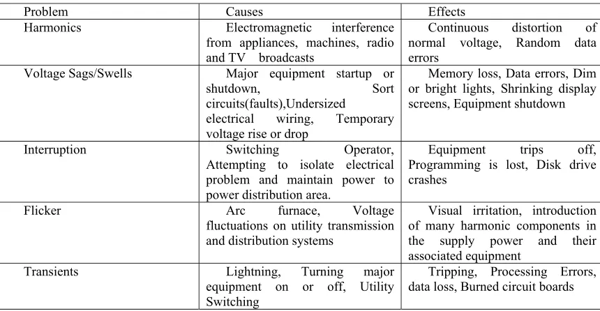
The Common Power quality issues and their causes and effects are summarized [2] in the table below. Table 1. Causes and Effects of Common Power Quality Issues
Problem Causes Effects
Harmonics Electromagnetic interference
from appliances, machines, radio and TV broadcasts
Continuous distortion of normal voltage, Random data errors
Voltage Sags/Swells Major equipment startup or
shutdown, Sort circuits(faults),Undersized
electrical wiring, Temporary voltage rise or drop
Memory loss, Data errors, Dim or bright lights, Shrinking display screens, Equipment shutdown
Interruption Switching Operator,
Attempting to isolate electrical problem and maintain power to power distribution area.
Equipment trips off, Programming is lost, Disk drive crashes
Flicker Arc furnace, Voltage
fluctuations on utility transmission and distribution systems
Visual irritation, introduction of many harmonic components in the supply power and their associated equipment
3. Methods to Improve Power Quality issues
A traditional method to achieve improve power quality is to use passive filters connected at the sensitive load terminals. However, this practice has some shortcomings: the effectiveness of the scheme could deteriorate as the source impedance or load condition changes; it can lead to resonance between the filter and the source impedance. Essentially an active filter, connected at the sensitive load terminal, injects harmonic currents of the same magnitude but of opposite polarity to cancel the harmonics present there. However harmonics distortions are only part of the problem, the variations in the drive load would result in voltage sag [3] . Thus, the challenge is to regulate the sensitive load terminal voltage so that its magnitude remains constant and any harmonic distortion and voltage sags are reduced to an acceptable level. This paper introduces series compensator and its operating principle. Then a simple control based PWM method is used to compensate Harmonics, Voltage sags. At the end MATLAB SIMULINK model based simulated results were presented to validate the effectiveness of the proposed control method of Series Compensation.
4. Modeling of Series compensator
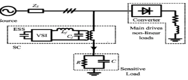
Figure 1. The basic structure of Series Compensator.
The simple power system model shown in Figure 1 is used to explain the principle of the proposed mitigation method[4]. The upstream generators are aggregated and represented as an ideal voltage source. Zs
represents the equivalent source impedance. The main drives or machinery loads are modeled as a lumped resistive-inductive load connected to the source through a power converter, assumed to be a six-pulse rectifier. The much smaller capacity sensitive loads are assumed to be supplied through point of common coupling and are modeled by the resistor R in parallel with the capacitor C. The SC is connected upstream from the sensitive load through an injection transformer. It is series connected with the sensitive load. The function of the SC is to ensure that the voltage across the sensitive load terminals is of high quality. The central part of the SC is an energy storage system (ESS) and a VSI where a PWM switching scheme is often used[5]. The ESS can be a capacitor of suitable capacity. Because of the switching, harmonics are generated, and filtering is required. The function of each component of Series Compensator is as follows,
Energy Storage System
ESS would act as a buffer and generally provides the energy needed for load ride-through during voltage sag. In this way the terminal voltage of the protected sensitive load can be regulated to maintain a constant level.
Voltage Source Inverter
Capacitor
Series compensator has a large DC capacitor to ensure constant input supply to inverter.
Filter
Filters are used to convert the PWM inverted pulse waveform into a sinusoidal waveform. This is achieved by removing the unnecessary higher order harmonic components generated during the DC to AC conversion in the Voltage Source Inverter (VSI), higher orders harmonic components distort the compensated output voltage.
Voltage Injection Transformer
In a three phase system, three single-phase transformer units or one three phase transformer unit can be used for voltage injection purpose. In the proposed system Voltage sag occurs due to the three phase fault in the transmission line and harmonics occurs due to the connection of controlled six pulse converter (rectifier) to the main drive load (non linear load). So the proposed system mitigates the voltage sags and harmonics.
By-Pass Switch
If the voltage sags appear in the power system, By-pass switch is used to protect the inverter from high currents. When the event of a fault or a short circuit on downstream, the Series Compensator changes in to the bypass condition where the VSI inverter is protected against over current flowing through the power semi conductor devices.
5. Control Philosophy Used in Series Compensator
The harmonics is generated in the load terminals using six pulse converter with fixed firing angle is connected to the main drive non linear load which is parallel to the sensitive load. Voltage sag is created at load terminals via a three phase fault. The above voltage problems are sensed separately and passed through the sequence analyzer. The magnitude component is compared with reference voltage (Vref). Pulse width Modulation (PWM) control technique [6] is applied for inverter switching so as to produce a three phase 50 Hz sinusoidal voltage at the load terminals. Chopping frequency is in the range of few KHz. The IGBT inverter is controlled with PI controller in order to maintain 1 per unit voltage at the load terminals. PI controller (Proportional Integral Controller) is a closed loop controller which drives the plant to be controlled with a weighted sum of the error (difference between the output and the desired set point) and the integral of that value. One advantage of a proportional plus integral controller is that the integral term in a PI controller causes the steady-state error to be zero for a step input. PI controller input is an actuating signal which is the difference between the Vref and Vin. Output of the controller block is of the form of δ.
Output of comparator = Vref – Vin ………(1) Where (1p.u. =Base Voltage)
Vref equal to 1 p.u. voltage
Vin voltage in p.u. at the load terminals. The angle δ is provided to the PWM signal generator to obtain desired firing sequence.
Figure 2. Indirect PI Controller Vin
PI Controller Vref
Output of PI Controller Actuating Signal
+
The sinusoidal signal Vcontrol is phase-modulated by means of the angle δ. In this way the angle δ is produced in three phases.
i.e., VR = Sin (ωt + δ) ………(2)
VY = Sin (ωt + δ + 2π/3) ……… (3)
VB = Sin (ωt + δ + 4π/3) ……… (4)
6. Illustration of the Series Compensator Test System
Electrical circuit model of Series compensator Test system is shown in figure1. It is used to verify the effectiveness of the Series Compensator. The simulations were accomplished using Matlab simulink.
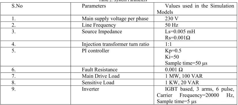
Table 2. System Parameters
S.No Parameters Values used in the Simulation
Models
1. Main supply voltage per phase 230 V
2. Line Frequency 50 Hz
3. Source Impedance Ls=0.005 mH
Rs=0.001Ω
4. Injection transformer turn ratio 1:1
5. PI controller Kp=0.5
Ki=50
Sample time=50 µs
6. Fault Resistance 0.001 Ω
7. Main Drive Load 1 MW, 100 VAR
8. Sensitive Load 1 KW, 20 VAR
9. Inverter IGBT based, 3 arms, 6 pulse,
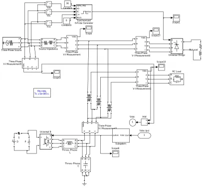
7. Simulation Results and Discussions 1 Vabc Discrete, Ts = 5e-005 s.
v + -Vca v + -Vbc v + -Vab g A B C + -Universal Bridge g A B C + -Universal B A B C
T hree-Phase Source
Va
bc
A B C
a b c
T hree-Phase V-I Measurement5 Vabc A B C a b c T hree-Phase V-I Measurement4 Va bc
A B C a b c
T hree-Phase V-I Measurement3 Vabc A B C a b c T hree-Phase V-I Measurement1 Vabc A B C a b c T hree-Phase V-I Measurement
A B C A B C Three-Phase C A B C A B C Three-Phase L alpha_deg AB BC CA Block pulses Synchronized 6-Pulse Generator Vabc (pu) pulses Subsystem A B C A B C Source Impedance Scope6 Scope3 Scope17 Scope10 Scope1 Scope S A B C RC Load P 1 2 1 2 1 2 D 0 Constant1 30 Constant Add RL Load 1 Vabc (pu)
Figure 3.Simulink model
Harmonics issues
In simulink model figure 3 shows the harmonics is generated in the transmission line using six pulse converter connected to the main drive non linear load which is parallel to the sensitive load. The percentage of total harmonic distortion in the sensitive load side is, in phase1 13.65%, in phase2 16.51%, in phase3 19.12%
.
The simulation results carried out without series compensator, the harmonics generated are 3, 5, 7, 9, 11, 13, 17th harmonics in all there phases. The harmonics distortions produced in all the three phases is shown using
FFT analysis in figure4, which is also described in table3.
0 0.1 0.2 0.3 0.4 0.5 0.6 0.7 0.8 0.9 1
-1.5 -1 -0.5 0 0.5 1 1.5
Time in Sec
(a) (b)
(c) (d)
The simulation results carried out with series compensator, generated harmonics are reduced. The reduced harmonics distortions in all the three phases is shown using FFT analysis in figure5, which is also described in table4.
0 0.1 0.2 0.3 0.4 0.5 0.6 0.7 0.8 0.9 1
-1 -0.8 -0.6 -0.4 -0.2 0 0.2 0.4 0.6 0.8 1
Time in Sec
(a) (b)
(c) (d)
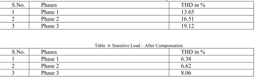
The following tables show the simulation result carried out with and without using series compensator in mitigating harmonics.
Table 3. Sensitive Load – Before Compensation
S.No. Phases THD in %
1 Phase 1 13.65
2 Phase 2 16.51
3 Phase 3 19.12
Table 4. Sensitive Load – After Compensation
S.No. Phases THD in %
1 Phase 1 6.38
2 Phase 2 6.62
3 Phase 3 8.06
A thyristor based six pulse converter used in this system is a power electronic device (fast switching device) adds harmonics in the system voltage and increases the total harmonics distortion of the system. The tables 3 and 4 show simulation results carried out with and without using series compensator respectively.
When the system simulation is carried on without series compensator the harmonics are generated at load point of all three phases. This harmonics affects the sensitive load. Then the series compensator is brought in to service for harmonic mitigation, the sensitive load is protected against the distortion introduced by the main drive load and the total harmonic distortion is reduced up to 50% as shown in table 3 and 4. This approach helps to mitigate harmonics better when compared to other traditional methods [4].
Voltage Sags Issues
In simulink model when the fault is introduced at the point of common coupling, sag appears at the period 0.4 to 0.6 secs in all the three phases is shown in figure 6(a). When the series compensator is connected to the system the appeared sag is mitigated is shown in figure 6(b).
0 0.1 0.2 0.3 0.4 0.5 0.6 0.7 0.8 0.9 1
-1 -0.8 -0.6 -0.4 -0.2 0 0.2 0.4 0.6 0.8 1
Time in Sec
0 0.1 0.2 0.3 0.4 0.5 0.6 0.7 0.8 0.9 1
-1 -0.5 0 0.5 1 1.5
Time in Sec
(a) (b) Figure 6. (a) Three phase voltage sag (b) Sag mitigation
The table 5 shows the appearance of the sags and its mitigation results Table 5. Matab Simulink Results for Voltage Sags Problem Without
compensation With compensation
Sag Nominal Voltage
Reduced upto 75% (from 0.4 to 0.6 sec)
8. Conclusion
Voltage quality improvement in an isolated power system through series compensation has been investigated. The power system contains significant proportion of fluctuating nonlinear load and a high level of harmonic distortions is observed. The SC is also designed to maintain the fundamental frequency component of the terminal voltage of protected sensitive load. In this paper, a complete simulated series compensator system has been developed by using Matlab Simulink software. It is shown that the simulated SC developed works successfully to improve power quality. PWM technique is used to control the injection voltage of the SC so that it can mitigate the effects of the harmonics and voltage sag has been proposed.
The proposed system performs better than the traditional methods in mitigating harmonics and voltage sags. The proposed SC can handle both balanced and unbalanced situations without any difficulties and would inject the appropriate voltage component to correct rapidly and anomaly in the supply voltage to keep the load voltage balanced and constant at the nominal value
9. References
[1] Roger C. Dugan, Mark f. Mcgranaghan, Dr. Surya Santoso and H. Wayne Beaty., “Electrical power systems quality”, Tata McGraw Hills publications, 2002.
[2] Devaraju.T, Dr.Veera Reedy.V.C and Dr.Vijayakumar.M, “Modeling and simulation of customer power devices to mitigate power quality problems” International Journal of Science and Technology, Vol. 2(6), 2010, pp.1880-1885.
[3] Wang.T.X, Choi S.S. and E.K.K. Sng “Series compensation method to mitigate harmonics and voltage sags and swells” IET Gener. Transm. Distrib., Vol. 1, No. 1, January 2007,pp.96-103.
[4] Choi, S.S., Wang, T.X., and Sng, E.K.: “Power quality enhancement in an isolated power system through series compensation’. Proceedings of 15th Power System Computation Conference, Liege, Belgium, August 2005,Section 22, pp.1-7
[5] Wang.T.X. and Choi S. S.,” Enhancement of Voltage Quality in Isolated Power Systems” IEEE Transactions on power delivery, Vol. 22, No. 2, April 2007.
[6] Leela.S, Dash. S.S., “Control of Three Level Inverter Based Dynamic Voltage Restorer” Journal of Theoretical and Applied Information Technology, Vol.8, No. 1, 2009. pp-13-17.
[7] Rosli Omar, Nasrudin Abd Rahim, Marizan Sulaiman” Modeling and Simulation for Voltage Sags/ Swells Mitigation using Dynamic Voltage Restorer (DVR)” Journal of Theoretical and Applied Information Technology, Vol.5, No. 4, 2009, pp-464-470.