EXPERIMENTAL & NUMERICAL
STUDY OF NATURAL CONVECTION IN
ENGINE BLOCK
PRATIMA S. PATIL1
Department of Mechanical Engineering, JSPM’s Rajarshi Shahu College of Engineering, Tathawade, Pune-33, India.
[email protected] DR. SACHIN L. BORSE2
Department of Mechanical Engineering, JSPM’s Rajarshi Shahu College of Engineering Tathawade, Pune-33, India.
[email protected] Abstract:
Experiments were conducted to study natural convection in three different engine blocks. Current study uses three engine blocks machined from plain Aluminium. Plain Cylinder Block, Cylinder Block with fins & Square Block with fins is used. Inside the cylinder block fine heaters were fitted to mimic heating at different locations. Temperatures at various locations were measured. Few experimental data is compared with CFD results by Fluent.
Keywords: Engine heat transfer; Natural Convection. 1. Introduction
Heat transfer to the cylinder walls of internal combustion engines is recognized as one of the most important factors that influences both engine design and operation. Research efforts concerning heat transfer in internal combustion engines often target the investigation of thermal loading at critical combustion chamber components. In-cylinder heat transfer is a significant feature of internal combustion engines (ICEs) which affects engine performance and emissions. Measurements of heat transfer have been performed and models have been produced by a large number of researchers. The accuracy of predicting the wall heat transfer is required not only to calculate the heat transfer rate from the gas pressure and temperature data, but also necessary for the internal combustion engines to improve the overall engine simulation. The heat transfer process from the gases to the coolant through the combustion chamber wall has in general the three heat transfer elements. From the gases to the combustion chamber wall the heat is transferred mainly by convection with a contribution from radiation. The heat flux is conducted through the combustion chamber walls and then convected from the walls to the coolant.
The peak burned gas temperature in the cylinder of an internal combustion engine is of order 2500ºC. Maximum metal temperatures for the inside of the combustion chamber space are limited to much lower values by a number of considerations. These conditions lead to heat fluxes to the chamber walls that can reach as high as 10 MW/m2 during the combustion period. However, during other parts of the operating cycle, the heat flux is essentially zero. The flux varies substantially with location; moving high-temperature burned gases generally experience the highest fluxes. In regions of high heat flux, thermal stresses must be kept below levels that would cause fatigue cracking (so temperatures must be less than about 400ºC for cast iron and 300ºC for aluminum alloys). The gas-side surface of the cylinder wall must be kept below about 180ºC to prevent deterioration of the lubricating oil film. Spark plug and valves must be kept cool to avoid knock and preignition problems, which result from overheated spark plug electrodes or exhaust valves. Solving these engine heat-transfer problems is obviously a major design task. Heat transfer affects engine performance, efficiency and emissions. For a given mass of fuel within the cylinder, higher heat transfer to the combustion chamber walls will lower the average combustion gas temperature and pressure.
Conduction
Conduction heat transfer is energy transport due to molecular motion & interaction. Conduction heat transfer through solids is due to molecular vibration. Fourier determined that Q/A, the heat transfer per unit area (W/m2) is proportional to the temperature gradient dT/dx. The constant of proportionality is called the material thermal conductivity k.
Fouriers equation
The thermal conductivity k depends on the material, for example, the various materials used in engines have the following thermal conductivities (W/mK):
The thermal conductivity also depends somewhat on the temperature of the material. Convection
Convection heat transfer ids energy transport due to bulk fluid motion. Convection heat transfer through gases & liquids from solid boundary results from the fluid motion along the surface.
Newton determined that the heat transfer/area, Q/A, is proportional to the fluid solid temperature difference Ts -Tf. The temperature difference usually occurs across a thin layer of fluid adjaicent to the solid surface. This thin fluid layer is called boundary layer. The constant of proportionality is called the heat transfer coefficient, h. Newton’s Equation:
Radiation
Radiation heat transfer is energy transport due to emission of electromagnetic waves or photons from a surface or volume. The radiation does not require a heat transfer medium, & can occurs in a vacuum. The heat transfer by radiation is proportional to the fourth power of absolute material temperature. The proportionality constant is the Stefan-Boltzmann constant equal to 5.67 × 10⁻⁸ W/m2K4. The radiation heat transfer also depends on the material properties represented by , the emissivity of the material.
Cylinder heat flux & Temperatures-
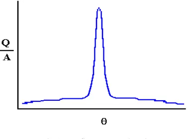
The surface temperature of the cylinder can be measured with thermocouples, & the resulting cylinder heat flux deducted from Fourier’s conduction equation & the unsteady heat conduction equation. The figure below is a representative graph of the cylinder heat flux as a function of crank angle.
Fig. 1: Heat flux versus crank angle
The heat flux begins rising when the combustion flame impacts cylinder wall, has a maximum at peak cylinder pressure when gas temperatures peak, typically 20º after TDC. The peak heat fluxes are on the order of 1 to 3 MW/m2. The heat flux increases with increasing load & speed. As the cylinder wall temperature increases, the piston & ring friction will be reduced, decreasing the fuel consumption, the heat flux to the wall from the combustion gases will decrease, & the formulation of pollutants such as nitrous oxides also increases.
temperatures around the combustion chamber can exceed 1000° F. In order to prevent the overheating of the engine oil, cylinder walls, pistons, valves, and other components by these extreme temperatures, it is necessary to effectively dispose of the heat. It has been stated that a typical average-sized vehicle can generate enough heat to keep a 5-room house comfortably warm during zero degree weather .Approximately 1/3 of the heat in combustion is converted into power to drive the vehicle and its accessories. Another 1/3 of the heat is carried off into the atmosphere through the exhaust system (conduction, convection & radiation). The remaining 1/3 must be removed from the engine by the cooling system.
In this project experiments were conducted to study natural convection in three different engine blocks. Current study uses three engine blocks machined from plain Aluminium. Plain Cylinder Block, Cylinder Block with fins & Square Block with fins is used. Inside the cylinder block fine heaters were fitted to mimic heating at different locations. Temperatures at various locations were measured. Few experimental data is compared with CFD results by Fluent.
1.2 Problem Definition 1.2.1 Purpose/Need
1. To study unsteady heat transfer in engine block with different position of piston under natural convection condition.
1.2.2Aim and Objectives of Project The main objectives of this project are:
1. To develop & improve understanding in engine heat transfer under natural convection. Study aimed at creating unsteady heat conduction in the engine block subjected to heat flow according to different position of piston.
Total heat applied was 127 Watts. Same heat was applied to cylinder block with different piston positions by splitting the heat into different patches.
2. Create experimental data to use by CFD community for validation purpose. 3. To compare experimental data with CFD results.
2. Experimental Work
2.1 Experimental Set-up of Engine Blocks
Experiments were conducted for natural convection of three engine blocks. These three engine blocks were manufactured from Aluminium. Plain Cylinder block, Cylinder block with fins & Square block with fins. Inside the cylinder block fine heaters were fitted to mimic heating at different locations. Temperatures at various locations were measured. In this way heating & cooling trend was observed. This data can be further used by CFD for the purpose of validation.
Fig. 2: Plain Cylinder, Cylinder with fins & Square block with fins
Table 1 Specifications of Engine
Sr. No. Part list Specifications
1 Length 100 mm
2 Bore 64 mm
3 Displacement volume 322 c.c.
4 Cylinder Block material Aluminium
5 Cylinder Design Plain Cylinder, Cylinder with fins
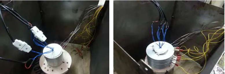
Fig. 3: Overall view of plain cylindrical engine block set-up Fig..4: Overall view of cylinder with fins engine block set-up
Fig. 5: Overall view of square with fins engine block set-up Fig. 6: Block Diagram
2.2 Methodology
Three tests were conducted on plain cylinder, cylinder with fins & square block with fins. These three engine blocks were manufactured from Aluminium. Inside the cylinder block fine heaters were fitted to mimic heating at different locations as shown in figure. Then keeping input energy constant, variation in temperature recorded on data logger. In this 1 to 5 coils were operated sequentially up to respective steady state of temperatures obtained.
Table 2
Operating parameter & test conditions
1st heater ON 2nd heater ON 3rd heater ON 4th heater ON 5th heater ON Q 127 watt 63.5 watt 42.33 watt 31.75 watt 25.4 watt Q
0 63.5
watt 42.33 watt 31.75 watt 25.4 watt Q
0 0 42.33
watt 31.75 watt 25.4 watt Q
0 0 0 31.75
watt
25.4 watt Q
0 0 0 0 25.4
watt
2.2.1 Natural Convection
3. Numerical Work 3.1 Introduction
Computational Fluid Dynamics (CFD) provides a qualitative (and sometimes even quantitative) prediction of fluid flows by means of
• Mathematical modeling (partial differential equations) • Numerical methods (discretization and solution techniques) • Software tools (solvers, pre- and post-processing utilities)
CFD enables to perform ‘numerical experiments’ (i.e. computer simulations) in a ‘virtual flow laboratory’. Experiments were conducted for natural convection of three engine blocks. Inside the cylinder block fine heaters were fitted to mimic heating at different locations.
3.2 CFD Model Preparation & Specifications 1. Circular Engine without fins
Total Mesh: 622381 cells,
Mesh size for Engine Block : 443866, Mesh Size for Fluid Domain: 178515.
The air surrounding the engine is taken as Incompressible Ideal gas. The air flow is laminar in Natural convection.
Boundary condition:
Natural convection : Inlet -Pressure Inlet , Outlet- Pressure outlet (1 atm)
2. Circular Engine with fins Total Mesh: 8394296 cells,
Mesh size for Engine Block : 562237, Mesh Size for Fluid Domain: 356943. 3. Square Engine Block
Total Mesh: 1510970 cells,
Mesh size for Engine Block: 738291, Mesh Size for Fluid Domain: 772679.
The air surrounding the engine is taken as Incompressible Ideal gas. The air flow is laminar in Natural convection.
Boundary condition:
Natural convection : Inlet -Pressure Inlet, Outlet- Pressure outlet (1 atm)
Heater is modeled by solid ring and internal heat generation is applied to solid ring such that net heat generated by ring is 127 W.
4. Results & Discussions
4.1Measurements of temperature were taken at 6 various locations & trend (Time vs temperature) observed. In this temperature is increased till steady state obtained & then switched off the heaters & block allows to cool naturally & observed the trend. From this observation we can conclude that temperature near the inner side of cylinder block is higher ( i.e. Location 1-L1) & temperature near the outer side of cylinder block is less (i.e. Location 6-L6).For Observation table refer Appendix II
Graph 1: Cylinder Block without fins
4.2 Measurements were taken at 12 locations and Time versus Temperature graphs is plotted.
In this initially temperature increased till steady state obtains & then cooling trend observed. In this graph temperature near the inner side of cylinder block is higher ( i.e. Location 1-L1) & temperature near the outer side of cylinder block is less (i.e. Location 6-L6),similarly L7 is near to the inner side of cylinder block & L12 is near the outer side of cylinder block.
Graph 2: Cylinder Block with fins
Graph 3: Square Block with fins
4.4.In this experimental data is compared with CFD (fluent) data. Around 20% variation found in circular block without fin & with fins & around 10% variation found in square block with fins. Refer Appendix III
0 20 40 60 80 100 120 140 160 180
0 1000 2000 3000 4000 5000 6000 7000 8000 9000
Te m p e rat u re [C ]
Time [s]
Time
‐
Temperature
Temperature Fluent [ C ]
Graph 4: Comparison of Experimental & CFD result (Circular Block without Fins Natural Convection)
0 20 40 60 80 100 120 140 0 48 0 96 0 14 40 19 20 24 00 28 80 33 60 38 40 43 20 48 00 52 20 55 20 60 00 64 80 69 60 74 40 79 20 84 00 88 80 93 60 98 40 103 20 108 00 Te m p e rat u re (i n C)
Time (in Sec.)
Fluent[C] Experimental…
0 20 40 60 80 100 120
0 1000 2000 3000 4000 5000 6000 7000 8000 9000
Te
m
p
.[
C
]
Time[Sec]
Experimental [C] Fluent Temp [C]
Graph 6. Comparison of Experimental & CFD result (Square Block with Fins Natural Convection)
4.5.In this graph temperature of location 1 of three blocks (Plain cylinder, Cylinder with fins & Square block with fins) is compared.From this graph we can conclude that heat transfer rate is faster in Square block with fins than Plain cylinder & Cylinder with fins.
Graph 7 Comparison of Heating and cooling Trends of Three Blocks of location P1 (Experimental)
5. Conclusions
[1] Temperature gradient is existing in blocks with fins & no temperature gradient exists in block without fins. [2] Maximum heat transfer rate occurs in with fins block as compared to plain block ( without fins)
[3] Comparison of the experimental data of heat conduction with numerical work data was performed & around 10-20% variation found.
[4] Unsteady state heat transfer analysis of cylinder engine blocks was done using 3D CFD software and compared it using experimental data. The computed values correspond to the experimental data.
[5] Temperature gradient for square block is more than circular without fin and circular block with fin. Heat transfer rate is more in square block with fin as compared to circular without fin and circular block with fin. References
[1] Yuh-Yih Wu, Bo-Chiuan Chen, Cheng-Ting Ke, Feng-Chi Hsieh, Hua-Chuang, 2009, "Heat transfer model for small-scale spark-ignition engines," International Journal of Heat and Mass Transfer, 52: pp. 1875–1886.
[2] Paulius V. Puzinauskas, Gary Hutcherson, Bryan D. Willson, 2003, "Ignition and boost effects on large-bore engine in-cylinder heat transfer," Applied Thermal Engineering,23: pp. 1–16.
[3] Michael A. Marr, James S. Wallace1, LarryPershin, Sanjeev Chandra and Javad Mostaghimi, 2010, "Preliminary Testing of Metal-Based Thermal Barrier Coating in a Spark-Ignition Engine," Journal of Engineering for Gas Turbines and Power Vol. 132 /072806-1. [4] Kukwon Cho, Ronald O. Grover, Jr., Dennis Assanis, Zoran Filipi, Gerald Szekely, Paul Najt and Rod Rask, 2010, "Combining
Instantaneous Temperature Measurements and CFD for Analysis of Fuel Impingement on the DISI Engine Piston Top, Journal of Engineering for Gas Turbines and Power, Vol. 132 / 072805-1.
[5] Octavio Armas, Jose Rodriguez, Francisco Payri, Jaime Martin,John R. Agudelo, 2005, "Effect of the trapped mass & its composition on the heat transfer in the compression cycle of a reciprocating engine,” Journal of Applied Thermal Engineering 25: pp. 2842-2853 [6] John B.L Heywood, 1988. Internal Combustion Engine, Mc-Graw Hill, 2 nd
ed., pp. 235-488.
[7] Willard W. Pulkrabek, 1994, Engineering Fundamentals of the Internal Combustion Engine, Pearson Prentice, 2nd
[8] V. Ganeshan, 2007, Internal Combustion Engines, Tata Mc-Graw Hill, 4th
ed., pp. 524-946. [9] R. Stone,1999, Introduction to internal combustion engines, Palgrave, New York,3rd
ed.,pp-281-293. [10] R. K. Rajput, 2006, Heat & Mass Transfer, S. Chand publication, 3rd
ed., pp. 495-527. [11] J. P. Holman, 2007, Experimental Methods for Engineers, Tata Mc-Graw Hill, 7th