* To whom all correspondence should be addressed.
Simulation of Heat Transfer and Fluid Dynamics Processes in
Shell-and-Pipe Heat Exchange Devices with Segmental and
Helix Baffles in a Casing
Rinat Shaukatovich Misbakhov1, Victor Mihaylovich Gureev2,
Nikolai Ivanovich Moskalenko1, Andrey Mihaylovich Ermakov2
and Ilyas Zul’fatovich Bagautdinov1
1Kazan State Power Engineering University, Russia, 420066, Kazan, Krasnoselskaya st., 51. 2Kazan National Research Technical University named After A.N. Tupolev,
Russia, 420111, Kazan, Marx st., 10. doi: http://dx.doi.org/10.13005/bbra/2234 (Received: 09 June 2015; accepted: 26 July 2015)
Increase of heat exchange in shell-and-pipe heat exchange devices allows to decrease cost, dimensions and weight of heat exchange equipment. The main directions in a field of increase of heat exchange are application of surface intensifiers on pipes of a heat exchange devices, in a case there is a need to increase heat exchange of a heat transfer agent inside pipes, and application of various types of baffles, in a case there is a need to increase casing heat exchange. The paper presents the results of the study of increase of heat exchange in a casing by means of segmental and helix baffles; circular baffles were not taken into account, because in that case mechanism of increase of heat exchange is the same with segmental baffles and has the same disadvantages, such as dead zones before and after the baffles. In the study we developed solid state models of heat exchanging devices with segmental and helix baffles created finite-element models, carried out numerical studies of heat exchange and fluid dynamics processes in shell-and-pipe heat exchange devices with segmental and spiral inserted baffles at various flow conditions of a heat transfer agent. Also, values of coefficients of heat transfer, heat flow, flow structure and pressure losses in pipes and casing at various flow conditions are obtained. Application of baffles allows to increase heat flow for a whole range of flow conditions. The biggest effect in absolute values of heat flow is achieved by means of implementation of helix baffles, however, it also leads to the biggest values of hydraulic losses. The main advantage of helix baffles is uniform distribution of a heat transfer agent in a casing and absence of dead zones, which are formed in a case of segmental baffles.
Key words: Intensifier, Heat transfer, Simulation, Heat exchange, Flow structure.
Nowadays, one of the most expensive energy resources is heat energy. Its high cost is caused by both the problems its production (low efficiency heat generating equipment, increased cost of fuel, significant production expenses), and problems of its effective transfer and use. Heat energy from a moment of production to a moment of consumption is transfered several times in heat
exchanging devices (HED) and heat exchanging elements, which thermal efficiency coefficients often do not exceed 40-70%.
In the energy sector of Russia shell-and-pipe HED are still the most used type of that kind of devices. At that, that kind of HED belong to smooth pipe type, which have significant dimensions, high degree of dirt adherence and short service life of a pipe bank. Moreover, increasing capacity of various energy equipment causes significant thermal and dynamic loads.
increase of thermal and hydraulic efficiency can be successfully solved by means of application of heat exchange intensifiers. Heat exchange intensifiers, which allow to significantly increase thermal output with moderate or comparable increase of hydraulic resistance are of the greatest interest. Surface intensifiers of heat exchange belong to that type. They constitute a significant class, which consists of the following elements: helix and wire inserts and knurls of various configurations, micro ribs, spherical, cylindrical, conical and other protrusions and notches, chevron stamped surfaces etc. The main feature of intensifiers is that they impact boundary layer, which causes the largest thermal resistance n heat transfer, and destroy it with further increase of turbulence of flow in a wall layer. Influence on only a wall layer doesn’t lead to significant increase of hydraulic resistance. Increase of heat exchange in channels of heat exchanging equipment during flow of liquid and gaseous heat transfer agents is up to 2.5 times with a comparable increase of hydraulic pressure. An example of application of a surface intensification in heat exchanging equipment is GOST 27590-88 “Water heaters for heat supply systems. General specifications”, where it is demonstrated that application of profile pipes in HED allows to increase thermal efficiency of heat exchanger and its thermal capacity in 1.35 times with the same dimensions or to decrease length of a heat exchanger for the same value, while maintaining the same thermal efficiency. Transfer to the next form factor by casing diameter in a case of use of profile pipes allows to decrease length of heater in 2 times.
The feature of surface intensifiers is the fact that due to increase turbulence and vortex formation at a wall zone dirtying of a surface is decreasing. That fact increases attractiveness of that kind of intensifiers.
The desire to further decrease weight and dimensions of heat exchangers resulted in wider use of plate heat exchangers. This class of heat exchangers allows to disassembly casing and heat exchange matrix for periodic manual and mechanical cleaning, it also has small equivalent diameters of channels for heat transfer agents and, therefore, their higher velocities and increased heat transfer coefficients. Use of chevron and stamped plates as heat exchanging surfaces also increase surface
of heat exchange and increases turbulence of a flow. However, there is a limitation – plate heat exchanges are not designed for significant pressure, which are frequently used in power engineering and the major part of modern industrial processes.
In that regard, development of HED meeting modern requirements of energy efficiency, technological effectiveness and operational characteristics becomes an important problem.
All existing and prospective power energy equipment, as well as renewable energy equipment, heat exchanging equipment amounts for a significant part in terms of dimensions, metal consumption and functions; in many aspects it determines future technical and economical parameter of equipment. Nowadays and in future, one of main, technically and economically the most affordable and reasonable ways to increase the cost-effectiveness of energy equipment is improvement of heat-exchange equipment, which can be achieved by means of application of effective methods for intensification of heat exchange.
From the point of view of flow in single-phase heat exchangers used methods are increase of roughness at a surface and increase of surface by means of ribs or notches, twisting of a flow by means of spiral ribs, auger devices, vortex devices, which are installed at a channel entrance, mixing of gas bubbles into a flow of a liquid and solid particles or liquid drops into a flow of a gas, rotation or vibration of a heat exchanging surface, pulsation of a flow of a heat transfer agent, application of electrostatic fields to affect a flow, pumping out of a flow from a wall layer and stream systems. Efficiency of those methods varies, but, generally, increase of heat transfer reaches 2-3 times, at that, for various methods of intensification energy consumption significantly differ and seriously depend on flow conditions.
hydraulic resistance depending on flow conditions. Important operation factors of HED for a long time were durability, technological efficiency and general efficiency. The main criteria for competitiveness in HED market is a manufacturer’s reputation. Customers are ready to work with manufacturers that are able to provide technical quality and speed of execution of an order. The major part of customers will be willing to order equipment from manufacturers, which can provide additional services in a form of design, cost estimation and installation. Finally, another key criterion for the selection of a supplier is price. All manufacturers should follow a flexible pricing strategy and ensure that they offer a heat exchangers at prices based on assessment of a whole market. They should guarantee that they offer competitive outside price for a market environment and growing presence of suppliers from other regions of the world. In addition, ease of maintenance, absence of additional works for cleaning of heat exchange surfaces and durability start to play the very important role.
In the energy sector dirtying and cleaning equipment is a topical problem. Existing technologies for cleaning are inseparably connected with the additional labor expenditures and additional expenditures of fuel and chemicals, as well as with environment issues. Experiment results demonstrated that turbulent flow of water with increased hardness along outer and inner surface of pipes with knurled protrusions, deposition of salts is reduced in 3-5 times as compared with a smooth pipe. In a pipe with protrusions dirt deposits evenly spaced to an original surface, and heat exchange intensification effect remains in a dirtied pipe as well and may even increase. Probably, it is possible to operate heat exchangers with intensifiers without cleaning during a whole service life, because thickness of dirt in a pipe with protrusions after a certain period of time almost stabilizes at an acceptable level. It is clear that the mentioned property of pipes with protrusions is an additional argument in favor of their use in industry.
The main disadvantage of shell-and-pipe HED as compared with plate HED is difference in flow conditions, heat transfer and heat exchange, which exists inside pipes and inside a casing. In a casing due to geometrical restrictions for bank of
pipes flow conditions with lesser velocities take place, as compared to a case inside of pipes, which results in a decrease of heat transfer and thermal capacity of a devices in a whole. One of the methods for an increase of heat transfer in a casing is use of special baffles. The presented paper discusses segmental and helix baffles, which allow to re-distribute flows in a casing.
Disadvantages of a plate heat exchanger are requirements for purity of heat transfer agents (i.e., they are used with chemically purified water), high cost of components (cost of fillers, which are replaced over a period of time, can exceed 50% of a heat exchanger’s cost; during operations fillers are worn off, crack or shrivel, also they are damaged during cleaning of a hear exchanger), requirement for cleaning with special liquids (often expensive) for removal of deposits (in utility heat supply it is recommended to use only dismountable heat exchangers), poor repair ability (for example, in a case of replacement of a damaged plate due to corrosion it is necessary to completely disassemble a heat exchanger, in a case of a shell-and-pipe heat exchangers, damaged pipes are just sealed).
METHODOLOGY
Nowadays, there are two generally used methods for study of intensification of a heat exchange, which complement each other. The first methods is the full-scale test at experimental installations, which are equipped with instruments, and the second is the numerical simulation of processes of heat and mass transfer and fluid dynamics by means of specialized software. The main advantage of the numerical simulation is possibility to understand a structure of a flow, as well as to visualize fields of coefficients of heat transfer, pressure and temperature, which is necessary for modernization and optimization of structure of heat exchange equipment.
In the presented study for numerical simulation we used ANSYS CFX software (certificate No. ANS2011-S015).
mm, length – 500 mm. Heat transfer agent’s flow scheme – counter-flow. Working medium – water-to-water. Range of changes of flows for both internal and internal circuit of heat transfer agents is 0.1 – 0.7 kg/s with step of 0.1 kg/s. Temperature of cold heat transfer agent in pipes – 8°C. Temperature of hot heat transfer agent in casing – 95°C.
Finite-element model of HED consists of three calculation domains. The total number of nodes is 4.69 mln.
For generation of calculation mesh tetrahedral elements, which allow to achieve the most accurate description of a complex geometry of HED and which are recommended for solution of that kind of problems in CFX software. Minimal size of an element of finite-element mesh was 0.06 mm, maximum – 3 mm, which allows to take into account feature of flow of a heat transfer agent along helix and segmental baffles. For SST turbulence model in Ansys CFX 15 prismatic sublayers were used for simulation of laminar sublayer at a pipe’s surface (Fig. 1).
In practice, HED most frequently use turbulent flow conditions of a heat transfer agent, therefore, for solution of the problem we selected SST (Shear Stress Transport) model of turbulence,
which allows to obtain the most accurate solutions of that kind of engineering problems1.
RESULTS
First, calculations were carried out for HED with smooth pipes without baffles.
Flow structure in the casing is presented in Fig. 2.
Fig. 2 shows that the flow presses towards the upper part of the casing of HED, which means incomplete and ineffective use of the heat exchanging surface.
Nowadays, there are many methods for increase of a thermal transfer in heat exchanging equipment. In the presented study we discuss increase of a heat transfer directly in a casing, because exactly in a casing velocity has the least absolute value.
Main method for increase of heat transfer in a casing is use of baffles, which turn flow. Traditional way is use of a segment baffles. Fig. 3 shows flow structure in HED obtained by means of the numerical simulation.
The main disadvantage of segmental baffles are dead ends behind them, which have low velocity and strong twisting of flow, which leads to formation of deposits during operation, a
Fig. 1. Finite-element model of HED. Fig. 2. Flow lines in the casing in the heat exchanger without baffles.
Fig. 3. Lines of flow in a heat exchanger with segmental baffles.
heat exchanging surface in that places becomes covered and heat exchange is decreasing, which, in turn, decreases thermal capacity of the whole HED. Experimental and theoretical studies on helix baffles were carried out in works2-16; the novelty of
the presented study is a special geometry of baffles, which allow to increase heat flow with minimum hydraulic resistance, moreover, helix baffles of “Helix” type are implemented and practically used by “ABB Lummus HT BV” company and Research center “Tehnohim” Inc., that baffles create continuous helix flow with practically ideal displacement in a casing, which allows to design heat exchanging equipment with unchanging efficiency during the whole service life due to cleanness of a heat exchanging surface. That engineering solution was tested on hundreds of existing devices, and it is supported by tens of certificates of recognition and patents. In any point of a system flow velocity has a specified value, which excludes deposition of suspension particles and various resinous deposits in a casing of Lotus type heat exchangers. Combination with high velocity of media in pipes allows to obtain intensive
heat exchange during a whole service life of HED 17-19. Flow structure in HED with helix baffles is
presented in Fig. 4.
Distribution of flow lines in a casing shows uniform flow along a pipe bank, absence of dead zones, and, moreover, simulation allowed to detect increased speed in the flow’s core. Moreover, the zone of the flow’s concentration, passing along the external edge of a helix baffle, also exists. For more detailed analysis of heat exchange processes let’s discuss fields of heat transfer coefficient on an external surface of pipes and baffles in a casing.
Surface heat transfer coefficients in a casing, presented in Fig. 5a-c demonstrate presence of dead zones in a case of application of segmental baffles and uniform distribution of heat transfer coefficient along a whole surface in a case of application of helix baffles, which allows to take more thermal energy from HED of the same size. Relationship between heat flow value of HED and flow conditions of a heat transfer agent is presented in Fig. 6.
Fig. 5. Heat transfer coefficient at an external surface of a pipe bank. a – segmental baffles, b – helix baffles.
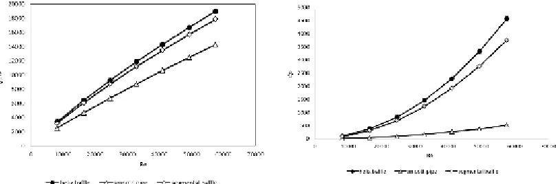
Fig. 6. Relationship between heat flow and flow conditions of HED.
Calculations of HED were carried out for the same dimensions, velocity in HED was changing from 0.2 to 2.5 m/s, Re value – from 3000 to 50000 and mass flow – from 0.1 to 0.7 kg/s.
Use of baffles allows to increase heat flow by 27% in a case of use of segmental baffles and by 36% in a case of use of helix baffles for all studied flow conditions.
Hydraulic resistance in HED was also discussed, the results are presented in Fig. 7.
Analysis of graphs shows increase of hydraulic resistance in a casing for a case of segmental baffles in 7 times and for a case of helix baffles in 8.5 times for a whole range of flow conditions. Moreover, the calculation with increased step of segmental baffles (Fig. 5c) was carried out, as a result, increase of a heat flow as compared with a regular number of turn in 1.6% and increase of hydraulic resistance in 10%.
For identification of optimal mode of thermal efficiency, depending on flow condition, the following equation was used (3):
) Re ( )
(Q Q0 = f ...(3)
where
Q: heat flow of a heat exchanger with baffles, W; Q0: heat flow of a heat exchanger without baffles, W.
Fig. 8 shows relationship between relative thermal efficiency and Re value, which decreases with increase of Re. It is related with the fact that with more developed turbulent flow conditions smooth pipes start to work more efficiently, and baffles increase hydraulic resistance of a casing.
CONCLUSION
Use of helix baffles allows to increase heat flow up to 37%, but it is recommended to use them Fig. 8. Thermal efficiency depending of flow conditions.
flow conditions with low turbulence (Re 15000-25000) in order to reduce hydraulic pressure, moreover, use of spiral inserts allows to obtain uniform distribution of flow along cross-section of a casing.
The study was carried out in a framework of a state research and development contract No. 2014/448 (project code 2806). The results of the study can be used for development of high performance HED in energy sector and automobile industry [20, 21].
REFERENCES
1. (n.d.). Retrieved July 15, 2015, from http:// w w w . c f d o n l i n e . c o m / W i k i / S S T _ k -omega_model.
2. Zou, J., Yuan, F., & Hu, L. Analyses on effect of helix angle on the continuous helical baffles heat exchanger. Advanced Materials Research, 2014; 1008-1009: 901-905.
3. Zhang, L., Xia, Y., & Jiang, B. Experimental study of large-shell-diameter heat exchangers with small-helix-angles non-continuous helical baffles. Advanced Materials Research, 2012; 468-471, 1789-1793.
4. Wang, W.-H., Chen, Y.-P., Wu, J.-F., Cao, R.-B., & Dong, C. Numerical simulation of flow field and temperature field in shell side of trisection helix heat exchangers. Kung Cheng Je Wu Li Hsueh Pao. Journal of Engineering Thermophysics, 2012;1(33): 131-134. 5. Cao, R., Qian, C., Sun, H., Zhang, Z., Zhao, F.,
Yang, K., & Wang, F. Experimental study of shell-side heat transfer and pressure drop in a helix baffle heat exchanger. Beijing Huagong Daxue Xuebao (Ziran Kexueban). Journal of Beijing University of Chemical Technology (Natural Science Edition), 2011;5(38), 111-115. 6. Chen, Y.-P., Wang, W.-H., Li, Y.-Q., Liu, H.-J., Zhou, B., & Cao, R.-B. Study on heat transfer performance at shell-side of trisection baffled helix heat exchangers. Kung Cheng Je Wu Li Hsueh Pao. Journal of Engineering Thermophysics, 2010;11(31): 1905-1908. 7. Zhao, Z., Mi, H., Cheng, H., & Feng, W.
9. Tasouji, A., Khalilarya, S., & Jafarmadar, S. Tube bundle replacement for segmental and helical shell and tube heat exchangers: Experimental test and economic analysis. Applied Thermal Engineering, 2014;2(62), 622-632.
10. Wu, J.-Q., Zhu, D.-F., & Wang, H. Impact of baffle space height on the helical baffle double-pipe heat exchanger. Guocheng Gongcheng Xuebao. The Chinese Journal of Process Engineering, 2013; 2(14), 204-210.
11. Azar, R., Khalilarya, S., & Jafarmadar, S. Tube bundle replacement for segmental and helical shell and tube heat exchangers: Experimental test and economic analysis. Applied Thermal Engineering, 2014;2(61), 622-632.
12. Zhang, J., Tao, W., & He, Y. Field synergy angle distribution and local heat transfer characteristic in shell and tube heat exchanger with helical baffles. Huagong Xuebao. CIESC Journal, 2013; 8(64), 2769-2773.
13. Cao, X., Du, W.-J., & Cheng, L. Performance of heat exchanger with novel overlapped helical baffles. Kung Cheng Je Wu Li Hsueh Pao. Journal of Engineering Thermophysics, 2013; 6(34), 1130-1132.
14. Cao, X., Du, W., & Cheng, L. Analyses on flow and heat transfer performance and entropy generation of heat exchanger with continuous helical baffles. Huagong Xuebao. CIESC Journal, 2012; 8(63), 2375-2382.
15. Zhang, L., Xia, Y., & Jiang, B. Experimental study of large-shell-diameter heat exchangers with
small-helix-angles non-continuous helical baffles. Advanced Materials Research, 2012; 468-471, 1789-1793.
16. Cao, X., Du, W., Ji, S., & Cheng, L. Influence of overlap size on shell-side performance of heat exchangers with helical baffles. Zhongguo Dianji Gongcheng Xuebao. Proceedings of the Chinese Society of Electrical Engineering, 2012; 8(32), 78-84.
17. (n.d.). Website of “Lotus” engineering company. Retrieved July 15, 2015, from http://lîtus1.ru/ teplîîbmenniki-zàkàzñhikàm/pîñhemu-lîtus-intensiven/115.
18. (n.d.). Website of “Tehnohim” company. Retrieved July 15, 2015, from http:// îld.teñhnîhim.ñîm/ñàtàlîg/28/16/.
19. (n.d.). Website of “RAN GRUPP” company. Retrieved July 15, 2015, from http:// rangroup.ru/areas/mathsim/performed/hdhe/. 20. Gureev, V., Sosnovsky, A., Yunusov, R., Gureev,
R., Salahov, R. Modernization of production version of oil cooler for “KAMAZ” engine. Bulletin of Kazan national research technical university named after A.N. Tupolev, 2012;3: 41-45.