Efficient Interleaver Design for MIMO-OFDM
based Communication System on FPGA
1
Girish Kumar N G,
2Draveena R Mote,
3Manjushree S,
4Srilakshmi S,
5Shibani D
1,2,3,4,5Dept. of Telecommunication Engineering, BIT, Bengaluru, India
Abstract
In this paper, we exhibit a memory-proficient and speedier Interleaver usage method for MIMO-OFDM communication systems on FPGA. The IEEE 802.16 standard is utilized as a source of perspective for conducting execution and examination. A strategy for the Interleaver design on FPGA and its memory use results are exhibited. Our design uses the base required on-chip memory for the Interleaver execution. Utilizing the proposed Interleaver design strategy, the information rates for MIMO-OFDM based communication systems are multiplied for 2×2 MIMO systems without utilizing the transmit diversity.
Keywords
Convolution Encoder, MIMO, OFDM, FPGA, Interleaver, QAM
I. Introduction
The IEEE 802.16 characterizes the standard for broadband wireless access covering the physical layer and medium access particulars for Wireless Metropolitan Area Networks (WMAN). The IEEE 802.16 Air Interface Standard is an innovation that is assuming a key part in altered broadband wireless MAN [1-2]. The Forward Error Correction (FEC) component in the standard assumes an essential part in its execution. A number of strategies are being utilized to accomplish exceedingly powerful error-control coding, for example, convolution codes and concatenated codes. However, Interleaver design becomes a major part in the FEC instrument. The point of interleaving is to reorder the approaching information and make the neighboring bits non-contiguous by a component, to adapt to the burst errors happening throughout the transmission of information over the channel. Memory usage and frequent memory utilization to time are a critical piece of Interleaver design, focusing on less memory use and decreased memory access with a specific end goal to decrease the power dissemination of the overall system. A memory-efficient Interleaver design strategy has been proposed in [3], where the creator exhibits a separated memory bank design for the execution of Interleaver for IEEE 802.16e. An efficient memory address control strategy that can enhance the execution Interleaver is proposed in [3], yet no points of interest are given. An examination of the impacts of interleaving procedure on otherworldly effectiveness of IEEE 802.16 for various situations is done in [4]. They likewise measured the framework throughput and Interleaver square defers, and proposed answers for Interleaver design. In[5], the creators explore auxiliary conduct of Interleaving parameters and propose a few streamlining techniques for the convolution code (CC) Interleaver of IEEE 802.16 standard. In this paper, we introduce an efficient Interleaver design for IEEE 802.16 system on FPGA. This paper concentrates on the Interleaver design of the system actualized in [5]. Our objective is to accomplish least memory use, quicker interleaving, and expanded velocity of the general system. We utilize the interleaving technique characterized in the standard and present an efficient FPGA execution of the proposed design.
II. System Discription
The fundamental OFDM correspondence framework’s physical
layer is as shown in fig. 1. The Forward Error Correction (FEC) pieces incorporate convolution encoding, puncturing, and interleaving. An adjustment of the framework portrayed in Figure 1 is to utilize two separate information streams to upgrade the information rate and conceivably build the quantity of receiving antennas by utilizing spatial and transmit diversity qualities. however, in this examination, just spatial assorted qualities are utilized by having two parallel information streams that make up a 2×2 MIMO-OFDM correspondence framework.
Fig. 1: Block Diagram of OFDM based Communication System
A. Convolution Encoding
Convolution codes are normally specified by the following parameters:
n=number of output bits k=number of input bits
m=number of memory registers
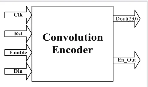
Convolution
Encoder
Clk
Rst
Enable
Din
Dout(2:0)
En_Out
Fig. 2: Convolution Encoder
The efficiency of the convolution codes is measured by the ratio k/n. commonly k and n parameters range from 1 to 8 and m from 2 to 10, and the code rate from 1/8 to 7/8, for the applications like deep space communication code rate is as low as 1/100.
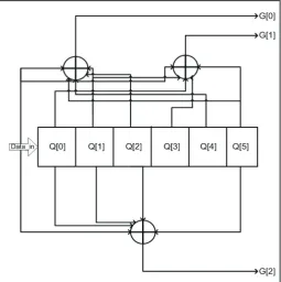
Fig. 3: 1/3 Non-Recursive, Non-Systematic Convolution Encoder With Constraint Length 5
The fig. 3 shown above is with a rate 1/3(k/n) encoder with a constraint length k=5, the generator polynomials are g1= [ 011011], g2=[110101] and g3=[111001]. Therefore the output bits are calculated by the following equations:
G[0]=Din+Q1+Q2+Q4+Q5 (1) G[1]=Din+Q0+Q1+Q3+Q5 (2) G[2]=Din+ Q0+Q1+Q2+Q5 (3)
B. Puncturing
In coding theory, puncturing is the procedure of expelling a percentage of the parity bits in the wake of encoding with an error-correction code. This has the same impact as encoding with an error-correction code with a higher rate, or less excess. However, with puncturing the same decoder can be utilized paying little heed to what number of bits have been punctured, in this way puncturing extensively builds the adaptability of the framework without fundamentally expanding its many-sided quality. At times, a pre-characterized example of puncturing is utilized as a part of an encoder. At that point, the converse operation, known as DE puncturing, is executed by the decoder. Puncturing is utilized as a part of UMTS during the rate coordinating procedure. It is likewise utilized as a part of Wi-Fi, GPRS and EDGE, and also in the DVB-T and DRM Standards. Puncturing is regularly utilized with the Viterbi algorithms as a part of coding frameworks. During Radio Resource Control (RRC) Connection set methodology, during sending NBAP radio connection setup message the uplink puncturing utmost will send to NODE B, alongside U/L spreading component and U/L scrambling code.
Punctured codes are represented as follows:
For rate 1/n parent encoder the puncturing pattern can be represent as ‘nxp’ matrix p whose elements are 1’s and 0’s with ‘1’ indicating inclusion and ‘0’ indicating deletion.
Example: Given encoder generator polynomial. G= [1+D2, 1+D+D2]
And punctured matrix as
It indicates that within two encoded blocks, the first bit of second encoded block is eliminated.
C. Interleaving
Interleavers and De-interleavers are composed and utilized as a part of the setting of qualities of the errors that may happen when the message bits are transmitted through an uproarious channel. To comprehend the elements of an interleavers/deinterleaver, comprehension of mistake attributes is crucial. Two sorts of errors are concern for communication framework outline engineer. They are burst error and random errors
1. Random Errors
Error locations are autonomous of one another. errors on one area won’t influence the errors on different areas. Channels that present these sorts of errors are called channels without memory (since the channel has no learning of blunder areas since the mistake on area does not influence the lapse on another area).
2. Burst Errors
Errors are relied on upon one another. Case in point, in channels with profound blurring attributes, errors frequently happen in bursts (influencing continuous bits). That is, slip in one area has an infectious impact on different bits. As a rule, these errors are thought to be reliant and such channels are thought to be channels with memory.
A standout amongst the most famous approaches to right burst errors is to take a code that functions admirably on random errors and interleave the bursts to “spread out” the errors with the goal that they seem random to the decoder. There are two sorts of interleavers normally being used today, block interleavers and convolution interleavers.
The block Interleaver is stacked line by line with L codeword’s, each of length n bits. These L codeword’s are then transmitted section by segment until the Interleaver is exhausted. At that point the Interleaver is stacked again and the cycle rehashes. At the recipient, the codeword’s are de-interleaved before they are decoded. A burst of length L bits or less will bring about close to 1 bit mistake in any one codeword. The random blunder decoder is a great deal more prone to right this single slip than the whole burst. The Parameter L is known as the Interleaver degree, or Interleaver profundity. The Interleaver profundity is picked taking into account most pessimistic scenario channel conditions. It must be sufficiently huge so that the interleaved code can deal with the longest slip bursts expected on the channel. The principle disadvantage of block interleavers is the deferral presented with every column by-line fill of the Interleaver.
new audience by presenting long stops between speaker moves. Indeed, even short postpones of under one second are adequate to disturb typical discussion. Another hindrance of interleavers is that a keen jammer can pick the proper time to stick to bring about most extreme harm. This issue is overcome by randomizing the request in which the Interleaver is exhausted.
Practically speaking, interleaving is one of the best burst error revising procedures. In principle, it is the most exceedingly awful approach to handle burst errors. Why? From a strict probabilistic sense, we are changing over “great” errors into “terrible” errors. Burst errors have structure and that structure can be abused. Interleavers “randomize” the errors and decimate the structure. Hypothesis varies from reality, however. Interleaving may be the main procedure accessible to handle burst errors effectively.
Viterbi [7] demonstrated that, for a channel weakened by a heartbeat jammer, abusing the burst structure is insufficient. Interleaving is still needed. This does not imply that we ought to be imprudent about our decision of code and bring up the slack with long interleavers. Codes intended to right burst errors can accomplish the same execution with much shorter interleavers. Until the coding scholars find a superior way, interleaving will be a key mistake control coding procedure for burst channels.
III. System Implementation
The IEEE 802.16 (WiMAX) framework is executed on FPGA for outline imitating and confirmation. Convolutional encoder and puncturing squares are actualized utilizing shift registers and XOR doors. For QPSK, 16-QAM, and 64-QAM mapping, puncturing lessens the code rate to 3/4 as portrayed in[8]. There is no puncturing utilized for BPSK mapping as the code rate is dependably rate 1/2. The Interleaver is actualized utilizing RAM obstructs as a part of the FPGA and utilizing Logic Cells (LC) for the state machine of the location generator for perused/compose operations.
Twofold buffering method is utilized to actualize the Interleaver to take out the postponement in the interleaving process. After the main piece of images is put away in the cradle, the address generator [9-12] begins creating read addresses and begins perusing information from the cushion. Meanwhile, the second buffer is loaded with approaching information and the Interleaver will begin perusing from the second buffer after the first is perused out totally. Table 1 demonstrates the buffer sizes for diverse interleaving plans utilized as a part of our framework. The number of supports increment with the expansion in tweak image size, with the goal that we can compose/read information from them at the same time.
A. Matrix Interleaver design
In the proposed design we have considered a matrix of size 10 X 5.This matrix will have 50 locations to store data. All the locations of the temporary matrix are first initialized to 0’s.Then the punctured 3 bit data are first stored in a temporary matrix of the same size of 10*5 in each cycle of the clock and after 50 clock cycles the data is shifted to the Interleaver matrix similar in size to the temporary matrix.
Each location in the 10 X 5 matrix stores 3 bit punctured data. The write operation to the Interleaver takes place row wise and the read operation takes place column wise. Thus the interleaving operation is achieved.
B. 16 QAM Modulation
The 3 bit outputs which are read column wise from the Interleaver matrix are appended with a single 0 bit at the LSB. Now the 4 bit data obtained is sent to the 16 QAM modulator which gives 16 bit real and 16 bit imaginary outputs which are mapped using the constellation mapping as shown below.
Fig. 5: Constellation Diagram for 16 QAM
IV. Hardware Utilization
Table 1: RAM Resource Utilization for the 16 QAM Modulation Scheme
Mapping Type 16-QAM [2] 16-QAM(Our Design) Value Percentage Value Percentage Slices out of 5472 1094 19.99% 264 4.82% 4 Input LUTs out of
10944 1323 12.08% 217 1.982% slice Flip flops out of
10944 1275 11.65% 350 3.198% Maximum Frequency
(MHz) 92.520 333.36
We have considered a reference paper titled “Design and Implementation of an area efficient Interleaver for MIMO-OFDM systems” published in the International Journal of Engineering Trends and Technology (IJETT) – Vol. 4 Issue 7- July 2013 for reference and to compare our results.
The comparison parameter considered is the Area of the Interleaver.
For 16QAM,
The total number of slices available is 5472 of which our •
design utilizes 264 and the design implemented in the reference paper uses 1094.
The percentage improvement is 15.17%.
The total number of 4 input LUT’s available is 10944 of •
which our design utilizes 217 and the reference design utilizes 1323.
The percentage improvement is 10.098%.
The number of slice flip flops available is 10944 of which our •
The percentage improvement is 8.452%.
The maximum operating frequency for our design is 333.36 MHz and 92.52MHz for the reference design. •
Fig. 6: Interleaver Simulation Result
Fig. 7: Final Output Simulation Result
The above fig. shows the simulation results and the following parameters where considered.
Code rate=1/3 Clk= global clock Rst =reset
en1, en2=enable signals
din1,din2= inputs to transmitter1 (Tx1), transmitter2 (Tx2) Rcr_out 1, Rcr_out2 = outputs of receiver1 (Rx1), receiver2 (Rx2)
If rst =1, no output obtained; •
If en=0,no output obtained; •
din1, din2 are 1bit inputs given to Tx1 and Tx2 •
respectively.
These inputs undergo processing while the move through the •
entire communication system.
The outputs, Rcr_out 1, Rcr_out2 obtained after processing •
undergo OFDM communication.
Outputs Rcr_out 1, Rcr_out2 follow the inputs din1, din2 •
with a delay of 2.455ms.
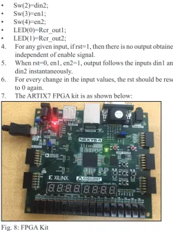
A. FPGA Kit results
FPGA kit used is ARTIX 7. 1.
The pins on the FPGA kit are configured using the standard 2.
configurations.
The inputs are configured as switches and the outputs are 3.
configured as LED’s. Sw(0)=rst;
•
Sw(1)=din1; •
Sw(2)=din2; •
Sw(3)=en1; •
Sw(4)=en2; •
LED(0)=Rcr_out1; •
LED(1)=Rcr_out2; •
4. For any given input, if rst=1, then there is no output obtained independent of enable signal.
5. When rst=0, en1, en2=1, output follows the inputs din1 and din2 instantaneously.
6. For every change in the input values, the rst should be reset to 0 again.
7. The ARTIX7 FPGA kit is as shown below:
V. Conclusion
In this paper, an efficient way to design the IEEE 802.16 standard transmitter on FPGA is exhibited. An uncommon configuration technique is utilized to execute the Interleaver with least memory prerequisite and beginning dormancy. This methodology can likewise be utilized to outline other rapid correspondence frameworks or to enhance their pace. The proposed improvements could be used in real time applications since they just require supplanting the current interleaving parameters and don’t include any equipment adjustment. The transmitter utilizing distinctive adjustment plans have been coded and animated and contrasts and regard to region, recurrence and force uses.
References
[1] IEEE Standard for Local and Metropolitan Area Networks – Part 16: Air Interface for Broadband Wireless Access Systems, IEEE Std. 802.16-2009
[2] Y. Houand and T. Hase, “New flexible OFDM structure for consumerelectronics communication systems,” IEEE Trans. Consumer Electron., Vol. 55, No. 1, pp. 191–198, Feb. 2009.
[3] H. Yu, M.-S. Kim, E. young Choi, T. Jeon, and S. Kyu Lee, “Design andprototype development of MIMO-OFDM for next generation wirelessLAN,” IEEE Trans. Consumer Electron., Vol. 51, No. 4, pp. 1134–1142, Nov. 2005. [4] J. Soler-Garrido, D. Milford, M. Sandell, and H.
Vetter,“Implementation and evaluation of a high-performance MIMO detectorfor wireless LAN systems,” IEEE Trans. Consumer Electron., Vol. 57, No. 4, pp. 1519 –1527, Nov. 2011.
[5] C.-S. Choi, Y. Shoji, and H. Ogawa, “Implementation of an OFDMbaseband with adaptive modulations to grouped subcarriers for millimeter-wave wireless indoor networks,” IEEE Trans. ConsumerElectron., Vol. 57, No. 4, pp. 1541– 1549, Nov. 2011.
[6] S. L. Shieh, “Concatenated BCH and LDPC Coding Scheme with Iterative Decoding Algorithm for Flash Memory”, IEEE communications letters, Vol. 19, Issue 3, 2015, pp. 327-330
[7] S. Lin, D. J. Costello, “Error Control Coding”, 2nd ed. Englewood Cliffs, NJ, USA: Prentice-Hall, 2004.
[8] Z. Iqbal, S. Nooshabadi, “Effects of Channel Coding and Interleavingin MIMO-OFDM Systems,” In 54th IEEE International Midwest Symposiumon Circuits and Systems (MWSCAS), Seoul, Korea, Aug. 2011.
[9] S. Haene, D. Perels, A. Burg,“A real-time 4-stream MIMO-OFDM transceiver: System design, FPGA implementation, andcharacterization,” IEEE J. on Sel. Areas in Commun., Vol. 26, No. 6, pp. 877–889, Aug. 2008.
[10] L. Boher, R. Rabineau, M. Helard,“FPGA implementation of and iterative receiver for MIMO-OFDM systems,” IEEE J. on Sel. Areas inCommun, Vol. 26, No. 6, pp. 857–866, Aug. 2008.
[11] J.-M. Lin, H.-Y. Yu, Y.-J. Wu, H.-P. Ma,“A power efficient baseb and engine for multiuser mobile MIMO-OFDMA communications,” IEEE Trans. Cir. and Sys. I: Regular Papers, Vol. 57, No. 7, pp. 1779 –1792, July 2010.
[12] Y.-N. Chang,“A low-cost dual-mode deinterleaver design,” IEEE Trans. Consumer Electron., Vol. 54, No. 2, pp. 326– 332, May 2008.
GIRISH KUMAR N G Currently working as Assistant Professor, Department of Telecommunication Engineering, Bangalore Institute of Technology, Visvesvaraya Technological University, Karnataka, India. He has more than 7.5 years of teaching experience in Electronics and Communication Engineering. He Received the B.E. degree in Electronics and Communication Engineering from Visvesvaraya Technological University, Karnataka, India in the year 2005. Received the Master of Science Degree in Intelligent Systems in School Of Computing, from University of Sunderland, United Kingdom in the year 2007 and Received M.Sc (Engg) by Research, with specialization in Electronics and Communication in RRC, Visvesvaraya Technological University, Belagavi, Karnataka, India in the year 2015.
Draveena R Mote, Currently pursuing Bachelor of Engineering in Telecommunication Engineering, Bangalore Institute of Technology, completed Internship in Bharat Heavy Electricals Ltd on Basic Projects on PLC hardware design software.
Manjushree S, Currently pursuing Final Year Bachelor of Engineering in Telecommunication Engineering, Bangalore Institute of Technology. Have great Interest to pursue research in the field of Image processing, Error control Coding.
Srilakshmi S, Currently pursuing Final Year Bachelor of Engineering in Telecommunication Engineering, Bangalore Institute of Technology. Have great Interest to pursue research in the field of Image processing, Error control Coding, Computer Networks.