International Journal of Engineering & Technology IJET-IJENS Vol: 12 No: 01 57
126701-5858 IJET-IJENS @ February 2012 IJENS
I J E N S Abstract—The mathematical model of economizer, based on
physical laws is derived using bond graph methodology.Pseudo multi-energy bond graph, which employs mass flow-rate and enthalpy flow-rate as flow variables, as well as pressure and temperature as effort variables, is used in achieving that.Overall heat transfer coefficient of economizer is obtained by using logarithmic temperature mean difference between flue gas and boiler feed water.A modification of overall heat transfer coefficient in the form of parameterized polynomial is also done by using the help of genetic algorithm technique.A step simulation of the model at maximum, continuous, and minimum boiler operating condition demonstrates, that model’s performance has been improved.
Index Terms—bond graph, genetic algorithm, mathematical model, heat transfer coefficient
I. INTRODUCTION
ue to boiler aging, uncertainties, high nonlinearities, and un-modeled dynamics, modeling error between first principle based model and real industrial boiler responsesalways exist.Difficulties arise when the requirement is having an adequate model with computational resourceskept at low price.This problem often appears in model-based control design.
The grey-box method can be employed to compromise these difficulties.It utilizes either analytical plant model, with some unknown parameters based on fundamental laws of physics, and system identification technique.Training or adaptation of parameters are then performed by particular optimization algorithm.
In recent years, genetic algorithm (GA) has been widely
Manuscript received January 13, 2012. This work was supported in part by Lembaga Penelitian dan Pengabdian Masyarakat (LPPM), Institute Teknologi Bandung under Riset KK scheme.
A. N. Aziz is with the Electronics and Instrumentation Research Group, Physics Program Study, Faculty of Science and Engineering,Jenderal Soedirman University, Jl. Dr. Soeparno 61, 53123 Purwokerto, Indonesia (e-mail: [email protected]).
P. Siregar is with Instrumentation and Control Research Group, Engineering Physics Program Study, Faculty of Industrial Technology, ITB, Jl Ganesha 10 Bandung-40132.
Y. Y. Nazaruddin is with Instrumentation and Control Research Group, Engineering Physics Program Study, Faculty of Industrial Technology, ITB, Jl Ganesha 10 Bandung-40132.
Y. Bindar is Energy and Processing System of Chemical Engineering, Faculty of Industrial Technology, ITB, Jl Ganesha 10 Bandung-40132.
accepted as one of global optimization methods.It searches global optimum solution by imitate evolutionary mechanism in nature, like permutation, crossover as well as combination of chromosome, over specified population through a sort of generations.This method has been proven successfully to solve optimization problems where conventional techniques, such as gradient method, failed to do so.The employment of GA to optimize binary distillation unit [11], to control neutralization process [9], and to optimize the performance of model predictive controller [10] have demonstrated its superior potentials.A survey paper about utilization of GA in modeling and control of combustion process can be found in[6].
This article will outline the idea of developing mathematical models with a couple of parameters for economizer. The mathematical model derivation is guided by bond graph modeling technique.The unknown parameters will be obtained using GA techniques.
The rest of the paper will be organized as follows.Section 2 briefly describes steam generation process and it subsystem.Physical models developments and parameter estimation will be discussed in section 3.Section 4 elaborates the result and its evaluation, and finally, section 5 concludes with conclusion and suggestion.
II. SYSTEM DESCRIPTION
The investigation will be conducted at a water-tube boiler system which is fueled by fossil fuel.The boiler has 110 ton/h capacities that produces steam into header at a specific pressure and temperature.The pressure has to be maintained at 60 kg/cm2 and the temperature is kept at 460 0C, regardless of the load condition.
The heat is supplied from a furnace, which is equipped with three burners, and reaches the boiler tubes by radiation and convection mechanism.The hot water is boiled through the pipes and converted into steam at the upper end of the tubes.The steam product is also superheated by passing it through the super-heaters.Fig. 1 shows the boiler cross section under investigation.
The high-pressure steam from outlet header goes into the main steam header which is connected to the generator, turbine, and other processes at the refinery plant.
The economizer is equipped with two headers of 165.2 mm in outer diameter.Feed water is fed into the lower header and the boiler water is supplied from the upper header.The
Improving the Performance of Temperature
Model of Economizer Using Bond Graph and
Genetic Algorithm
A.N. Aziz, P. Siregar, Y.Y. Nazaruddin, and Y. Bindar
International Journal of Engineering & Technology IJET-IJENS Vol: 12 No: 01 58
126701-5858 IJET-IJENS @ February 2012 IJENS
I J E N S structure is made to allow counter flow of the feed water.It has
547 square-meters of surface area.It is also made of carbon steel material.
Fig. 1. Boiler cross section and economizer
III. METHODOLOGY
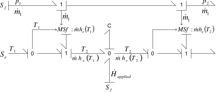
A. Bond graph model of economizer
It has been mentioned elsewhere, that pseudo power variables for thermal and hydraulic systems in process engineering are temperature (K) plus enthalpy flow (J/s), and pressure (P) plus mass flow (kg/s), respectively[12].In case of economizer, there are assumed two systems involved, i.e.
thermal and hydraulic.The multi-energy bond-graph should represent the coupling behaviors of thermal and hydraulic systems.This is done by using CETF (coupling element for thermo-fluid) as stated elsewhere in[8].It takes the following form (Fig. 2).
Fig. 2. CETF (Coupling Element for Thermo-Fluid)
A typical schematic diagram of input-process-output and bond graph model of economizer using CETF as the coupling element are shown below.
Fig. 3. Schematic diagram of input-process-output of economizer
B. Parameter estimation using GA
As an optimization tool, GA works with a set of solutions, = , , ⋯ , , called population.A population element, , is called an individual.In each iteration, GA evaluates the fitness of all the individuals in the population
and creates new population by performing operations such as combining two individuals (crossover) or changing an individual (mutation).The old population is discarded, so GA will start a new process using the new population.Every iteration is referred to as a generation.
In each generation individuals are selected for reproduction according to their performance with respect to fitness
m
&
1
T
H
&
2
T
H&
m
&
1
:mc T MSf & p
1
T
H
&
1
T
H
&
1
T
2
T
H
&
T
eco
Economizer
Waterin Waterout
Qapplied
in in in
in
m
H
T
p
&
&
out out out
out
m
H
T
p
&
&
fluid gas
H
&
→1
C
0 0 1
1
1 0
( )
1:
m
h
T
MSf
&
eMSf
:
m
&
h
e( )
T
2( )
T
2h
m
&
e( )
T
1h
m
&
eapplied
H
&
1
T
1
T
T
2T
21
p
1
m
&
1
m
&
m
&
1m
&
1 2p
e
S
f
S
f
S
International Journal of Engineering & Technology IJET-IJENS Vol: 12 No: 01 59
126701-5858 IJET-IJENS @ February 2012 IJENS
I J E N S function.The selection is done in such a way that the
individual with higher fitness value will get more chance to survive.The algorithm is terminated either after a certain number of generations or when the optimal solution has been found.
IV. RESULT AND DISCUSSION
This section will show the bond graph model of economizer and the resultingstate equations.The simulation results for step input changing and random disturbances are also discussed.
A. The governing equations
Fig.4 shows bond graph model of economizer. The C on the figure represents energy accumulator element. This type of element is viewed as enthalpy flow storage and serves to satisfy the energy conservation law.It can be directly noticed from Fig.4., thateffort variable, , is computed from accumulation of upstream enthalpy flow of economizer plus heat flow from flue gas minus downstream enthalpy flow of economizer divided by a constant, C, (1). The constant C is a heat capacity which equal to × × . The and are specific mass of water (in. ) and specific heat of water (in. . ) at temperature, and is economizer’s volume (in ). The ℎis also temperature dependent, and by the following relations
=
×
= !", (1) can be
rewritten as in (2). The heat transferred from flue gas to working fluid is influenced by overall heat transfer coefficient (Uin#$), economizer’s surface area (A in ), and temperature difference between flue gas and water inside economizer, as denoted by (3).
The flow storage element, C-field, has been identified as a differential equation where temperature output of economizer, temperature of flue gas, and boiler feed water (BFW) flow-rate are regarded as states and inputs, respectively.The governing equation is treated as a lumped parameter model as shown below.
=%& !'ℎ() + +', -− 'ℎ()" /0 (1)
1
=
23456
7'899:;5<
=3 + '(− )> (2)
1
=
23456
=3?@AB− C + '(− )> (3)
B. Finding overall heat transfer coefficient (U)
The attempt to find overall heat transfer coefficient (U) has been done in two ways, first using logarithmic temperature mean difference (LTMD) and the second isby making use of polynomial that relates boiler feed water rate, fuel flow-rate, and combustion air supply. The coefficients in the polynomial are estimated by genetic algorithm (GA) technique.
Finding U using LTMD is achievedthrough the following stages: (1) Determine the enthalpy of water at the inlet and outlet of economizer.The data needed for this purpose are: economizer’s surface area, boiler feed water flow rate, boiler
feed water inlet and outlet temperature, flue gas inlet and outlet temperature. (2) Compute the logarithmic temperature mean difference between flue gas and water.The data needed for these computation are: temperature difference of flue gas entering economizer zone and water leaving economizer(ΔE,), temperature difference of flue gas leaving economizer zone and water entering economizer(ΔEF). (3) Compute LTMD using the following relationship:ΔEG= ΔE,− ΔEF/2,3 ×
log(ΔEF/ΔEF).(4)Compute the overall heat transfer coefficient
(U) by using the following formula:N = (ℎ− ℎ) =
?@ΔEG. This equation makes use of mass flow rate, m, enthalpy of water at the inlet and outlet of economizer (h1and
h2), and economizer’s surface area, A.
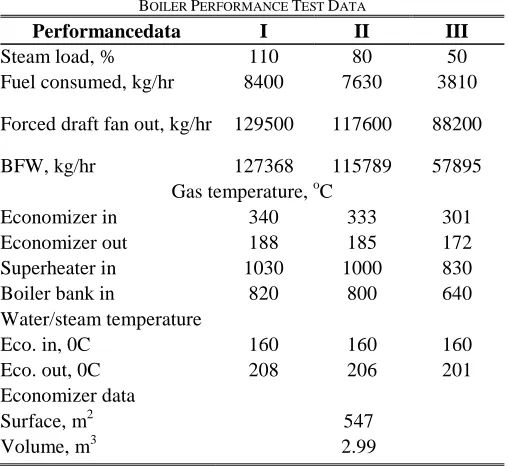
The performance test data will be used to calculate Uand simulate the model. These data are presented inTable 1 below.
TABLE 1
BOILER PERFORMANCE TEST DATA
Performancedata I II III
Steam load, % 110 80 50
Fuel consumed, kg/hr 8400 7630 3810
Forced draft fan out, kg/hr 129500 117600 88200
BFW, kg/hr 127368 115789 57895
Gas temperature, oC
Economizer in 340 333 301
Economizer out 188 185 172
Superheater in 1030 1000 830
Boiler bank in 820 800 640
Water/steam temperature
Eco. in, 0C 160 160 160
Eco. out, 0C 208 206 201
Economizer data
Surface, m2 547
Volume, m3 2.99
The enthalpy of water at corresponding temperature are computed using MATLAB function XSTEAMwhich is found in [5].
International Journal of Engineering & Technology IJET
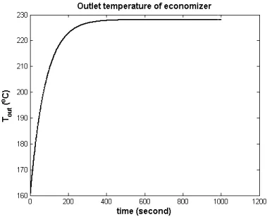
Fig. 5. Step response of economizer’soutlet temperature
MCC(? = 39,25 #$, = 232,52 ° )
Fig. 6. Step response of economizer’soutlet temperature at 80% of MCC
36,51 #$,
= 230,77 ° )
Fig. 7. Step response of economizer’soutlet temperature at
24,54 #$,
= 228,12 ° )
The simulation results show that there are discrepancies between steady state and performance test data.These are probably caused by an error in economizer surface area.Other possible sources of error are in the estimation of
transfer coefficient and economizer volume. On the other hand, estimation of U using performed through the following phases: (1) d function that will be minimized by GA, (2) d
constraint function, (3) implementing cost function and
International Journal of Engineering & Technology IJET-IJENS Vol: 12 No
126701-5858 IJET-IJENS @ February 2012 IJENS
’soutlet temperature at 110% of
temperature at 80% of MCC(? =
temperature at 50% of MCC(? =
The simulation results show that there are discrepancies between steady state and performance test data.These are probably caused by an error in economizer surface area.Other imation of overall heat
using GA has been (1) determining cost GA, (2) determining mplementing cost function and
constraint function into GA, (4) r desired solution.
Here, U is estimated using a polynomial as indicated in (4)
?Y = Z × '[\]+ ^ × '_`-+
Then the heat which is transferred working fluid is computed by (5).
NB,Y→,b= ?Y@=cA_-`− ,b
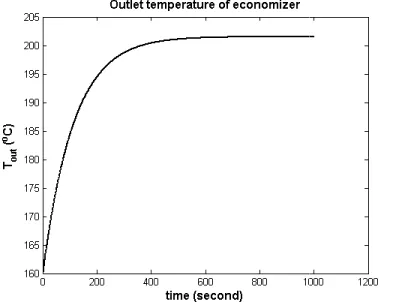
The following graphs depict the model, which employs GA for
dynamic responses of economizer’s temperature.
Fig. 8. Step response of economizer’soutlet
(? = 20,28 #$,
= 207,79 ° )
Fig. 9. Step response of economizer’soutlet
(? = 18,43 #$,
= 206 ° )
Vol: 12 No: 01 60
I J E N S GA, (4) running GA to find the
is estimated using a polynomial as indicated in (4)
× ',b (4)
Then the heat which is transferred from flue gas into
,bC (5)
the reliability of the proposed for U estimation, to imitate of economizer’s temperature.
’soutlet temperature at 110% of MCC
)
International Journal of Engineering & Technology IJET
Fig. 10. Step response of economizer’soutlet temperature at 50% of MCC
(? = 10,57 #$,
= 201,53 ° )
The above simulations are performed using polynomial suggestedin (6) where the coefficients are computed Toolbox in MATLAB with parameters indicated in Table
?Y= 0,3798'[\]+ 0,3748'_`-+ 0.166
TABLE 2
SIMULATION PARAMETERS IN MATLAB Numerical
integration method
Runge-Kutta 45
Genetic Algorithm parameters
Population 50-100
Generation 50-75
Mutation rate 0,3
Migration forward, fraction: 0,2, interval: 20
Selection Uniform stochastic
Steam Table X-Steam for MATLAB
In equation (5), _-`B,Y is not explicitly from Boiler Performance Test Data. Despite
suitability of at steady state, it is not possible to employ proposed model since_-`B,Y is not a measured
the boiler is operated.The proposed solution is roughly estimated through its correlation with fuel flow data from Table 1.
V. CONCLUSION
This paper has presented a methodology for improving the performance of economizer temperature model using bond graph and genetic algorithm.Economizer temperature behavior is described by one order lumped parameter model plus estimated parameters.A solutions for the equation is
MATLAB-Simulink environment.The models are structured as state space S-function-form of nonlinear class which are solved using numerical integration sub-routine provided in the software.The potentials of the proposed method to improve model performance are shown from simulation result compare to the designed data.
International Journal of Engineering & Technology IJET-IJENS Vol: 12 No
126701-5858 IJET-IJENS @ February 2012 IJENS
temperature at 50% of MCC
The above simulations are performed using polynomial as where the coefficients are computed using GA Toolbox in MATLAB with parameters indicated in Table 2.
166',b (6)
ATLAB
: 0,2, interval: 20
Steam for MATLAB
explicitly available except Despite a remarkable is not possible to employ the measured variable when solution is roughly estimated through its correlation with fuel flow data from
This paper has presented a methodology for improving the performance of economizer temperature model using bond h and genetic algorithm.Economizer temperature behavior is described by one order lumped parameter model plus estimated parameters.A solutions for the equation is found in Simulink environment.The models are structured of nonlinear class which are routine provided in the software.The potentials of the proposed method to improve model performance are shown from simulation result compare
REFERENCES
[1] Astrom, K. J. and Bell, R. (2000), “Drum Boiler Dynamics”,
Automatica, 36, pp 362-378.
[2] Cheres, E., (1990), “Small and Medium Size Drum Boiler Models Suitable for Long Term Dynamic Response”,
Energy Conversion, Vol. 5 No. 4, pp 686
[3] Cori, R. and Busi, T. (1977), “Parameter Identification of a Drum Boiler Power Plant”, Proc. 3rd Power Plant Dynamic
Symposium, Knoxwille, Tennessee, September 7
[4] de Mello, F. P., (1991), “Boiler Models for System Dynamic Performance Studies”, IEEE Transactions on Power Systems No. 1pp 753-761.
[5] Holmgreen, M., 2006, XSTEAM for MATLAB, www.x accessed at 30/10/2009.
[6] Kalogirou, S.A., 2003, Artificial intelligence for the modeling and
control of combustion processes: a review
Combustion Science 29 (2003) 515–566, Pergamon.
[7] McDonald, J.P. and Kwatny, H.G. (1970), “A Mathematical Model for Reheat Boiler-Turbine-Generator Systems”, in
Winter Power Meeting, New York, Paper 70 CP221
[8] Medjaher, K., Samantaray, A.K., Ould Bouamama, B., (2009),
graph model of a vertical U-tube steam
exchanger, Simulation Modeling Practice and Theory 239, Elsevier.
[9] Nazaruddin, Y.Y. and Kurniawan, I., (2001), Control of Neutralization Process by an Adaptive Neuro-Fuzzy Controller with Genetic Algorithm, In: Proc. Of The Third International Conference on Control
Theory and Application, p. 459-463, Pretoria, South Afric
[10] Nazaruddin, Y.Y. and Maulana, F., (2002), Optimizing the performance of predictive control using genetic algorithm,
Int. Conf. Intelligent System and Control
[11] Priandoko, B., Achmad, A.S., Nazaruddin, Y.Y., Sasongko, D.,
Algorithm-based Optimization in Nonlinear Predictive Control for Binary Distillation Unit, Proceed. the 3
Computation, Intelligence, Robotics and Autonomous System (CIRAS’2005), Singapore, December 13
[12] Samia, L., Mabrouk, K., Mohammded, M., (2006), Modeling and simulation of the distillation column,
Technology 5(8): 823-828, 2006.
A.N. Aziz was born in Cilacap, Indonesia, on June 16, 1974
He is a lecturer of Physics Study Progra
Soedirman University, Indonesia, since 1999. He has interest in physical modeling and simulation of complex systems, including industrial and environmental subsystems. He his Ph.D. (Application of physical modeling and neural network
boiler control systems) in 2011 from Institut Teknologi Bandung, Indonesia. He is also a member of Indonesian Physical Society.
Vol: 12 No: 01 61
I J E N S
EFERENCES
. and Bell, R. (2000), “Drum Boiler Dynamics”, Cheres, E., (1990), “Small and Medium Size Drum Boiler Models Suitable for Long Term Dynamic Response”, IEEE Transactions on
, Vol. 5 No. 4, pp 686-692.
d Busi, T. (1977), “Parameter Identification of a Drum Boiler
Power Plant Dynamic, Control and Testing
, Knoxwille, Tennessee, September 7-0, 1977
de Mello, F. P., (1991), “Boiler Models for System Dynamic
IEEE Transactions on Power Systems, Vol. 6,
Holmgreen, M., 2006, XSTEAM for MATLAB, www.x-eng.com,
Artificial intelligence for the modeling and control of combustion processes: a review, Progress in Energy and
566, Pergamon.
McDonald, J.P. and Kwatny, H.G. (1970), “A Mathematical Model for Generator Systems”, in Procs. of IEEE, PEE , New York, Paper 70 CP221-PWR.
Medjaher, K., Samantaray, A.K., Ould Bouamama, B., (2009), Bond
steam condenser coupled with a heat Simulation Modeling Practice and Theory, 17 (2009)
228-Nazaruddin, Y.Y. and Kurniawan, I., (2001), Control of Neutralization Fuzzy Controller with Genetic
In: Proc. Of The Third International Conference on Control
463, Pretoria, South Africa
Nazaruddin, Y.Y. and Maulana, F., (2002), Optimizing the performance of predictive control using genetic algorithm, In: Proc. Of The IASTED
Int. Conf. Intelligent System and Control, p.233-238
Priandoko, B., Achmad, A.S., Nazaruddin, Y.Y., Sasongko, D., Genetic
based Optimization in Nonlinear Predictive Control for
Proceed. the 3rd International Conference on
Computation, Intelligence, Robotics and Autonomous System (CIRAS’2005), Singapore, December 13-16, 2005.
L., Mabrouk, K., Mohammded, M., (2006), Modeling and simulation of the distillation column, Asian Journal of Information