IJIRT 100046
INTERNATONAL JOURNAL OF INNOVATIVE RESEARCH IN TECHNOLOGY32
Performance and Analysis of Viterbi Decoder Using
VHDL
Er.Mandeep Singh
Dept of ECE Yadwindra College of Eng.
Talwandi Sabo Bathinda Pb.
Abstract- Convolutional encoding is a forward error correction technique that is used for correction of errors at the receiver end. The two decoding algorithms used for decoding the convolutional codes are Viterbi algorithm and Sequential algorithm. Sequential decoding has advantage that it can perform very well with long constraint length. Convolutional codes, but it has a variable decoding time. Viterbi decoding is the best technique for decoding the convolutional codes but it is limited to smaller constraint lengths. The basic building blocks of Viterbi decoder are branch metric unit, add compare and select unit and survivor memory management unit. The two techniques for decoding the data are traceback (TB) method and Register Exchange (RE) method. TB method is used for longer constraint lengths but is has larger decoding time. Also extra circuitry is required to reverse the decoded bits. The RE method is simpler and faster than the TB method for implementing the VD. RE method is not appropriate for decoders with long constraint lengths. Viterbi decoder is implemented on FPGA. FPGAs reprogrammability and high degree of parallelism attracts them for DSP applications. The hardware description language VHDL is used to describe the design. The design is synthesized using Xilinx Project Navigator software and simulated using Model-Sim.
I. VITERBI ALGORITHM
Figure 1 a simple Viterbi decoding system [8]
A.J. Viterbi proposed an algorithm as an ‘asymptotically optimum’ approach to the decoding of convolutional codes in memory-less noise. The Viterbi algorithm (VA) had already been known as a maximum likelihood decoding algorithm for convolutional codes. As it is showing in the figure, a data sequence x is encoded to generate a convolutional code word y. after y is transmitted through a noisy channel. The convolutional decoder takes the received vector r and generates an estimate z of the transmitted code word. The initial part first initializes the Viterbi decoder to the same FSM and trellis diagram as convolutional encoder as 6 then in each time clock, the decoder computers the four possible branch metric’s hamming distance. For each state, ACS block compute the two possible paths Hamming distance and select a small one. ACS block will record the survivor state. A trellis structure is built along the way, where each state transition is noted with all the relavent information like path metric and the decision bit. When all the data bits have been received, and the trellis has been completed, the last stage of the trellis is used as the starting point for tracing back. The trace-back operation outputs the decoded data, as it traces back along the maximum likelihood path.
IJIRT 100046
INTERNATONAL JOURNAL OF INNOVATIVE RESEARCH IN TECHNOLOGY33
Figure 2 the flow chat of the Viterbi decoding [8].
A. Convolutional Encoding
The convolutional encoder is basically a finite state machine. The k bit input is fed to the constraint length K shift register and the n outputs are calculated from the generator polynomials by the modulo-2 addition. The generator polynomial specifies the connections of the encoder to the modulo-2 adder. The 1 in the generator polynomial indicates the connections and 0 indicates no connections between the stage and the modulo 2 adder.
Figure 3: Convolution encoder [8]
state table, state diagram and trellis diagram. The State is defined as the contents of the shift register of the encoder. In state table output symbol can be described as a function of input symbol and the state. State diagram shows the transition between different states. Trellis diagram is the description of state diagram of the encoder by a time line i.e. to represent each time unit with a separate state diagram.
Figure 4: State Table[8]
IJIRT 100046
INTERNATONAL JOURNAL OF INNOVATIVE RESEARCH IN TECHNOLOGY34
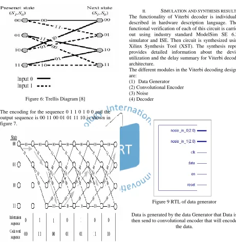
Figure 6: Trellis Diagram [8]
The encoding for the sequence 0 1 1 0 1 0 0 and the output sequence is 00 11 00 01 01 11 10 is shown in figure 7.
Figure 7: Trellis Diagram for Encoder [8]
II. SIMULATION AND SYNTHESIS RESULT
The functionality of Viterbi decoder is individually described in hardware description language. Then functional verification of each of this circuit is carried out using industry standard ModelSim SE 6.2g simulator and ISE. Then circuit is synthesized using Xilinx Synthesis Tool (XST). The synthesis report provides detailed information about the device utilization and the delay summary for Viterbi decoder architecture.
The different modules in the Viterbi decoding design are:
(1) Data Generator (2) Convolutional Encoder (3) Noise
(4) Decoder
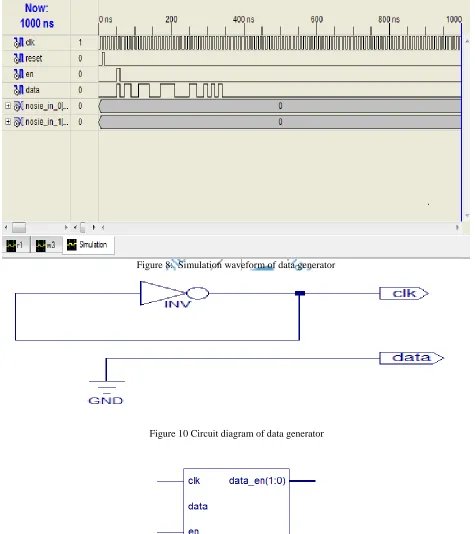
Figure 9 RTL of data generator
Data is generated by the data Generator that Data is then send to convolutional encoder that will encode
IJIRT 100046
INTERNATONAL JOURNAL OF INNOVATIVE RESEARCH IN TECHNOLOGY35
Figure 8: Simulation waveform of data generator
Figure 10 Circuit diagram of data generator
Figure 11: RTL of Convolutional encoder
IJIRT 100046
INTERNATONAL JOURNAL OF INNOVATIVE RESEARCH IN TECHNOLOGY36
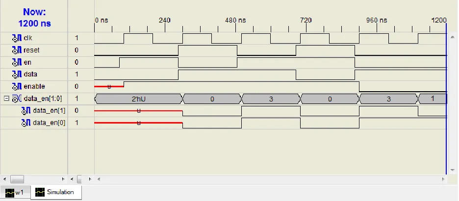
Figure 12: Simulation Waveform of Convolutional encoder
Figure 13: Circuit diagram of convolutional encoder
IJIRT 100046
INTERNATONAL JOURNAL OF INNOVATIVE RESEARCH IN TECHNOLOGY37
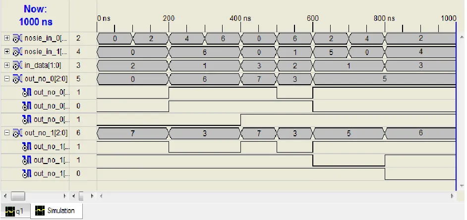
Figure 15: Simulation waveform of noise generator
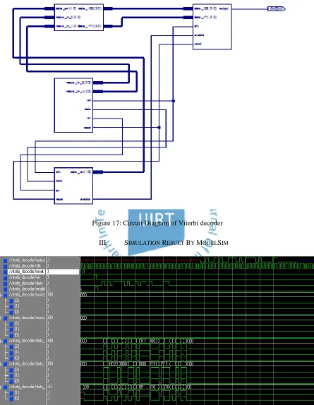
Next block is the viterbi decoder that decodes the data from convolutional encoder which travel in some medium or channel some noise is added in that and then this is decoded by the viterbi decoder. After the data is decoded by the Viterbi decoder the output of waveform is as shown below:
IJIRT 100046
INTERNATONAL JOURNAL OF INNOVATIVE RESEARCH IN TECHNOLOGY38
Figure 17: Circuit Diagram of Viterbi decoder
III. SIMULATION RESULT BY MODELSIM
Figure 18: simulation Waveform of viterbi decoder in ModelSim
IJIRT 100046
INTERNATONAL JOURNAL OF INNOVATIVE RESEARCH IN TECHNOLOGY39
Numbers of Slices (6912)
3498 (50%)
Number of Slice Flip-Flops (13824)
3473 (25%)
Number of 4LUTS (13824)
5444 (39%)
Number of Bonded IOB’s (329)
1 (0%)
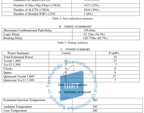
Table 2: Area utilization summary
B. TIMING SUMMMARY
Maximum Combinational Path Delay
195.84ns
Logic Delay
67.12ns (34.3%)
Routing Delay
128.770ns (65.7%)
Table 3: Timing summary
C. POWER SUMMARY
Power Summary
I (mA)
P (mW)
Total Estimated Power
34
Vccint 1.80V
15
27
Vcc33 3.30V
2
7
Clocks
0
0
Inputs
0
0
Quiescent Vccint 1.80V
15
27
Quiescent Vcc33 3.30V
2
7
Table 4: Power summary
D. THERMAL SUMMARY
Estimated Junction Temperature
26C
Ambient Temperature
25C
Case Temperature
26C
Table 5: Thermal Summary
IV. CONCLUSION
Viterbi decoding is the best technique for decoding the convolutional codes. Viterbi decoder with constraint length 7 and code rate 1/2 has been developed. The main consideration is to decode for longer constraint lengths. The two techniques used for decoding the convolution codes are the RE method and TB method. TB method is used for larger constraint length where RE is not used for longer constraint length.
V. FUTURE SCOPE
In future Viterbi decoder with Modified Register Exchange Method can be further investigated for higher constraint lengths and lower power
consumption then that of Viterbi decoder using register exchange method and trace back method.
REFERENCES
[1]. Janne Maunu, Mika Laiho, Ari Paasio“ A Differential Architecture for an Analog Viterbi Decoder”,IEEE Transcations on Circuits And Systems—1, VOL. 55, NO. 4, MAY 2008.
[2]. Russell Henning,Chaitali Chakrabarti“An Approach for Adaptively Approximating the Viterbi Algorithm to Reduce Power Consumption While Decoding Convolutional Codes” IEEE Transactions On Signal Processing, VOL. 52, NO. 5, MAY 2004.
IJIRT 100046
INTERNATONAL JOURNAL OF INNOVATIVE RESEARCH IN TECHNOLOGY40
NO. 5, MAY 2007.[4]. Kyu-Man Lee, Do.ng-Seog Han’ and Ki-Bum Kim“ Performance of the Viterbi decoder for DVB_T, “IEEE Transcation on Consumer
Electronics-1, VOL.44, NO.3, AUGUST 1998.
[5]. Dong-Sun Kim, Seung-Yerl Lee, Kyu-Yeul Wang “Power Efficient Viterbi Decoder based On Pre- Computation Technique for Potable Digital Multimedia Broadcasting Recivier ,”IEEE on
Consumer Electronics ,VOL.53 NO.2 MAY 2007.
[6]. K. S. Arunlal, Dr. S. A. Hariprasad “ An Efficient Viterbi Decoder” International Journal of
Advanced Information Technology (IJAIT) VOL. 2, NO.1, FEBRUARY 2012.
Xinming Huang, and Kai Zhang” High-Speed Low- power Viterbi Decoder Design for TCM Decoders”
IEEE Transaction on very large Scale integration (VLSI) Systems, VOL. 20, NO. 4, APRIL 2012.
[8]. Pushpinder Kaur, “Implementation Of Low
Power Viterbi Decoder On FPGA”International
Journal of AdvancednInformation Technology
(IJAIT) VOL. 2, NO.1,JUNE, 2006.
![Figure 4: State Table[8]](https://thumb-us.123doks.com/thumbv2/123dok_us/1402316.1652315/2.612.80.547.80.688/figure-state-table.webp)