Abstract—TCC consists of timber and concrete members acting compositely together. The strength, stiffness, location and number of connectors play a crucial role for the composite action and structural performance of TCCs.
In upgrading of timber floor to TCC, existing floorboards can be used as a permanent formwork whilst the concrete is then poured over connectors inserted into timber floorboards. Hence, the influence of interlayer on mechanical properties of TCC joints and floor is of interest.
To date, conventional concrete has been used in most investigations on TCCs. Self-compacting concrete (SCC) is recognized as a highly workable which is compacted without use of conventional vibration methods. As such, there is a potential for application of SCC in TCCs where the pumping, and compacting of conventional concrete poses a challenge e.g. difficult to access areas in the renovation of timber floors in multi-story buildings.
This paper focuses on utilizing mechanical fasteners for their ductility and stiffness to connect a SCC slab (with and without interlayer) to a timber beam, that is, the use of SCC forms an important parameter of this research. The experiment consists of push-out tests to characterizeload capacity and various stiffness. The responses of the specimens are also compared to that of TCCs with conventional concrete.
Index Terms—Timber concrete composite (TCC), interlayer, self-compacting concrete (SCC), SFS screw connection.
I. INTRODUCTION
TCC system consists of a timber base supporting a concrete slab and composite action between the two layers is achieved through various types of shear connection which transfer shear forces and impedes slip between the members. Hence, the strength, stiffness, location and number of connectors are identified as significant parameters for the composite action and the structural and serviceability performance of TCC solutions [1], [2].
To date, conventional concrete (NC) has been applied in most investigations on TCCs. There are only few investigations to study the effect of concrete properties on the structural behavior of TCC system. With the advance in high performance concrete, concrete mixes can be designed to new requirements of strength and serviceability such as self-compacting concrete (SCC), light-weight concrete (LWC) and fiber reinforced concrete (FRC) [3]. The fresh properties of concrete are in retrofit of old timber floor as
Manuscript received May 14, 2014; revised June 28, 2014. This work was supported by Structural Timber Innovation Company (STIC).
The authors are with University of Technology, Sydney, Australia (e-mail: [email protected], [email protected], [email protected]).
TCC is of interest for two reasons;the concrete needs to be workable and compactable in order to fill the formwork properly. Moreover, concrete needs to be pumpable as some locations, particularly in retrofits may not be able to be reached by crane [3].
SCC has been used increasingly for more than two decades in pre-cast concrete technology whilst its application in TCC provides a potential development to enhance the workability and flow ability of concrete without the need for an external vibration [3], [4]. The components of SCC and NC are identical consisting of cement, water, aggregates, admixtures, and mineral additions but the composition of the mixture, fresh and hardened properties are different. SCC includes larger amount of mineral fillers (i.e. finely crushed limestone or fly ash) and water-reducing admixtures. Moreover, the maximum size of coarse aggregate is smaller than that in NC.
In upgrading of old timber floors using TCC construction, existing floorboards can be used as permanent formwork in form of an interlayer between the timber beams and concrete slab. Mechanical shear connections can be mounted into timber joists at regular spacing and concrete is then poured over existing timber floorboard. Such permanent formworks are advantageous in terms of savings on labor costs associated with demolishing the existing floor and construction of new formwork. Moreover, it creates less disturbance to the building and prevents any possible concrete leakage [5]. Previous investigations including [6] and [5] identified that the interlayer creates a gap between the timber and concrete members which results in lower slip modulus and load capacity of TCC connection. Further investigations on influence of interlayer on mechanical properties of TCC floor using normal concrete and SCC can improve design codes and its practical applications in upgrading of old timber floor.
A. Connection Description
The investigation presented in this paper studies the influence of interlayer on mechanical properties of TCC joints using self-compacting concrete and normal concrete slabs.
The experimental aspect of the research consists of push-out tests on TCC specimens with and without plywood interlayer and fabricated with SCC using dual SFS intec screws as shear connectors. Load-slip response, slip modulus, load carrying capacity and failure modes are investigated. The responses of the SCC specimens are also compared to identical specimens fabricated with conventional concrete.
A total of twenty samples were prepared with two different concrete mixes, NC ( mass per unit volume 2400 kg/m3, 28-day compressive strength 32MPa, MOE=33.2 GPa) and
The Effect of Interlayer on the Structural Behavior of
Timber Concrete Composite Utilizing Self-Compacting
and Conventional Concretes
SCC (mass per unit volume 2500 kg/m3, 28-day compressive
strength 35 MPa, MOE=35.4 GPa). Ten of the samples (five for each concrete type) were fabricated to include a plywood interlayer while the remaining ten specimens had no interlayer between timber and concrete. Details of the tested samples are shown in Fig. 1.
(a)
(b)
(c)
Fig. 1. Typical geometry and components of specimens: (a) cross-section of specimen without interlayer (WI series), (b) cross-section of specimen with
interlayer (I series) (c) plan (in mm).
B. Concrete Properties
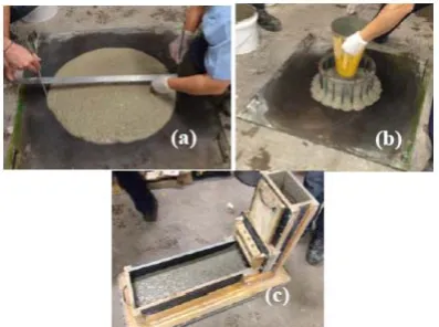
The fresh properties of SCC i.e. flowability, passing ability and filling ability of the SCC mix were measured using different test methods such as slump-flow, J ring and L Box funnel as demonstrated in Fig. 2. The mix designs of each type of the concrete used are tabulated in Table I.
Fig. 2. (a) Slump-flow (b) J ring and (c) L box tests of workability in SCC.
TABLEI:CONCRETE MIX DESIGNS
Water reducer, superplasticiser and viscosity modifying admixture were used to adjust the mix design. Once concrete
was poured into the specimens, they were covered by plastic sheets to cure in a controlled environment and reduce speed of the hydration process. After 7 days the TCC specimens were demoulded and the specimens were exposed to an indoor laboratory environment (T=20°, RH=65%) until testing.
The slump flow test was used to give an indication on the flowability, passing ability and yield stress of SCC. The test involves filling an Abram’s Cone with the SCC and placing it in the center of a slump flow board complying with [7]. The Abram’s Cone was lifted to a height of approximately 230 mm in 3 seconds and allowing the concrete to flow out onto the slump flow board in a circular shape. The slump flow diameter is then measured as the diameter of the circle of concrete within two directions (d1 / d2) as demonstrated in Fig.
2a. The mix was required to reach a slump diameter of 680 mm and the mix was determined to be in compliance after the slump flow test was completed.
The J Ring test was carried out to measure the passing ability of the SCC mix through blockage. The J Ring test is very similar to the slump-flow test, the only difference being the incorporation of the J Ring which is placed in the center of the slump-flow board and in which the Abram’s Cone sits inside. The Abram’s Cone is lifted to a height of approximately 230 mm over 3 seconds and the mix flows outwards through the reinforcing bars on the J Ring. Slump-flow diameter is again measured along with the time the mix takes to flow to its final testing position. The testing procedure for J Ring test is depicted in Fig. 2b. The concrete reached a diameter of 655 mm in the J Ring test. This was compared with the slump flow test diameter of 680 mm, creating a difference of 25 mm. Appropriate passing ability is indicated by a diameter difference of less than 25 mm, meaning the SCC mix was determined to have adequate passing ability.
The L Box test assesses the flowability and passing ability of the SCC mix whilst the concrete is subjected to blockage by reinforcement [8]. The L Box consists of a vertical column connected to a long horizontal section, and the two are separated by a gate and a set of rebar as displayed in Fig. 2c. Each of the two sections has approximately the same volume; the test starts by closing gate and then filling the vertical column with the SCC to the top. Once the column in filled the gate is opened and the concrete is allowed to flow through the gate and the rebar to fill the horizontal section.
The flowability is determined by observing the ratio of the height of the concrete at the end of the horizontal section to the height of the concrete next to the vertical column. [8] proposed that a mix with adequate flowability has a ratio of 0.8-1.0 or greater. In the test, the ratio was approximately 0.94 meaning that the mix had adequate flowability. The passing ability was also determined to be adequate by carrying out a visual inspection, which indicated an even distribution of the aggregate around the rebar.
C. Timber (LVL)
Table II.
TABLEII:MECHANICAL PROPERTY OF TIMBER
Mechanical property Value (MPa)
Veneer Species Radiata Pine
Density 560 - 650 kg/m3
Modulus of Elasticity (E) 13.200 GPa Modulus of Rigidity (G) 660 MPa Characteristic Stress in bending (fb) 44.6 Mpa Characteristic Stress in tension parallel to grain (ft) 23.8 Mpa Characteristic Stress in compression parallel to grain (fc) 41 MPa Characteristic Stress in compression transverse to grain (fp) 12 MPa
Characteristic Stress in longitudinal shear (fs) 4.6 MPa
D. Shear Connection
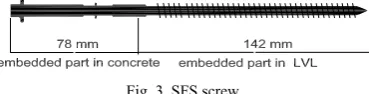
The shear connections used in the specimens comprised of dual VB-48-7.5×165 SFS intec screws embedded into the timber at ±45° as depicted in Fig. 3.
Fig. 3. SFS screw.
The SFS screw connectors were developed in 1992 by Meierhofer and were specifically designed for TCC structures, either in the construction of new flooring systems or the rehabilitation of existing timber floors. The screws were placed at the mid-point of the composite interface of TCC joint specimens and a guide was used to ensure consistent placement and precise angling of the screws. Each hole was predrilled for the majority of the length of insertion. Screws were inserted so that the thread was fully in the timber/interlayer (a length of 142mm). This meant a length of approximately 78mm (along the axis of the screw, 55mm vertically in slab) was embedded in the concrete (as such, samples with interlayers had less length within the LVL as screws also had to penetrate through the interlayer).
Application of SFS screws in TCC system were extensively investigated in literatures such as [1], [2], [5], [6], [9]-[14].
E. Test Set-up, Test Procedure and Data Recording
The push out tests were conducted after 28 days of curing to measure the effectiveness of the shear connection in terms of its strength and stiffness. Measuring the applied load and the slip at the interface between the timber and the concrete, load-slip response of connections were plotted from which the slip modulus and the stiffness of the connection were obtained.
The TCC specimens were held upright in a steel frame as test rig. The specimens were placed so that the free end of the timber was at the top where the load was to be applied as shown in Fig. 4.
The inclusion of a steel block which was placed on top of the timber ensured that uniform load distribution was being achieved. A load cell and three Linear Variable Differential Transformers (LVDTs) were applied to measure data. The testing procedure was speed controlled in accordance with the provisions of [15] which sets a required loading sequence. The samples are loaded to 40% of anticipated failure load,
Fest over a period of two minutes.
The load is then maintained at this level for 30 seconds, before being reduced to 10% of Fest over a period of 90
seconds and is held at this level for a further 30 seconds. Following this, the sample is loaded at a continuous rate until failure and the failure modes have been investigated.
Fig. 4. Set-up of a specimen in the test rig: (a) front and (b) back views.
II. EXPERIMENTAL RESULTS AND DISCUSSION During push out test, the applied load and the corresponding slip at the three locations of the LVDTs were measured. The load-slip responses of the test series are shown in Fig. 5.
Fig. 5. Load-slip curves for different test series.
Stiffness and the 5th percentile strength of the TCC connections were calculated based on the formulas in compliance with CEN (1991) and [16], respectively. Comparing NC and SCC series, the influence of the concrete properties on strength and stiffness of joints were investigated whilst by inclusion of the plywood interlayer in with interlayer series, the strength and stiffness of with interlayer series were compared to that of without interlayer series. Moreover, the failure modes of the connections are also studied.
TABLEIII:STRENGTH OF DIFFERENT TEST SERIES
Test series specimenscapacity (kN) Mean load Strength Qk
(kN) σ CoV (%) conventional WI 5 33.25 31.6 1.58 4.75% SCC WI 3 34.6 32.95 1.3 3.76% conventional I 5 31.04 29.39 0.94 3.03% SCC I 5 29.46 27.81 0.73 2.48%
A. Strength Analysis
The values of maximum load carrying capacity and the 5th percentile strength (Qk) of TCC joint of four different test
series are tabulated in Table III.
inclusion of interlayer also reduced the load capacity of NC and SCC test series about 7% and 15%, respectively as listed in Table III.
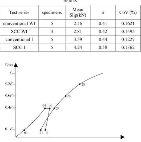
Table IV indicates the average slip at maximum load carrying capacity of different test series.
Application of an interlayer in SCC and NC series increase the slip at maximum load carrying capacity about 51% and 40%, respectively.
B. Stiffness Analysis
Three different slip moduli corresponding to serviceability, ultimate and near collapse of TCC joint were derived from the load-slip diagram based on CEN (1991) using the slip measurements at specified points as shown in Fig. 6.
TABLEIV:SLIP AT MAXIMUM LOAD CAPACITY FOR DIFFERENT TEST
SERIES
Test series specimens Slip(kN) Mean σ CoV (%)
conventional WI 5 2.56 0.41 0.1621
SCC WI 3 2.81 0.42 0.1495
conventional I 5 3.59 0.44 0.1227
SCC I 5 4.24 0.58 0.1362
Force
Fest
0.8Fest
0.4Fest
0.1Fest
Joint slip, v 0.6Fest
01 21 11
04 14 24
26 28
Fig. 6. Load-slip curve from push out tests in compliance with CEN (1991).
Plotting load-slip responses of the connections, the slip moduli and the serviceability slip modulus, Ks,0.4 was
calculated based on 0.4Fmax (Fmax is the load carrying
capacity) as demonstrated in (1) whilst the ultimate slip modulus, Ku,0.4 was calculated based on 0.6 Fmax as given in
(2). Finally the near collapse slip modulus, K0.8 was calculated based on 0.8 Fmax as shown in (3).
) ( 3 4 4 0 01 04 max 4 0 υ υ F . = Ks,.
−
(1) 24 26 01 04 max 6 0 ) ( 3 4 6 0 υ υ υ υ F . =
Ku,.
− + −
(2) 24 28 01 04 max 8 0 ) ( 3 4 8 0 υ υ υ υ F . =
Ku,.
− + −
(3)
Three different slip moduli corresponding to serviceability, ultimate and 0.8 Fmax of TCC joint are illustrated in Table V
Application of SCC instead of NC in WI series reduced
different slip moduli including Ks,0.4, Ku,0.6 and Ku,0.8 about
20%, 40% and 30% whilst a similar reduction ranging 20%-27% were observed in slip moduli of SCC I series rather than NC I series.
TABLEV:SLIP MODULI OF DIFFERENT TEST SERIES
Test series specimens slip modulus Mean(kN/mm) σ CoV(%)
NC WI 5
Ks,0.4 28.8 14.66 51%
Ku,0.6 26.63 10.15 38%
Ku,0.8 23.37 7.24 31%
SCC WI 3
Ks,0.4 22.69 1.52 6.70%
Ku,0.6 18.95 1.21 6.40%
Ku,0.8 17.08 0.6 3.50%
NC I 5
Ks,0.4 15.19 1.54 10.14%
Ku,0.6 15.4 1.07 6.95%
Ku,0.8 14.2 1 7.04%
SCC I 5
Ks,0.4 12.61 219.00% 0.173
Ku,0.6 12.48 196.00% 0.157 Ku,0.8 11.17 140.00% 0.125
Inclusion of an interlayer led to a significant reduction in slip modulus of NC and SCC test series (ranging from 35-47%), as listed in TABLE V.
Elsewhere, [6] tested TCC joints using conventional concrete in specimens with and without interlayer and concluded 55% and 45% reductions in Ks,0.4 for the specimens
with 19 and 28 mm interlayers, respectively. Such reductions agree with this study where inclusion of interlayer in both NC and SCC series lead to a reduction of approximately 45% in the serviceability slip modulus.
C. Failure Mode Analysis
The failure of screws as well as angle of screws at the plane of connection and state of concrete and timber around connection as failure mechanism of specimen was of interest. The general failure of different test series as tensile failure of screw placed in tension is illustrated in Fig. 7.
Fig. 7. Typical failure of test series.
Fig. 8. (a) Failure of tensile screws and opened specimens of screws in (b) tension and (c) compression in NC WI series.
indicated in Fig. 8-Fig. 11.
Fig. 9. (a) Failure of tensile screws and opened specimens of screws in (b) tension and (c) compression in NC Iseries.
Fig. 10. (a) Failure of tensile screw and opened specimens of screws in (b) tension and (c) compression in SCC WI series.
Fig. 11. (a) Failure of tensile screw and opened specimens of screws in (b) tension and (c) compression in SCC I series.
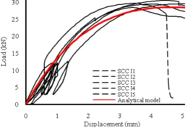
As demonstrated in Fig. 5, the behaviour of the SCC specimens (WI and I series) was fairly consistent. The load increased quite steadily, slowing slightly before peaking. Most of the specimens reaching a maximum load of around 30-35 kN following which the load gradually reduced to around 80-90% Fmax before a sudden failure occurred. This
means that the composites failed due to a tensile failure in the screw in all cases, with shear being a contributor. Necking was evident in the tension screw in all cases, further highlighting a tensile failure after undergoing plastic deformation. A total deflection of 2.8 - 4.2 mm was measured across the specimens. Furthermore, the screws failed at their narrowest point, located 10-20 mm above the thread and embedded in the concrete.
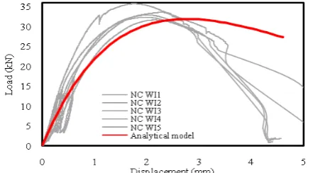
The behaviour of the NC specimens (WI and I series) was also fairly consistent. In a similar fashion to the SCC series, the load increased quite steadily, slowing slightly before reaching the peak load at around 31-33 kN. Following the peak load, load gradually reduced to around 80-90% Fmax
before a sudden failure occurred.
Split specimens as shown in Fig. 8 to Fig. 11 indicate that the composites failed due to a tensile failure in the screw, with shear being a contributor and localised damage in surrounding concrete. Necking was evident in the tension screw in all test series, further highlighting a tensile failure after undergoing plastic deformation. A total deflection of 2.5 -3.6 mm was recorded across the specimens, which was slightly lower than that of SCC series.
III. MATHEMATICAL MODEL FOR RESPONSES OF THE SERIES The mathematical expressions descriptive model of each connections test series is proposed using the load-slip
response of the connections and non-linear regression. The load-slip response of test series is divided into two part as the pre-peak and post-peak. The load increased quite steadily, slowing slightly before peak load (Fmax) is reached whilst
after reaching the peak, the load gradually reduced to around 80-90% Fmax before a sudden failure of tensile screw
occurred. The pre-peak and post-peak parts of the load-slip responses of different series (before the sudden failure) is considered for mathematical expression. Equation (4) indicates the exponential function with three unknown parameters (a, b and c) which is fitted into each test series whilst indicates slip at interface of composite materials.
) (
=a e-bυ e-cυ
P −
(4)
The mathematical expression and its R-squared of each test series are proposed in (5) to (8). R-squared indicates the square of the sample correlation coefficient between the experimental results and the mathematical expressions. Fig. 12 to Fig. 15 indicates the mathematical expressions and load-slip responses for different test series separately.
SCC WI:
) 95 . 0 ( , ) 25.3(
7
= e0.25 −e0.28 R2=
P - υ - υ
(5) SCC I:
) 98 . 0 ( , ) 61.7(
8
= e0.20 −e0.23 R2=
P - υ - υ (6)
NC WI:
) 92 . 0 ( , ) 64.5(
8
= e0.34 −e0.38 R2=
P - υ - υ
(7)
NC I:
) 97 . 0 ( , ) 235(
1
= e0.22 −e0.24 R2 =
P - υ - υ
(8)
Fig. 12. Load-slip responses and mathematical expression for SCC WI series.
Fig. 14. Load-slip responses and mathematical expression for NC WI series.
Fig. 15. Load-slip responses and mathematical expression for NC I series.
IV. CONCLUSIONS
Investigation on presence of interlayer and its influence on mechanical properties of TCC connections and floors can contribute to achieving more accurate and reliable design practices which result in safer applications in upgrading old timber floor where existing floor boards take the form of an interlayer in the TCC floor.
Self-compacting concrete represents a workable and compactable concrete which is promising for application in TCC systems where the pumping, placing and compaction of conventional concrete is a significant challenge such as in the renovation of existing timber floors in multi-story buildings. Application of SCC and its influence on mechanical properties of TCC joint have been studied in this paper. In addition mathematical expressions for different test series were proposed. This work increased the understanding of key parameters of strength, stiffness and failure mechanism of TCC joints employing LVL, NC, SCC and plywood formwork as interlayer.
It is of interest to note that the presence of an interlayer is undesirable for the strength and stiffness of TCCs. For example, the inclusion of an interlayer in both SCC and NC series decreased the load carrying capacity of the TCC joints by approximately 7-15% whilst the interlayer results in significant reduction of both, the serviceability and ultimate slip moduli of SCC and NC series (ranging 20-40%).
The general load-slip responses and failure mode of SCC series indicates a similar trend as with conventional concrete. However, application of SCC reduces serviceability slip modulus by about 20% but no significant reduction in strength of the connections could be observed. The lower stiffness of TCC joints with SCC might limit its application.
The failure mode of all the test series were caused by the yielding of the SFS screws in tension, and can be classed as a ductile failure. This is promising for the application of TCCs
implementing SFS screws in structural application, since the connections are capable of deforming substantially exhibiting visible deflections in the overall system before failure occurs.
ACKNOWLEDGMENT
The authors gratefully acknowledge the financial support of Structural Timber Innovation Company (STIC). The authors also would like acknowledge Mr Rami Haddad, Civil Engineering Laboratories Manager and Mr Peter Brown, Senior Project Engineer at University of Technology Sydney (UTS), for their assistance during the experimental tests.
REFERENCES
[1] F. Moshiri, C. Garven, C. Gerber, H. R. Valipour, R. Shrestha, and K.. Crews, "An investigation on tcc systems using light-weight concrete," presented at World Conference on Timber Engineering (WCTE)2012, New Zealand.
[2] F. Moshiri, K. Crews, C. Gerber, H. R. Valipour, R. Shrestha, and C. Garven, "The effect of interlayer on the structural behaviour of timber concrete composite joints using light-weight and conventional concrete," in Diversity in Composites 2012, Composite Australia: Leura, New South Wales, Australia.
[3] Kieslich and Holschemacher, "Composite constructions of timber and high-performance concrete," Advanced Material Research, pp. 133-134, 2010.
[4] A. Ramezanianpour, M. Samadian, and M. Mahdikhani, "Engineering properties and durability of self-consolidating concretes (SCC) containing volcanic pumice ash," Asian Journal of Civil Engineering (Building and Housing), vol. 13, no. 4, pp. 521-530, 2012.
[5] L. F. Jorge, S. M. R. Lopes, and H. Cruz, "Interlayer influence on Timber-LWAC composite structures with screw connections," Journal of Structural Engineering, vol. 137, no. 5, pp. 618-624, 2011. [6] M. L. R. Van der Linden, Timber-Concrete Composite Floor Systems,
Delft University Press, 1999.
[7] ASTMC143, Standard Test Method for Slump of Hydraulic-Cement Concrete, 2012, ASTM International West Conshohocken, PA. [8] EFNARC, European guidelines for self-compacting concrete:
specification, production and use, 2005.
[9] H. J. Blass, J. Ehlbeck, M. Van der Linden, and M. Schlager, Trag- und
Verformungsverhalten von Holz-Beton-Verbundkonstruktionen,
Universität Karlsruhe Bericht T 2710: Karlsruhe, 1995.
[10] A. Frangi and M. Fontana, "Elasto-plastic model for timber-concrete composite beams with ductile connection," Structural Engineering International, vol. 13, pp. 47-57, 2003.
[11] E. Steinberg, R. Selle, and T. Faust, "Connectors for timber–lightweight concrete composite," Journal of Structural Engineering, vol. 129, no. 11, pp. 1538-1545, 2003.
[12] R. Grantham, V. Enjily, M. Fragiacomo, C. Nogarol, I. Zidaric, and C. Amadio, "Potential upgrade of timber frame buildings in the UK using timber-concrete composites," presented at World Conference on Timber Engineering (WCTE) 2004: Lathi, Finland.
[13] E. Lukaszewska, "Development of prefabricated timber-concrete composite floors," PhD thesis, Lulea: Universitetstryckeriet, Luleå. 2009
[14] L. F. C. Jorge, J. Schänzlin, S. M. R. Lopes, H. Cruz, and U. Kuhlmann, "Time-dependent behaviour of timber lightweight concrete composite floors," Engineering Structures, vol. 32, no. 12, pp. 3966-3973, 2010. [15] EN26891, Timber Structures - Joints Made with Mechanical Fasteners
in General Principles for the Determination of Strength and
Deformation Characteristics 1991, European Committee for
Standardization: Brussels, Belgium.
Farzad Moshiri was born in 1983 in Iran. Farzad is a PhD candidate in structural engineering at University of Technology Sydney, Australia.
His PhD thesis is focuses on structural behaviour of timber concrete composite floor under supervision of Prof. Keith Crews.
He has completed his Erasmus Mondus MSc. in Earthquake engineering at Joseph Fourier University Grenoble 1, France and Rose school Pavia University, Italy.
In addition, he has done his MSc. of structural engineering with specialization in timber structure at Linnaeus University, Växjö, Sweden. He has been an author of several technical papers in his research areas.
Rijun Shrestha is a lecturer at the University of Technology Sydney (UTS) and a core member of the Centre for Built Infrastructure Research (CBIR). He received his PhD from UTS in 2009 and has been actively involved in research on timber, timber-concrete composites; fiber reinforced polymers and engineered bamboo. He has authored several journal and technical papers in his research areas and is supervising a number of undergraduate and postgraduate students.
Keith Crews is an internationally recognised expert in the area of sustainable infrastructure – particularly in regard to bridge safety, structural assessment and timber engineering for non residential buildings and physical infrastructure.