J Wood Sci (2002) 48:171-178 9 The Japan Wood Research Society 2002
S v e r k e r A n d r e a s s o n 9 M o t o i Y a s u m u r a L a u r e n t D a u d e v i l l e
Sensitivity study of the finite element model for wood-framed shear walls
Received: May 21, 2001 / Accepted: July 25, 2001
A b s t r a c t A sensitivity study was performed with a nonlin- ear elastic finite element model for monotonic analyses of wood-framed shear walls. The objective was to provide in- formation about simplifying a model of wood-framed shear walls with no significant loss in accuracy. The simplifications concern features such as slips in joints between frame mem- bers, slips in hold-down connections, and bearing between adjacent sheathing panels. The results from analyses of a shear wall with an opening of window shape show that the effect of constraint by the bearing between sheathing panels and slips in frame joints on the overall stiffness of the wall is limited. Thus, there are great possibilities for reducing the calculation time by not taking these p h e n o m e n a into ac- count, avoiding an excessive number of degrees of freedom and iterations. The influence of the simplifications on the distribution of vertical reaction forces along the wall is more significant. Furthermore, if each simplification is introduced separately, the effect on the overall stiffness is greater. The difference, however, is less than 10%. The failing pattern of the nail connections is also clearly influenced by the simplifications when they are introduced separately. The results from the analyses show that slips in frame joints can be sufficiently represented by those in connection with the opening.
S. Andreasson
Division of Structural Engineering, Lund University, Lurid, Sweden M. Yasnmura (~])
Faculty of Agriculture, Shizuoka University, Shizuoka 422-8529, Japan
Tel. +81-54-238-4863; Fax +81-54-237-3028 e-mail: [email protected] L. Daudeville
Laboratoire Sols, Solides, Structures, l'Universit~ de Grenoble, Grenoble, France
K e y w o r d s W o o d - f r a m e d shear walls , Finite e l e m e n t m o d e l . Sensitivity study. Opening
Introduction
There is growing interest in the development of commercial software in the field of wall diaphragm modeling. The main objective when developing calculation models for wood- framed shear walls is to achieve good accuracy with as little computational effort as possible. All models contain certain simplifications. However, it is essential to be aware of the effect of the simplifications on the calculation. Among the recent studies on modeling of wood-framed shear walls, x s the effects of various simplifications in their models might have been studied, but few quantitative comparisons have been reported. It would be of great value for future model development to publish such knowledge on simplification effects.
In this study, a nonlinear elastic model presented by Davenne et al. 6 was applied in the analyses. A basic version of the model, consisting of pin-jointed frames and nonlinear nail joints, was compared with a modified version that in- cluded new features such as slips in frame joints and con- straint by the bearing between adjacent sheathing panels. The basic model has the benefits of being plain, fast, and relatively accurate. The modified model is more complex and thus requires much m o r e calculation time. For the analyses, each feature was separately introduced and evalu- ated to estimate the effect of the respective modification on the results.
relation to experimental values to confirm the validity of the model.
Modeling
Basic model
A shear wall was modeled with beam, plate, and spring elements representing frame members, sheathing panels, and fasteners connecting the sheathing panels to the frame, respectively. The frame elements were m o d e l e d with isotropic linear two-dimensional (2D) beam elements. The sheathing panels were modeled with 2D plane stress ele- ments that were elastic and orthotropic. The fasteners be- tween sheathing panels and frame beams were modeled with a nonlinear spring system. 6 The force-deformation curves of fasteners followed a trilinear curve. The nodal forces were related to the relative nodal displacements. In the basic configuration, joints connecting frame members were modeled as pin joints. When hold-downs were left out at the opening, it was modeled by releasing the coupling between the studs and bottom plate at the joints at a tension closest to the opening. Finite element code CASTEM 2000 was applied to the modeling and calculation.
Features of the modified model
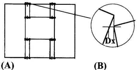
To represent the real behavior of a shear wall more accu- rately, a number of features were introduced to the basic model. First, the pin joints connecting frame members were replaced with spring elements: two linear springs in the vertical and horizontal directions and one linear spring in the rotational direction. The springs were independent each other in terms of compression, tension, shear, and rotation. Initial gaps in the frame joints were not considered in the model. The flexibility of hold-down connections was mod- eled by introducing a tension stiffness of the particular frame joints corresponding to the hold-down stiffness ob- tained from small specimen tests. A t the locations of the hold-down connections, the bottom plate was assumed to be rigidly connected to the foundation. In the analyses ne- glecting slips in hold-down connections, the hold-down stiff- ness was set close to infinity. Constraint by the bearing between adjacent sheathing panels was modeled by unilat- eral constraint equations between the horizontal dis- placements of coincident panel corners. In the case of "compression" the horizontal displacements at the corners were equal. In case of "tension" there was no such con- straint. These conditions were determined within each it- eration at each load increment. Bearing was assigned only to the corners of the panels to minimize the extra computa- tional time needed for this feature. A t the small panels above and underneath openings, the constraints were set between these panel corners and the coincidental nodes, at the adjacent panel edge, which were not necessarily corner nodes, as shown in Fig. 1A. Because of the choice of re- straining only the horizontal degrees of freedom at the
@
(A)
(B)
Fig. 1. Model representing constraint by the bearing between adjacent sheathing panels. A Location of constrained nodal points. B Error
(Dx)
due to the simplified bearing used1400
1200
1000
Z 800
o 600
400
200
0
S
/
/
i
0 2 4 6 8 10 12
Displacement (mm)
Fig. 2. Trilinear approximation of nail properties used for finite ele- ment analyses
panel corners, there is a slight error (Dx) in the contact definition, as the corner points also move in relation to each other in the vertical direction, as shown in Fig. lB. This error, however, is regarded as insignificant for the load case and wall configuration investigated in this study.
Material properties
Poisson's ratio and the modulus of elasticity (MOE) of the frame members were assumed to be 0.2 and 10.0GPa, respectively. For the panel elements, Poisson's ratio, MOE, and the shear modulus were assumed to be 0.5, 5.3, and 0.7GPa, respectively. The nail properties used for the fastener elements was determined by nail joint tests, as performed by Yasumura and Kawai. 7'8 Trilinear approxi- mation, as shown in Fig. 2, was adopted for the analysis. The embedding stiffness of the frame joints and the tension stiffness of the hold-downs were determined by tests per- formed with static compression loading, as shown in Fig. 3. The embedding and hold-down tests were performed with three specimens for each configuration.
-
- l c e m e n t
(A)
I I I !
Fig. 3. Configuration of tests. A Hold-down test. B Embedding tests
to the slip of the joints, the joints were tested in compres- sion instead of tension, as shown in Fig. 3A. The embedding tests were performed with three different configurations made up of one, two, or three studs, as shown in Fig. 3B. The results from the tests were evaluated to find a suitable linear approximation to be implemented in the finite ele- ment model. The approximations of embedding stiffness were 12.8, 21.2, and 23.7MN/m for one, two, and three studs, respectively. The stiffness for the three-stud speci- men was chosen for the model, as the largest forces arises where three studs are mounted together. The hold-down stiffness was determined to be 13.1MN/m.
Preliminary results showed that the effect of lateral slips on the frame joints was moderate. The lateral stiffness of the joints was thus modeled to be rigid in this study. Furthermore, the rotational stiffness in the frame was disre- garded in the analyses. It is assumed that this stiffness is small compared to the stiffness provided by the panels being attached to the frame. The rotational stiffness of the hold-downs might be more significant. However, it is difficult to estimate this stiffness because it depends on the loading direction and the deformation of the framing. Consequently, it was decided not to take this feature into account.
Analyses
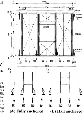
To evaluate the influence of the various features of the model, a plywood-sheathed shear wall of a size correspond- ing to three panels with a window opening in the middle panel, as shown in Fig. 4, was used as the reference object. In the following finite element analyses, each modification was added separately to the basic pin-jointed model to in- vestigate the effect on the results. The model with all new
~ 2 o
~
455f~J
.! ... \
: .-[ U
r
P x
u
-\
i
\ i
\ i \ i
3270 2730 J, - 1365 q
~ I " - II .-"t
/ I " V , -
f i . / , , . . I \ ~.j
\
SPF206
\
/ \.
./ \.
t \
n n
~. / . /
"N.
/ / ' 'x r
\
\ /
\
/ \.
I t '; i ~ / \ I
u
3030
P x
---4
R1 R 2 R 3 R 4
( A ) F u l l y a n c h o r e d
} ~2o 455
u ~ Western
mr Hemlock
4o4
SPF204
HD-B20
R1 R 2 R 3 R 4
( B ) H a l f a n c h o r e d
Fig. 4. Configuration of the wall specimens studied. A Fully anchored shear walls. B Half-anchored shear walls
features was analyzed and compared to the basic model. The analyses were p e r f o r m e d with a conventionally anchored wall and a half-anchored wall. The monitored parameters were the overall load-displacement chara- cteristics, the distribution of vertical reaction forces, and the order in which the nails reached their maximum capacity. Configuration of analyzed shear wall
174
opening the stud packages consisted of two studs above the window opening.
In the wall configuration with hold-downs at both wall ends and opening ends, four hold-downs of HDB-20 were attached with four lag screws 12mm in diameter and 75mm long. In the wall without interior hold-downs, two HDB-20 connectors were used at both wall ends. The bottom plate was attached to the sill and the top plate to the ledger by intermediate bolts in the two outermost joist spacings. In the finite element model the b o t t o m plate was assumed to be pin-jointed at the location of each hold-down and at the positions of the intermediate bolts between the b o t t o m plate and the sill plate. In the model, the position of the latter was adjusted to the closest nodal point to avoid the need of overly dense mesh; this was considered a minor adjustment. The top plate and the ledger were assumed to interact although not completely. The flexural rigidity was assumed to be equal to the sum rigidity of the double top plates and the ledger.
Sensitivity study
In the basic model, all joints connecting frame m e m b e r s were considered to be pin joints. Therefore, the slips in the framing joints were considered during the first analyses. The slip in the tension of the joints was introduced in sev- eral steps. For the first step the tension stiffness was set to zero only at the joints at the window opening, as shown in Fig. 5A. Second, zero stiffness was introduced only in the joints at the top and b o t t o m plates between studs and the top and bottom rails, as shown in Fig. 5B. In the third case, as shown in Fig. 5C, zero stiffness was introduced in all framing joints simultaneously. Some analyses were also per- formed with a tension stiffness corresponding to the initial stiffness seen when pulling out nails. It is assumed, however, that the zero stiffness approach is m o r e accurate because the pulling-out stiffness quickly decreases at m o d e r a t e displacement.
In the following analyses, the framing joints were mod- eled with a compression stiffness corresponding to the em- bedding stiffness of cross-grain compression derived from small specimen experiments accounted for in the previous section. In the model, the same stiffness was introduced at all joints even though the number of studs differed at differ- ent joints. The stiffness was derived from the experiments with three-stud packages. This stiffness is also representa- tive of stud packages of two studs. It is approximately twice the stiffness for embedding when using only one stud. It is
assumed that this is of minor importance, as the largest compression forces occur in the bottom plate at wall ends and openings.
Next, nonrigid hold-downs were evaluated. When intro- ducing flexibility in tension for the hold-down connections, it is, of necessity, combined with flexible framing joints. Constraint by the bearing b e t w e e n adjacent sheathing panels is modeled with pin-jointed framing joints, as in the basic model. In the final analyses all features (i.e., bearing, flexible joints, embedding, and flexible hold-downs) were introduced at the same time.
Results and discussion
Overall wall stiffness
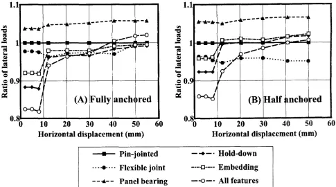
T h e effect of each i n t r o d u c e d f e a t u r e on the load- displacement characteristics for the fully anchored wall is plotted in Fig. 6A. It can be seen that the largest consistent effect is that of the bearing between adjacent sheathing panels. The bearing gives an increase in wall stiffness of about 6%. The other modifications that produce differ- ent flexibilities in the framing joints reduce the stiffness somewhat during the initial phase, by up to 12%. A com- parison of the flexibility in tension at all joints, at only the window rail joints and at the top and bottom plates showed that the effect of flexibility is almost exclusively seen in the joints at the window rails. If all new features are introduced it can be seen that the deviation between the basic model and the modified model is small at larger displacements. The deviation is more pronounced at the beginning of the loading.
The deviation is s o m e w h a t larger for the wall con- figuration without hold-downs at the window opening. T h e difference in deviation, however, is less than 3% b e t w e e n the two wall configurations. In Fig. 6B it can be seen that introduction of a finite embedding stiffness or hold-down stiffness seems to increase the overall stiff- ness. F u r t h e r m o r e , the overall stiffness increases when flexibility in the frame is introduced. This is due to the fact that the frame joints closest to the opening are released in the basic model, whereas they are modeled bilinearly in the modified model. The sudden decrease in capacity that can be seen in the analyses corresponding to flexible joints in regard to all options is due to the fastener formulation (i.e., the negative slope after the maximum load is not included). The capacity of a fastener drops immediately from maxi-
Fig. 5. Location of frame joints where flexibility is introduced. A At opening. B At top and bottom plates. C At all joints
(A)
I
(B)
(c)
m
I,M IJ
O
1.1
0.9
0.8
_ : . . . k . . . . . . - K , & h . - - -
Air " & - K '
1
*"*'4~1
!'
(A) Fully anch~wed
10 20 3 0 40 50
H o r i z o n t a l d i s p l a c e m e n t ( m m )
60
1.1
e~
o
.~ 0.~
0.~
A . . A _ k , . i . . . , g . . . .
- = -
i
hD . . . 1
(B) Half
I I
10 20 30 40 50
mchored
Horizontal displacement (ram)
- P i n - j o i n t e d
. . . . 9 . . . . F l e x i b l e j o i n t
- - , t - - P a n e l b e a r i n g
-- -*-. Hold-down
---o .... Embedding
- - - o - - - A l l f e a t u r e s
Fig. 6. Effect of each modification as well as all of them altogether for fully anchored (A) and half-anchored (B) shear wall
60
Fig. 7. Panel displacement in de- f o r m e d m e s h e s without and with bearing. A Fully a n c h o r e d shear wall B H a l f - a n c h o r e d shear wall. (The displacements are magnified
10 times)
(A) No bearing
Bearing
(B) No bearing
Bearing
mum to zero. This point is reached at an earlier stage in a wall without interior hold-downs than in a fully anchored wall.
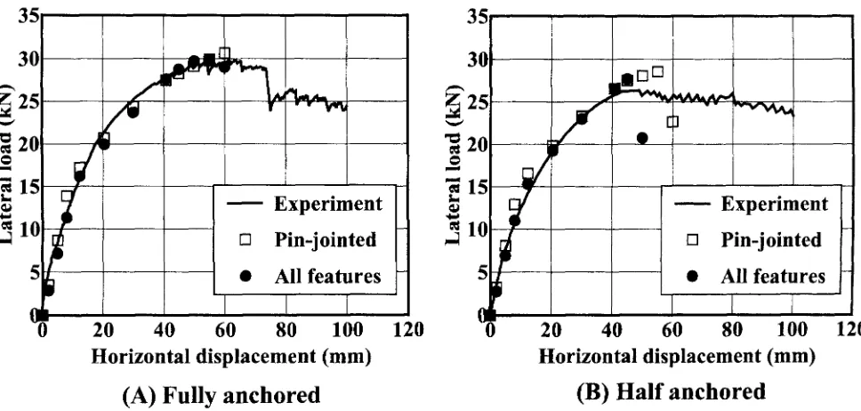
As mentioned previously, the bearing effects increased the wall stiffness. When bearing was introduced, the rota- tion of the panels above and below the window opening increased up to three times for the panel above the opening. The full-size panels were not significantly influenced, as shown in Fig. 7. If the results are considered in relation to the experimental values obtained from a previous study by Nagata and Yasumura, 9 it can be seen that both models are relatively accurate, as shown in Fig. 8. The difference in overall stiffness between the basic model and the modified model, with all new features introduced in the model, is insignificant. The only major difference concerns the maxi- mum load. In the model with flexible joints and bearing, the nails reach their maximum capacity in a slightly different order, with earlier failure at a lower load. This is more pronounced in the wall without interior hold-downs than in the fully anchored wall.
Vertical reaction forces
It is interesting to note that the hold-down forces and the compression forces deviate significantly from the con- ventional approximations used in practical design. This is in accordance with previous studies (e.g., Andreassont~ Commonly, the small walls above and below the opening are generally disregarded, and the wall parts with full-size panels are simply supported, resulting in vertical reaction forces of the same magnitude at all panel ends. In the analy- ses, however, it is evident that the force distribution in a wall with a window opening is quite different, as shown in Table 1. In particular, the reaction forces at the opening are significantly smaller than the predictions based on conven- tional design.
by a b o u t 15%. T h e largest r e d i s t r i b u t i o n c o n c e r n i n g reac- tion forces is o b t a i n e d w h e n i n t r o d u c i n g b e a r i n g b e t w e e n s h e a t h i n g panels. It p r o d u c e s a r e d u c t i o n of a b o u t 33% for the fully a n c h o r e d wall. W h e n all the n e w features are i n t r o d u c e d , the largest d e v i a t i o n is a 30% r e d u c t i o n at the c o m p r e s s i o n side of t h e o p e n i n g . T h e r e d i s t r i b u t i o n is s o m e w h a t m o r e complex for the h a l f - a n c h o r e d wall. W h e n
Table 1. Relative vertical reaction forces at the bottom plate supports obtained in analyses with the basic finite element model
Configuration Reaction force
(%)a
R1 R2 R3 R4 Fully anchored 77 32 32 77 Half-anchored 78 19 - 67 The forces are given in percent of calculated values relative to those in current design principles neglecting the effect of opening
~For explanation of Ri[, R2, R3, and R4 see Fig. 4
applying all modifications, the largest difference is an 18% r e d u c t i o n of the compression force at the opening.
It is e v i d e n t that the d i s t r i b u t i o n of vertical r e a c t i o n forces can be influenced by modifications of the m o d e l de- spite the fact that the overall l o a d - d i s p l a c e m e n t stiffness is unaffected. W h e n c o m p a r i n g the results for stiffness a n d force distribution at a storey drift of 1/60 when all features are i n t r o d u c e d , the overall stiffness is a p p r o x i m a t e l y equal for the basic a n d modified models, whereas the force distribu- tion at the same time by as much as differs 30%. Moreover, the reaction forces deviate significantly from the ones stated by c u r r e n t design methods.
Nail stress pattern
To investigate any changes in nail stress caused by the fea- tures i n t r o d u c e d into the model, the nail failing o r d e r was m o n i t o r e d . T h e order in which the nails reached their maxi-
35
30
25
f
20
20
Horizontal displacement (mm)
(A) F u l l y a n c h o r e d
[]
I
40
60
I
Experiment
Pin-jointed
All features
I
I
80
100
120
120
35
30
e
71 /.
Experiment
1~
[] Pin-jointed
5
9
All features
~0
20
40
60
80
100
Horizontal displacement (mm)
(B) H a l f a n c h o r e d
Fig. 8. Comparison of experimental results with calculation by basic and modified finite element models for fully anchored (A) and half-anchored (B) shear wall
Table 2. Influences of model modifications on the distribution of reaction forces in fully anchored and half-anchored shear walls Feature Fully anchored ~ (kN) Half-anchored (kN)
Px R1 (%) R2 (%) R3 (%) R4 (%) Px R1 (%) R2 (%) R3 (%) R4 (%) Pin jointed 27.46 28.43 (77) -11.73 (32) 11.69 (32) -28.42 (77) 2 6 . 5 2 27.90 (78) -6.85 (19)
Flexible joints 2 6 . 6 5 28.20 (79) -12.88 (36) 13.0 ( 3 6 ) -28.03 (78) 25.23 27.64 (81) -8.67 (26) Bearing 29.06 28.53 (73) -8,27 (21) 8.41 ( 2 1 ) -28.76 (74) 2 8 . 2 9 27.93 (73) -4.52 (12) Flexible 27.02 25.44 (70) -10.74 (30) 9.29 ( 2 6 ) -28.68 (79) 26,93 25.34 (70) 7.76 (21)
hold-downs
Embedding 27.23 28.58 (78) -10.17 (28) 11.42 (31) -26.85 (73) 26,95 28.41 (78) -6.83 (19) All options 27.61 26.19 (70) -8.31 (22) 8.61 ( 2 3 ) -27.18 (73) 2 6 , 5 4 26.02 (73) -5.62 (16)
-24.06 (67) 22.75 (67) -25.21 (66) -29.29 (81) -27.08 (75) -23.33 (65)
The results are given for an apparent shear deformation of 1/60
m u m load capacity was surveyed. The first ten nails to reach m a x i m u m load were evaluated and comparisons were m a d e between analyses. There was a general trend that the num- ber of nails reaching the m a x i m u m load at the same load increment was much larger for the walls with a conventional hold-down configuration than for the walls without interior hold-downs. It is thus c o n c l u d e d that the nail forces are m o r e equally distributed in the fully a n c h o r e d wall. This seems reasonable, as the force distribution ought to be m o r e complex in the perforated wall because of the asymmetrical stiffness at the up-lifting studs.
O u r analyses showed that the nail-failing pattern is sig- nificantly changed when new features are introduced in the model. First, it was n o t e d that the exposure of the nails differs significantly between a wall with hold-downs at both the wall ends and the o p e n i n g and a wall with no hold- downs at the window opening. In the latter case, the main failure takes place in the panel under the window, whereas the m o s t exposed nails are f o u n d at the full-size panels if hold-downs are fully anchored, as shown in Fig. 9. This is due to the fact that the studs at the opening are free to lift in the second case, which increases the d e f o r m a t i o n of the
fasteners at the up-lifting stud. W h e n flexibility in compres- sion is i n t r o d u c e d to take e m b e d d i n g of the f r a m e into account, it can be seen that this gives a m o r e exposed situ- ation for the nails at the first c o m p r e s s i o n stud at the left side of the window opening. W h e n flexibility in tension is introduced in the frame, in both the frame joints and hold- downs, a m o r e severe situation for the nails is created at the up-lifting point of the window opening. This p h e n o m e n o n also occurs when only the joints at the window rails have flexible tension. F o r the wall w i t h o u t h o l d - d o w n s at the o p e n i n g , no t r e n d c o r r e l a t e d with the i n t r o d u c t i o n of the flexibility in tension. This is also true for the effect of the bearing b e t w e e n sheathing panels. A clear trend can be seen for the fully a n c h o r e d walls, however. T h e bearing b e t w e e n the panels increases the stress of the nails at the o u t e r m o s t contact points. W h e n all new features are intro- duced simultaneously in the model, the main observation is that the nail failing o r d e r agrees well for the simple and m o r e advanced models. As m e n t i o n e d previously, this is also true for the overall load-displacement relation of the wall. T h e probable explanation for this similarity, despite the m a n y differences b e t w e e n the models, is that some of
Fig. 9. Nail-failing pattern in vari- ous models. A Fully anchored shear wall. B Half-anchored shear wall
(A) Basic model with fully anchored hold-down
(A) No embedding
E l
(A) Pin-jointed
U_2
_
(A) No panel bearing
(A) Pin-jointed
(A) Embedding
(A) Flexible at opening
(A) Panel bearing
D
(A) All features
(B) No interior hold-down
i
(B) No embedding
(A) Flexible at framing
(B) No panel bearing
I: ,L
(B) Pin-jointed
(B) Embedding
E7
(B) Flexible at hold-down
(B) Panel bearing
the features counteract each other. For instance, the effect of the bearing makes the wall stiffer, whereas the effect of flexible frame joints makes the wall less stiff.
Conclusions
Results from analyses of a discontinuous wall with a win- dow opening show that the effect of constraint by the bear- ing between adjacent sheathing panels and slips in framing joints on the overall stiffness of the wall is limited (less than 10%). A m o n g the various features investigated in this study, bearing between adjacent sheathing panels has a pro- nounced influence on the results. If bearing is introduced, the overall stiffness increases by approximately 6%. The vertical reaction forces decrease by approximately 30% at the interior supports. Because bearing increases the overall stiffness and decreases the reaction forces, it is safe to disre- gard the effect of bearing. Furthermore, it is often desirable to avoid bearing b e t w e e n panels in real construction to prevent buckling of sheathing panels due to moisture variation.
Flexibility in the tension of frame joints and hold-downs is the second most important feature. In this case the mag- nitude of the impact is about 3 % - 1 5 % for wall stiffness and reaction forces. To take flexibility in frame joints into con- sideration, it is sufficient to introduce such flexibility at only the opening rails if the wall is fully anchored. Flexibility in the joints at the top and b o t t o m plates at other positions causes no significant difference. The effect of the flexibility of frame joints, and to some extent the effect of bearing, is m o r e pronounced in the wall without hold-downs at the opening.
When all features are introduced in the model, the differ- ence in overall stiffness is 1% at most. This is due to the fact that some features counteract each other. However, the effect of the vertical reaction forces might still be signifi- cantly influenced by these features. In our analyses, the deviation was about 30% at the interior supports and 8% at the end supports.
If flexibility in joints and bearing between sheathing panels is considered, the nail failing pattern is somewhat more critical. The most exposed nails reach their maximum capacity at a lower load.
Finally, it was noted that the distribution of vertical reac- tion forces deviates significantly from that in conventional design approaches. The forces at interior and end supports might be as low as 20%-70% of the predicted ones. This is also true when using the basic pin-jointed model.
Acknowledgments This study was conducted at Shizuoka University with the support of the Sweden-Japan Foundation. The authors thank the Sweden-Japan Foundation for offering a scholarship to S.A. to undertake this study.
References
1. Filiatrault A (1990) Static and dynamic analysis of timber shear wails. Can J Civil Eng 17:643-651
2. Dolan JD, Foschi RO (1991) Structural analysis for static loads on timber shear walls. J Struct Eng 117:851-861
3. Falk RH, Itani RY (1989) Finite element modeling of wood dia- phragms. J Struct Eng 115:543-559
4. Kazal B, Leichti RJ, Itani RY (1994) Non-linear finite-element model of complite light-frame wood structures. J Struct Eng 120:100-119
5. Tarabia A, Kamiya F (1996) Analytical response of wood shear walls using hysteresis models of nailed joints. Mokuzai Gakkaishi 42:1064-1071
6. Davenne L, Daudeville L, Kawai N, Yasumura M (1997) A nu- merical analysis of shear walls structural performance. In: Proceed- ings of the CIB-Wl8 meeting 19, Canada 19-i5-3, pp 1-10 7. Yasumura M (1999) Static and dynamic performance of wood-
framed shear walls. In: Proceedings of the 1st RILEM Symposium on Timber Engineering, Stockholm, pp 481~490
8. Yasumura M, Kawai N (1998) Estimating seismic performance of wood-framed structures. In: Proceedings of 5th WCTE, vol 2, pp 564-571
9. Nagata M, Yasumura M (2000) Shear strength of wood based shear walls with opening. In: Abstracts of the 50th annual meeting of the Japan Wood Research Society (in Japanese), Kyoto, p 255 10. Andreasson S (2000) Three-dimensional interaction in stabilisa-
tion of multi-storey building systems. Licentiate thesis, Lund Uni- versity, Lund