Author for correspondence:
Volume-7 Issue-1
International Journal of Intellectual Advancements
and Research in Engineering Computations
Implementation of Fast Binary Counters using Symmetric Stacking
V.Marimuthu
1, P.Sukumar
21
PG Scholar Department of Electronics and Communication Engineering, Nandha Engineering
College (Autonomous), Erode.
2
Professor Department of Electronics and Communication Engineering, Nandha Engineering
College (Autonomous), Erode.
ABSTRACT
A new binary counter design is proposed. It uses 3-bit stacking circuits, which group all of the “1” bits together, followed by a novel symmetric method to combine pairs of 3 -bit stacks into 6-bit stacks. The bit stacks are then converted in to binary counts, producing 6:3 counter circuits without xor gates on the critical path. The eliminated xor gates results in faster designs with efficient power and area utilization. In the proposed work “and, or, xor” gates are replaced by 4:1 multiplier to design the 6:3 counter. The proposed counters in existing counter-based on Wallace tree multiplier architectures reduces latency and power consumption for 64 bit multipliers.
Index
term
: Stacking, Power, Area, LatencyINTRODUCTION
In order to combine the partial products efficiently, column compression is commonly used. Many methods have been presented to optimize the performance of the partial product summation, such as the well-known row compression techniques in the Wallace tree or Dadda tree, or the improved architecture. These methods involve using full adders functioning as counters to reduce groups of 3 bits of the same weight to 2 bits of different weight in parallel using a carry-save adder tree. Through several layers of reduction, the number of summands is reduced to two, which are then added using a conventional adder circuit. To achieve higher efficiency, larger numbers of bits of equal weight can be considered. The basic method when dealing with larger numbers of bits is the same: bits in one column are counted, producing fewer bits of different weights. For example, a 7:3 counter
circuit accepts 7 bits of equal weight and counts the number of “1” bits. This count is then output using 3 bits of increasing weight. The 7:3 and 6:3 counter circuits can be constructed using full and half adder. Various recoding schemes are used to reduce the number of partial products. Compressors have been widely used for reduction process which usually contributes the most to the delay, power and area of the multiplier. To achieve a better performance, the use of higher order compressors instead of conventional compressors, e.g. 3:2 compressors, have been considered. The reduction process finally results in a 2-row matrix, and then a high speed adder is used to get the final result from the two rows. Several type of implementation based on the conventional 7:3 architecture is proposed to be used for fast multiplication or multiple addition applications. The proposed 7:3 compressors and the most efficient contender have been simulated using HSPICE 0.25um technology. The results show a
drastic improvement, as will be discussed later. Previously, 3:2 compressors were used to reduce the partial product matrix; each reduces the number of inputs by a factor of 3:2. Thereafter, for the purpose that the compression rate might be increased, other higher order compressors have been developed. This attempt has yielded a faster partial product compression than the use of 3:2 counters [1-3].
Symmetric bit stacking
The proposed 6:3 counter is realized by first stacking all of the input bits such that all of the “1” bits are grouped together. After stacking the input bits, this stack can be converted into a binary count to output the 6-bit count. Small 3-bit stacking circuits are first used to form bit stacks. These 3-bit stacks are then combined to make a 6-3-bit stack using a symmetric technique that adds one extra layer of logic.
Three-Bit Stacking Circuit
Given inputs X0, X1,and X2, a 3-bit stacker
circuit will have three outputs Y0, Y1, and Y2 such
that the number of “1” bits in the outputs is the same as the number of “1” bits in the inputs, but the “1” bits are grouped together to the left followed by the “0” bits. It is clear that the outputs are then formed by
Y0 =X0+X1+X2
Y1 =X0X1+X0X2+X1X2
Y2 =X0X1X2
Namely, the first output will be “1” if any of the inputs is one, the second output will be “1” if any two of the inputs are one, and the last output will be one if all three of the inputs are “1.” The Y1 output is a majority function and can be implemented using one complex CMOS gate. The 3-bit stacking circuit [4-8].
High speed counters
The aim of the proposed counter-based Wallace multiplier is to use only the 7:3 counters along with the full adder and half adder to construct the multiplier. [9, 10]However this would result in more reduction stages as well as the restriction of a generic formula to compute the number of reduction stages for a N-bit multiplier. This issue is solved by incorporating 6:3, 5:3, and 4:3
counters along with the preferred 7:3 counter. We used the 7:3 counter proposed due to its simple and fast circuit. The Boolean equations used to implement these counters are given as follows
Counter
The design of 7:3 counter is extensively studied in the literature and a number of architectures are proposed. The 7:3 counter proposed is selected for the proposed CBW multiplier due to its high speed operation. The Equation gives the boolean functions for Sum, Cout1, and Cout2 for the 7:3 counter [11-15].
Converting bit stack to binary number
In order to implement a 6:3 counter circuit, the 6-bit stack described must be converted to a binary number. For a faster, more efficient count, we can use intermediate values H,I, and K to quickly compute each output bit without needing the bottom layer of stackers. Call the output bits C2,C1,
and s in which C2, C1,Sis the binary representation
of the number of “1” input bits. To compute S, we note that we can easily determine the parity of the outputs from the first layer of 3-bit stackers. Even parity occurs in the zero or two “1” bits appear in X0, X1,and X2. Thus, He and Ie, which indicate
even parity in the H and I bits, are given by He = H0+H1H2
Ie = I0+I1 I2.
As S indicates odd parity over all of the input bits, and because the sum of two numbers with different parities is odd, we can compute B0 as S=He ⊕ Ie
Although this does incur one XOR gate delay, it is not on the critical path. To computeC1, we
noteC1=1 when the count is 2, 3, or 6. Therefore,
there are two cases. First, we need to check if we have at least two but no more than three total inputs. We can use the intermediate H,I, and K vectors for this. To check for at least two inputs we need to see stacks of length two from either top level stacker, or two stacks of length one, which yields H1+I1+H0I0. To check that we do not have
more than three inputs set, we simply need to make sure that none of the K bits are set as the K vector is only set when more than three inputs are “1,” as discussed in Section II. This gives (K0+K1+K2)`
as “1.” We can check this by checking that all three of both the H and I bits are set. As these are bit stacks, we simply check the rightmost bit in the stack for this case, which yields H2I2. Altogether, these yields [16, 18]
C1 = (H1+I1+H0I0)-(K0+K1+K2) +H2I2.
We can easily calculateC2 as it should be set whenever we have at least 4-bit set
C2 = K0+K1+K2.
The final 6:3 counter circuit can be constructed as shown in Fig. 4. Using larger CMOS gates, the critical path delay is reduced to seven basic gates. As there are no XOR gates on the critical path, this 6:3 counter outperforms existing designs [17,19].One drawback of this design is an increase in wiring complexity: we see from that the symmetric approach necessitates signals crossing after the first layer of stackers, while traditional counters do not have as many crossing paths.
EXISTING SYSTEM
COUNTER SIMULATION
Fig.1.A 6:3 Counters based on Symmetric Stacking
The 6:3 counter design was built as a standard CMOS design and simulated using spectra, using the ON semiconductor C5 0.5-μm process (formerly AMI06). For comparison, a 6:3 counter design was implemented using standard CMOS full adders as in Fig. 1. The parallel counter was converted to a 6:3 counter and simulated as well. It has a critical path delay of 3∆XOR+2 basic gates. The mux-based counter design was also simulated. It has a critical path delay of 1∆ XOR+3∆ MUX. Two of the muxes on the crucial path can be implemented with trans-mission gate logic which is slightly faster. The proposed 6:3 counter has no XOR gates or muxes on its critical path. It has a
XOR gates on its critical path, it operates nearly 30% faster than all other counter designs. Thus, this novel method of counting via bit stacking allows construction of a counter for a substantial performance increase without increasing power consumption [20-22].
PROPOSED SYSTEM
In order to combine the partial products efficiently, column compression is commonly used. Many methods have been presented to optimize the performance of the partial product summation, such as the well-known row compression techniques in the Wallace tree or Dadda tree, or the improved architecture in new design technique for column compression multipliers. These methods involve using full adders functioning as counters to reduce groups of 3 bits of the same weight to 2 bits of different
weight in parallel using a carry-save adder tree. Through several layers of reduction, the number of summands is reduced to two, which are then added using a conventional adder circuit. To achieve higher efficiency, larger numbers of bits of equal weight can be considered. [23]The basic method when dealing with larger numbers of bits is the same: bits in one column are counted, producing fewer bits of different weights. For example, a 7:3 counter circuit accepts 7 bits of equal weight and counts the number of “1” bits. This count is then output using 3 bits of increasing weight. The 7:3 and 6:3 counter circuits can be constructed using full and half adders. Much of the delay in these counter circuits is due to the chains of adder on the critical path. Therefore, much faster parallel counter based architecture needed to reduce delay. A parallel 7:3 counter used to design a high speed counter-based Wallace tree multiplier.
TABLE 1
MULTIPLIER SIMULATION RESULTS
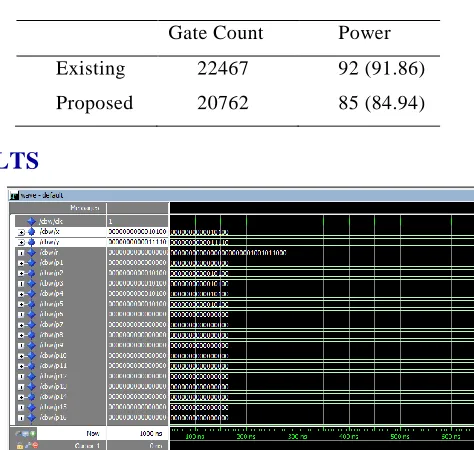
SIMULATION RESULTS
Fig 2. Simulation result for counter based Wallace tree multiplier
CONCLUSION
In this brief, a new binary counter based on a novel symmetric bit stacking approach is proposed. We showed that this counting method can be used to implement counter based Wallace tree multiplier, which can be used in any binary
multiplier circuit to add the partial products. this bit stacking technique achieve higher speed than other higher order counter designs while We demonstrated reducing power consumption. This is due to the lack of XOR gates and multiplexers on the critical path.
Gate Count Power
Existing 22467 92 (91.86)
REFERENCE
[1]. C. S. Wallace, “A suggestion for a fast multiplier,”IEEE Trans. Electron. Comput. 13(1), 1964, 14–17. [2]. L. Dadda, “Some schemes for parallel multipliers,” Alta Freq., 34, 1965, 349–356.
[3]. Z. Wang, G. A. Jullien, and W. C. Miller, “A new design technique for column compression multipliers,”IEEE Trans. Comput., 44(8), 1995, 962–970.
[4]. M. Mehta, V. Parmar, and E. Swartzlander, “High-speed multiplier design using multi-input counter and compressor circuits,” inProc. 10th IEEE Symp. Comput. Arithmetic, 1991, 43–50.
[5]. S. Asif and Y. Kong, “Design of an algorithmic wallace multiplier using high speed counters,” inProc. IEEE Comput. Eng. Syst. (ICCES),2015, 133–138.
[6]. S. Veeramachaneni, L. Avinash, M. Krishna, and M. B. Srinivas, “Novel architectures for efficient (m, n) parallel counters,” inProc. 17th ACM Great Lakes Symp. VLSI, 2007, 188–191.
[7]. S. Veeramachaneni, K. M. Krishna, L. Avinash, S. R. Puppala, and M.B. Srinivas, “Novel architectures for high-speed and low-power 3-2, 4-2 and 5-2 compressors,” inProc. 20th Int. Conf. VLSI Design Held Jointly 6th Int. Conf. Embedded Syst. (VLSID), 2007,324 –329.
[8]. V. G. Oklobdzija, D. Villeger, and S. S. Liu, “A method for speed opti-mized partial product reduction and generation of fast parallel multipliers using an algorithmic approach,”IEEE Trans. Comput., vol. 45(1), 1996, 294–306.
[9]. S. Asif and Y. Kong, “Analysis of different architectures of counter based Wallace multipliers,” in Proc. 10th Int. Conf. Comput. Eng. Syst. (ICCES), 2015, 139–144.
[10]. J. Gu and C.-H. Chang, “Low voltage, low power (5:2) compressor cell for fast arithmetic circuits,” in Proc. IEEE Int. Conf. Acoust., Speech, Signal Process. (ICASSP), 2, 2003, 661–664.
[11]. K. Prasad and K. K. Parhi, “Low-power 4-2 and 5-2 compressors,” in Proc. Conf. Rec. 35th Asilomar Conf. Signals, Syst. Comput.,1, 2001, 129–133.
[12]. I. Koren, Computer Arithmetic Algorithms, 2nd ed. Natick, MA, USA: A. K. Peters, 2002.
[13]. M. Rouholamini, O. Kavehie, A.-P. Mirbaha, S. J. Jasbi, and K. Navi, “A new design for 7:2 compressors,” in Proc. IEEE/ACS Int. Conf. Comput. Syst. Appl., 2007, 474–478.
[14]. A. Dandapat, S. Ghosal, P. Sarkar, and D. Mukhopadhyay, “A 1.2-ns 16 ×16-bit binary multiplier using high speed compressors,” Int. J. Elect. Electron. Eng., 4(3), 2010, 234–239.
[15]. D. Radhakrishnan, “Low-voltage low-power CMOS full adder,” IEE Proc.-Circuits, Devices Syst., vol. 148(1), 2001, 19–24.
[16]. S.-F. Hsiao, M.-R. Jiang, and J.-S. Yeh, “Design of high-speed low-power 3-2 counter and 4-2 compressor for fast multipliers,”Electron. Lett., 34( 4), 1998, 341–343.
[17]. T Maheswari, P Sukumar „Error Detection and Correction in SRAM Cell Using Decimal Matrix Code‟ IOSR Journal of VLSI and Signal Processing (IOSR-JVSP) Publication date 5(1), 2015, 09-14.
[18]. P.Sukumar M.Kangavalli “Asynchronous Transfer Mode Implementation Using Z-T CAM” International Journal of Engineering Research-Online 3(2), 2015, 155 – 162.
[19]. P.S.Tamilselvi, P.Sukumar “Power Reduction for Sequential Circuit using Merge Flip -Flop Technique” International Journal of Emerging Technology and Advanced Engineering (IJETAE), 4(2), 2014, 926-932.
[20]. P.Sukumar K.Sabeha “Highly Secured System to Find the Improper Impression of Fingerprints in Hostel” International Journal for Scientific Research & Development Volume 3(11), 2016,6.
[21]. P.Uma Devi,P. Sukumar “Low Energy Asynchronous CAM Based On Reordered Overlapped Search Mechanism” The International Journal Of Science & Techno ledge, 3(3), 2015, 74 – 80.
[22]. P.Sukumar K.Sabeha “Highly Secured Indoor Outdoor Localization for E- Hostel Management” journal of Network Communications and Emerging Technologies (JNCET) Vo lume 5(1), 2015, 30-34.