A Fuzzy Based Distributed Algorithm
for Maintaining Connected Network
Topology in Mobile Ad-Hoc Networks
Considering Freeway Mobility Model
Jishan Mehedi
1and Mrinal Kanti Naskar
21Department of Electronics and Communication Engineering, National Institute of Technology, Silchar, Assam, India 2Advanced Digital and Embedded Systems Lab, Department of Electronics and Telecommunication Engineering,
Jadavpur University, Kolkata, India
Mobile Ad-Hoc Networks(MANETs)present real-time embedded system that is being used in a wide variety of applications where traditional networking infrastructure is practically infeasible. The highly dynamic character of a Mobile Ad-Hoc Network(MANET)poses significant challenges on network communications. Previous work on MANET has resulted in numerous routing protocols aiming to maintain network connectivity among the ac-tive nodes. This paper presents a fuzzy-based distributed algorithm to maintain connected MANET considering freeway mobility model. According to the algorithm, each node will control itself in a way that it can maintain its connectivity with other nodes. In this approach each node is enabled with a Global Positioning System(GPS) receiver. Through GPS each and every node is getting its position and velocity. After getting the information all the nodes in a network transmit their position and velocity information periodically. Obtaining information from all other nodes, each node will decide its own velocity to maintain connectivity. Moreover, faults to a particular node have also been considered in this algorithm. Results obtained through simulation studies show the effectiveness of the proposed algorithm.
Keywords: ad-hoc networks, connectivity, fuzzy logic, freeway mobility model, distributed algorithm
1. Introduction
A Mobile Ad-Hoc Network(MANET)is a net-work of autonomous mobile nodes able to com-municate over wireless links without the help of any fixed infrastructure[1, 2, 3, 12]. MANET is projected to play a vital role when there is little or no communication infrastructure or the exist-ing infrastructure is expensive or inconvenient
came into picture. All the nodes are mobile in a MANET and movement pattern of the nodes may be different, depending on the application of a MANET. Researchers have developed dif-ferent mobility models, depending on difdif-ferent movement patterns of the nodes, namely Pur-sue Mobility Model[17, 18], Nomadic Commu-nity Mobility Model [17, 18], Freeway Mobil-ity Model[18], Group Mobility Model[17, 18], Manhattan Mobility Model [16, 18], Random Gauss-Markov Model[17]etc. It is a challeng-ing task to maintain a connected network durchalleng-ing the movement of a MANET. Since mobility pat-tern is different for different mobility models, connectivity maintenance algorithm will also be different for different mobility models.
Two widely accepted approaches for topology management are centralized and distributed[1, 3]. Few centralized connectivity management algorithms [1, 3, 5] tried to maintain the over-all topology of the network and at the same time eliminated the risk of detachment of a node due to its mobility. But these algorithms were affected due to the failure of the Coor-dinator/Leader. Few distributed schemes[6, 7] were also proposed in the literature. But none of them considered the fault tolerance while main-taining connectivity.
In this paper, a fuzzy-based distributed fault tolerance algorithm for connectivity manage-ment is proposed considering freeway mobil-ity model. Fuzzy logic has several properties that qualify it as an effective tool for MANET. Firstly, it can be implemented on limited hard-ware and is computationally fast. Secondly, it handles unreliable and imprecise information, offering a robust solution to decision fusion un-der uncertainty. Thirdly, fuzzy-based method-ology substantially reduces the design and de-velopment time in control systems. Fourthly, fuzzy logic control is capable of making real time decisions, even with incomplete informa-tion. Conventional control systems rely on an accurate representation of the environment which generally does not exist in reality. Fifthly, fuzzy logic systems can manipulate the linguis-tic rules in a natural way. Finally, fuzzy con-trollers handle non-linear systems better when compared to conventional approaches [25]. To get these advantages, fuzzy-based distributed approach is chosen for connectivity manage-ment.
This algorithm not only ensures the connectiv-ity of the nodes when there is no fault, but also restores connectivity if it is broken due to faulty nodes during movement of the networks. The remainder of the paper is organized as fol-lows: Section 2 reviews related research works on MANET. Freeway Mobility Model is de-scribed in Section 3. In Section 4 network model used in the proposed algorithm is dis-cussed. Section 5 presents the proposed fuzzy-based algorithm. Simulation results of the pro-posed algorithm and a comparative study are re-ported in Section 6 and Section 7 respectively. Finally, Section 8 concludes the paper.
2. Related Works
based on either the mobility of a single node or a group of nodes. In group mobility models, the mobile nodes movement decision depends upon other mobile nodes in the group and needs topol-ogy management. Several mobility models for wireless nodes are discussed by J. Boudec J.-Y. L. Boudec and M. Vojnovi´c in[18]. Maintain-ing a connected network durMaintain-ing movement of the nodes is a challenging task, especially when the network topology is changing continuously. If the networks do not remain connected, then none of the routing protocols will be able to find a path for communication. Few centralized and distributed algorithms were proposed for maintaining connected network during move-ment. S. S. Basu and A. Chaudhari[1]discussed one scheme for maintaining connectivity of the MANET nodes. In this scheme, elected ‘Co-ordinator’ will control the movements of other nodes through ‘HELLO’ and ‘control’ message communications. They modified their previ-ous algorithm incorporating nodes with GPS receiver in[3]. Due to the use of GPS receiver, exact location of a node is known to the coor-dinator, and, as a result, mobility of the net-work is improved in this scheme. S. Samanta, S. S. Ray, S. SenGupta, M. K. Naskar [5] dis-cussed a probabilistic approach for maintain-ing connectivity in a centralized manner. Jin-shan Liu and Francoise Sailhan[19]presented a group management technique for Mobile Ad-Hoc Networks. However, in the centralized algorithms considered so far, the workload on the coordinator is immense. If the coordinator fails, then the whole network will fail. Lo-cation dependent experiences sharing between the nodes in MANET are discussed by Kih-wan Kim, Ying Cai and Wallapak Tavanapong [20]. This gives the idea of distributed move-ment control of the nodes for maintaining con-nected networks during movement. Avik Ray, Kanad Basu, Samir Biswas, Mrinal K. Naskar [7]proposed one distributed connectivity main-tenance algorithm. Another distributed scheme is proposed in[6]. These schemes totally elim-inate the concept of coordinator and the work-load of the network is distributed among all the nodes. Main problem with the above schemes is that sometimes, in emergencies, there may be rapid velocity changes in the nodes. To over-come this problem, fuzzy logic is introduced for movement control. E. Natsheh, A. B. Jan-tan, S. Khatun and S. Subramaniam [21] have
discussed fuzzy-based approach for finding out the route for local connectivity of nodes, but in this approach there is no guarantee that the whole network will be always connected. This paper proposes fuzzy-based distributed gorithm for Freeway mobility model. This al-gorithm guarantees connectivity of the network even if it is broken due to the failure of a node.
3. Freeway Mobility Model
Figure 1.Maps for freeway mobility model.
same freeway are within the safe distance, the velocity of the following node cannot exceed the velocity of the preceding node. Numer-ous applications exist for this type of mobility model. This model emulates the motion behav-ior of mobile nodes on a freeway. This mobility pattern may have application in scanning and searching purposes e.g. anti-personal mines de-activation robots and can be used in exchanging traffic status or tracking a vehicle on a freeway and for transportation convoy. One particular useful application of a MANET is a Vehicu-lar Ad-hoc Network(VANET), where vehicles represent mobile nodes that communicate us-ing their onboard devices amongst ships where no infrastructure is available which helps to ex-change information regarding pirates, weather, threat, emergency or critical condition.
4. Network Formation
In this paper, MANET is modeled considering freeway mobility model for some specific appli-cations like convoy of soldiers moving towards battlefield or rescue team in different vehicles moving towards same destination in the same road. In these cases, one vehicle can exchange its information through the onboard MANET nodes. To model the network for those appli-cations, this paper defines some useful param-eters along with some assumptions. A number of lemmas along with their proofs are given in the next section to choose the values of the pa-rameters.
In this paper, a fuzzy-based distributed algo-rithm is proposed for maintaining a connected
network during the entire time of the movement of the nodes. Freeway mobility model has been considered assuming uni-directional movement of the nodes in this algorithm. The network model is shown in Figure 2. Here each node will try to maintain connectivity with its front node only and, as a result, the network will be-come connected. Here ‘y’ is the front node and ‘u’ is the rear node.
Figure 2.Network model.
4.1. Parameter Definitions and Their Notations
Maximum Communication Range (Rmax): the
maximum range of distance over which two nodes can communicate among themselves is called maximum communication range and it is denoted by ‘Rmax’.
Threshold Distance (Rth): Initially, each node
will have to maintain distance less than or equal to a specific distance from its front node. This distance is called threshold distance and it is de-noted by ‘Rth’ where maximum communication
range ‘Rmax’ is greater than threshold distance,
‘Rth’ as shown in Figure 3.
Beacon Interval (T): The time interval after which the nodes transmit their information pe-riodically is called beacon interval which is de-noted by ‘T’. Beacon interval (T) is chosen (Rmax−Rth)/VmaxwhereVmaxis the maximum
velocity of the node. The proof for choice of the beacon interval is shown in Lemma 4.3.1.
4.2. Network Setting
i) Each node has a unique identification num-ber.
ii) All nodes are enabled with GPS trans-recei-vers which can furnish the current position and velocity of each node.
iii)All the nodes have a predefined maximum velocity,Vmax.
iv)At the beginning, the network is connected and all the nodes can communicate with each other in single hop.
v) Each node also acts as router and one routing table which keeps the record of all the single hop connected nodes with their positional information.
4.3. Lemmas
4.3.1. Lemma for choosing beacon interval
If maximum communication range is ‘Rmax’
and threshold distance is ‘Rth’, where Rmax >
Rth, maximum preferred velocity ‘Vmax’, then
beacon interval must be less than or equal to (Rmax −Rth)/Vmax, and there is no chance for
the nodes to go out of the communication range.
Proof: Maximum preferred velocity of a node is Vmax. So the maximum possible relative
ve-locity between two nodes is Vmax. Hence, the
maximum relative distance traveled in a bea-con interval isTVmax. Since initially maximum
separation between two nodes may be ‘Rth’, a
connected node cannot become disconnected if,
T·Vmax ≤(Rmax −Rth) (1)
or,
T ≤(Rmax−Rth)/Vmax. (2)
4.3.2. Lemma for choosing threshold distance, ‘Rth’, maximum communication range,
‘Rmax’ and critical velocity, ‘Vc’
If maximumRthamount of spacing between two
nodes is allowed when there is no fault, and if critical velocity Vc = Vmax and 3Rth ≤ 2Rmax
where Rmax is the maximum communication
range, then it is possible to recover connectivity within one beacon interval, even after connec-tivity is broken due to a faulty node.
Proof: The aim is to restore connectivity within one beacon interval. According to the algo-rithm, if there is no fault, all the nodes will maintain a distance less than or equal to Rth
from their respective front nodes. So the worst case scenario before any fault to occur at node 3 is illustrated in Figure 4.
Figure 4.Showing the worst case separation.
It is clear from Figure 4 that in the worst case the distance between node 1 and node 2 is Rth
and the distance between node 2 and node 4 is 2Rth. In this case, according to the
algo-rithm, node 2 will rush with critical velocity (Vc)towards node 4 and node 4 will stop itself.
So after one beacon interval distance between node 1 and node 2 will be (Vc×T +Rth)and
the distance between node 2 and node 4 will be (2Rth−Vc×T). Hence, the restoration of
con-nectivity is possible within one beacon interval if and only if
Vc×T+Rth ≤Rmax (3)
and
(2Rth−Vc×T)≤ Rmax. (4)
Now, ifT is replaced in equation 3 using equa-tion 2, then
Vc ≤Vmax
Again, ifT andVcare replaced in equation 4,
2Rth−Vmax·(Rmax−Rth)/Vmax ≤Rmax (5)
or,
5. Proposed Algorithm
In a centralized system, all the control overhead is with the central administrator or coordina-tor. But in a distributed system[7, 24], control overhead is shared by all the nodes. So the dis-tributed system becomes faster than centralized one. Moreover, in the centralized system, if the administrator or coordinator fails, then the whole system collapses.
Global Positioning System (GPS) [25, 27] re-ceiver is used to get the positional data of a location from satellite. A minimum of three satellite links are required for the module to get the valid data. Here the GPS module tracks up to 12 satellites. The module provides current time, date, speed, longitude, latitude, and altitude. It also provides travel direction. This paper con-siders that the module has ±3 meter position accuracy. Clock synchronization is done using GPS time.
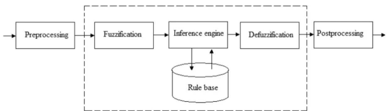
A fuzzy controller executes three basic steps: fuzzification, inference and defuzzification. Dur-ing fuzzification, the numeric input values are mapped to fuzzy sets by applying the member-ship functions. Based on the fuzzified inputs, the controller infers through its IF – THEN rules and produces an aggregated fuzzy output. The final control action is derived by defuzzifying this aggregated fuzzy output.
5.1. Fuzzy Logic Control and Its Expert Knowledge Representation
The model of fuzzy logic control consists of a fuzzifier, fuzzy rules, fuzzy inference engine,
and a defuzzifier. There are specific compo-nents characteristic of a fuzzy controller to sup-port a design procedure. The controller is be-tween a preprocessing block and a post pro-cessing block, as shown in the block diagram in Figure 5.
Here, the objective is to control the movement of each node by itself. Since, this paper pro-poses an algorithm for maintaining connectivity considering freeway mobility model, it is rea-sonable to decompose the problem into three independent controllers corresponding to three different types nodes – front node, rear node and other nodes, with the benefit of simplifying the design and tuning. There are slight differ-ences in the basic structure of the three con-trollers depending on the input variables. The fuzzy controllers follow the design methodol-ogy proposed by Mamdani[28]. The controller is designed with following considerations: • Inputs: the distance from the front node
(Df), distance from the behind node (Db), velocity of the front node(Vf)and velocity
of the behind node(Vb)as input variables.
• Fuzzy sets: For an increased control granu-larity, three fuzzy sets are designed for dis-tances, namely S (Small), M (Medium), L (Large)and Low(L), Medium(M)and High (H)for velocities.
• Membership functions. To leverage the com-putational effort, triangular membership func-tions are used.
• Rule-based inference: the max-min fuzzy inference method is used.
• Output: Output variable is the velocity of a node for the next beacon interval. The con-troller output is decided by defuzzifying the
aggregated inference result using weighted average method[28]. The weighted average method is formed by weighting each mem-bership function in the output by its respec-tive maximum membership value. The cor-responding algebraic expression is given in equation 7. Whereμi(x)is the membership
value,ciis the weight andx¯is the defuzzified
crisp value.
¯ x=
iμi(x)·ci
iμi(x) (7)
The membership functions developed and their corresponding linguistic states are rep-resented in Figure 6a and Figure 6b respec-tively.
Figure 6a.Fuzzy set for fuzzy variable, distance.
Figure 6b.Fuzzy set for fuzzy variable, velocity.
Distance(Db)
Velocity(Vb) S M L
L H L L
M H M L
H H H M
Table 1.Rule Base-1.
Distance(Df)
Velocity(Vf) S M L
L L M H
M L M H
H M H H
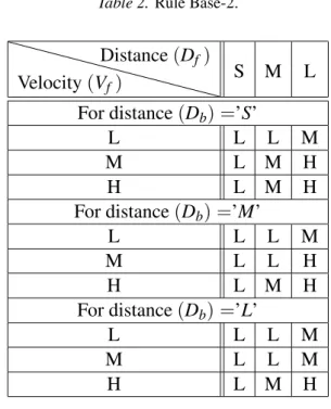
Table 2.Rule Base-2.
Distance(Df)
Velocity(Vf) S M L
For distance(Db) =’S’
L L L M
M L M H
H L M H
For distance(Db) =’M’
L L L M
M L L H
H L M H
For distance(Db) =’L’
L L L M
M L L M
H L M H
Table 3.Rule Base-3.
In this scheme, three different rule bases, de-pending on the index of the node, have been considered. Rule Base-1 is for front node, Rule Base-2 is for rear node and Rule Base-3 is for all other nodes.
and the associated membership functions. The first step in fuzzy inference is to map the crisp inputs to the corresponding linguistic variables through the use of membership functions. This step is referred to as fuzzification. Considering the example in Figure 6a, a measured distance value 4 kilometers is fuzzified as 0.7692 Small and 0.0667 Medium. Often, in fuzzy decision and control systems, the current measured in-puts are fuzzified and taken into account in the inference.
Rule Base: Fuzzy systems are fundamentally
based on IF-THEN rules applied over the fuzzi-fied inputs. Depending on the system to be de-signed, the rule base is constructed from expert knowledge, input-output data, or a combination of the two. The rules have the following format:
IF x1is A1AND x2is A2AND. . .xnis An
THEN y is B,
where xi are input variables with their fuzzy
sets Ai and y is the output variable with the
corresponding fuzzy set B. Considering node movement algorithm, an example of such a rule would be:
IF distance from the front node (Df) is Small
AND distance from the behind node (Db) is Small AND velocity of the front node (Vf) is
Medium THEN velocity for the next beacon interval is Small
Inference: In the inference step, each rule is interpreted as a fuzzy implication and the re-sults of the rules are combined to produce an aggregate fuzzy output. Two of the most fre-quently used methods for implication and rule connection are max-min and sum-product[28]. The max-min fuzzy inference for the movement control of the front, discussed in the following section is considered. For example, the two in-put variables – distance from the behind node (Db), and velocity of the behind node (Vb)
– have measured values of 4 kilometers/hour and 27 kilometers/hour. The input distance from the behind node(Db)is fuzzified through
three membership functions: Small, Medium and Large, using Figure 6a and the input veloc-ity of the behind node(Vb)is fuzzified through
three membership functions: Small, Medium and Large, using Figure 6b. The rule base, as shown in Table 1, consists of 9 rules analyz-ing the fuzzified distance from the behind node
(Db)and velocity of the behind node(Vb)
val-ues. The measured distance from the behind node (Db) value, 4 kilometers/hour, is
fuzzi-fied as 0.7692 Small and 0.0667 Medium. Sim-ilarly, velocity of the behind node (Vb) value,
27 kilometers/hour, is fuzzified as 0.8 Medium. So these fuzzy variables will fire two IF THEN rules. In each rule, the minimum membership value between the two variables is selected and used to trigger the level of the output variable. For example, whenDbis Small(0.7692)AND
Vb is Medium (0.8), then velocity for the next
beacon interval will be Large (0.7692). Here the minimum of the membership values(0.7692 and 0.8)is considered. Similarly, for the second case, whenDbis Medium(0.0667)ANDVbis
Medium(0.8), then velocity for the next beacon interval will be Medium(0.0667). Now, when these two rules are combined, then maximum valued membership value will be considered. For the above example, inference engine will produce velocity for the next beacon interval as Large(0.7692).
Defuzzification: The final step is to defuzzify the aggregated output back to a crisp number that can be used for making decisions or tak-ing control actions. Possible defuzzification methods include: centroid method, largest of maximum(LOM), mean of maximum(MOM), weighted average method etc [28]. For each of the defuzzification methods, crisp value of the output variable is calculated using the cor-responding equations. The weighted average method is formed by weighting each member-ship function in the output by its respective max-imum membership value. The algebraic expres-sion is given in equation 7. If the above example is considered and the weighted average method is used, then the crisp value of output velocity for the next beacon interval is 46.1043 kilome-ters/hour.
5.2. Formal Representation of the Algorithm
three different movement schemes: i) move-ment algorithm for the front node, ii)movement algorithm for the rear node and iii)movement algorithm for all the nodes other than front and rear nodes. In the following subsections these three schemes are presented formally, with nec-essary comments. It is assumed that all the nodes broadcast their velocity and positional in-formation in every beacon interval.
Few notations used in the algorithms are: Nf: front node
Nb: rear node
Nf−i: i-th behind node with respect to the
front node
Nb+i: i-th front node with respect to the rear node
Ni: i-th Node
I(Nf−i): position and velocity information of
the i-th behind node with respect to front node.
I(Nb+i): position and velocity information of
the i-th front node node with respect to the rear node.
I(Ni+1): position and velocity information of the(i+1)-th node.
I(Ni−1): position and velocity information of the(i-1)-th node.
Vc: Critical Velocity
Figure 7.Network representation.
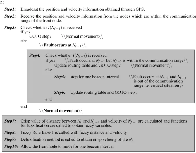
5.2.1. Movement algorithm for front node
Begin:
Step1: Broadcast the position and velocity information obtained through GPS.
Step2: Receive the position and velocity information from the nodes which are within the communication range of the front node.
Step3: Check whetherI(Nf−1)is received
if yes
GOTO step7 \\Normal movement\\
else
\\Fault occurs atNf−1\\
Step4: Check whetherI(Nf−2)is received
if yes \\Fault occurs atNf−1butNf−2is within the communication range\\
Update routing table and GOTO step7 \\Normal movement\\
else
Step5: stop for one beacon interval \\Fault occurs atNf−1andNf−2
is out of the communication range i.e. critical situation\\
Step6: Update routing table and GOTO step 1 end
end
\\Normal movement\\
Step7: Crisp value of distance betweenNf andNf−1and velocity ofNf−1are calculated and functions
for fuzzification are called to obtain fuzzy variables.
Step8: Fuzzy Rule Base-1 is called with fuzzy distance and velocity
Step9: Defuzification method is called to obtain crisp velocity of theNf Step10: Allow the front node to move for one beacon interval
5.2.2. Movement algorithm for rear node
Begin:
Step1: Broadcast the position and velocity information obtained through GPS.
Step2: Receive the position and velocity information from the nodes which are within the communication range of the rear node.
Step3: Check whetherI(Nb+1)is received
if yes
GOTO step7 \\Normal movement\\
else
\\Fault occurs atNb+1\\
Step4: Check whetherI(Nb+2)is received
if yes \\Fault occurs atNb+1butNb+2is within the communication range\\
Update routing table and GOTO step7 else
Step5: rush withVcfor one beacon interval
\\Fault occurs atNb+1andNb+2is out of the communication
range i.e. critical situation\\
Step6: Update routing table and GOTO step 1 end
end
\\Normal movement\\
Step7: Crisp value of distance betweenNbandNb+1and velocity ofNb+1are calculated and the functions
for fuzzification are called to obtain fuzzy variables.
Step8: Fuzzy Rule Base-2 is called with fuzzy distance and velocity
Step9: Defuzification method is called to obtain crisp velocity of theNb Step10: Allow the rear node to move for one beacon interval
5.2.3. Movement algorithm for the nodes other than front and rear nodes
Begin:
Step1: Broadcast the position and velocity information obtained through GPS.
Step2: Receive the position and velocity information from the nodes which are within the communication range of the node in consideration.
Step3: Check whetherI(Ni+1)andI(Ni−1)are received
If both are yes
GOTO step13 \\Normal movement\\
else \\Fault Detected\\
ifI(Ni−1)is not received butI(Ni+1)is received
\\After fault detected at behind node\\
Step4: Check whetherNi−1isNb
if yes, follow the algorithm for rear node \\fault occurs at rear node\\
else
Step5: Check whetherI(Ni−2)is received
if yes
update routing table and GOTO step13 \\Normal movement\\
else \\Fault occurs atNi−1andNi−2is out of the
communication range i.e. the critical situation\\
Step6: Stop for one beacon interval end
end
end
ifI(Ni+1)is not received
\\After fault detected at front node\\
Step7: Check whetherNi+1isNf
if yes, follow the algorithm for front node \\fault occurs at front node\\
else
Step8: Check whetherI(Ni+2)is received
ifI(Nn+2)is received \\Fault occurs atNn+1butNn+2is within
the communication range\\
Update routing table and GOTO step13 \\Normal movement\\
else
Step9: rush withVcfor one beacon interval
\\Fault occurs atNn+1andNn+2is out of the
communication range i.e. critical situation\\
end end
End
Step10: Update routing table
Step11: GOTO step1 End
\\Normal movement\\
Step12: Crisp value of distance betweenNiandNi−1, distance betweenNiandNi+1,velocity ofNn+1
are calculated and function for fuzzification is called to obtain fuzzy variable.
Step13: Fuzzy Rule Base-3 is called with fuzzy distances and velocity
Step14: Defuzification method is called to obtain crisp velocity of theNi Step15: Allow the node to move for one beacon interval
6. Simulation Result
To evaluate the effectiveness of our proposed algorithm in maintaining the connectivity of a MANET, number of simulations using MAT-LAB in Windows environment have been per-formed. The simulator was designed for any number of nodes and the simulation of the al-gorithm for different number of nodes and sim-ulation time ranging from 1 hr to 20 hr has been performed. For simulation of these three sample networks the following system parame-ters: maximum communication range ‘Rmax’=
15 Km, maximum allowable preferred velocity ‘Vmax’=60 Km/hr, threshold distance ‘Rth’=
10 Km are considered. So, the beacon interval is(15−10)/60 i.e. 5 minutes.
6.1. Sample Network I
The network is of ten nodes and their initial coordinates are (−3,1),(0,0),(10,0),(15,0), (23,0),(25,2),(27,−1),(31,3),(33,−2)and (35,0)respectively. Initial network is shown in Figure 8. For this network, simulation is car-ried out for 300 minutes. The distances between each pair of nodes are plotted in Figures 9 and 10 during the movement of the network.
Figure 8.Showing initial network for sample I.
Distance between each pair of nodes is plotted in Figure 9 before the occurring fault and in Figure 10 after the fault. From the above plot it is observed that the fault occurred at node no. 8 at 5thbeacon interval. But the connectivity is always maintained.
Figure 9.Showing the distance between each pair of nodes for sample network I before fault to node 8.
Figure 10.Showing the distance between each pair of nodes for sample network I after fault to node 8.
6.2. Sample Network II
The network is of twelve nodes and their initial coordinates are(−1,0),(4,0),(10,0),(17,0), (19,1),(25,2),(30,0),(34,2),(36,3),(39,3),
(46,3), and(50,2)respectively. Initial network is shown in Figure 11. In this network, two more nodes have been included and the simula-tion is again carried out for 300 minutes. During movement of the networks, separation between each pair of nodes is plotted in Figure 12.
Figure 12.Showing the distance between each pair of nodes for sample network II.
From the above graph it is clear that connectiv-ity of each pair of nodes is maintained for the entire time of the movement of the networks. In this simulation no fault occurred to a node.
6.3. Sample Network III
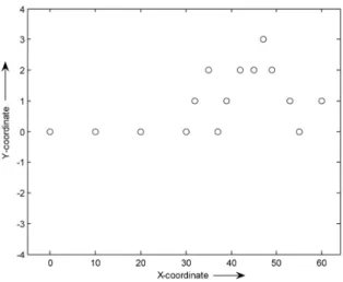
The network is of fifteen nodes and their initial coordinates are (0,0), (10,0), (20,0), (30,0) and (32,1), (35,2), (37,0), (39,1), (42,2), (45,2),(47,3),(49,2),(53,1),(55,0),(60,1)
Figure 13.Showing the initial network for sample network III.
Figure 14.Showing the distance between each pair of nodes for sample network III before fault to node 14.
Figure 15.Showing the distance between each pair of nodes for sample network III after fault to node 14.
respectively, as shown in Figure 13. The dis-tances between each pair of nodes are plotted in Figures 14 and 15 during the movement of the network.
7. Comparative Study
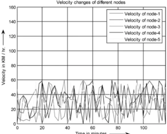
The performance of the proposed algorithm is compared with the algorithm proposed by S. S. Basu and A. Chaudhuri in [3] and non fuzzy algorithm of the authors [6]. In [3] an rithm to elect coordinator and a separate algo-rithm for node movement have been proposed. This algorithm is the centralized one. The algo-rithm proposed in[6]is the distributed one, but the movement control algorithm is not fuzzy-based. To evaluate the performance of this fuzzy logic based distributed algorithm to maintain the connectivity of the network, a network of five nodes and their initial coordinates(1.5,3), (0.5,2),(2,3),(3,1), and(4,1)have been con-sidered. Velocity changes of the different nodes are shown graphically for the algorithm pro-posed in [3], [6] and this paper in Figure 16a and Figure 16b and Figure 16c respectively. From the results presented in 16a, 16b and 16c, it is seen that the proposed algorithm is very effective in maintaining the connectivity, com-pared to others. This algorithm has the addi-tional feature of capability of restoring connec-tivity if it is hampered due to a faulty node. This feature is not available in other algorithms. Sta-bility of the nodes is hampered by the sudden change of velocity. But from the above com-parison it is clear that the algorithm proposed in this paper is giving better stability, compared to others.
8. Conclusion
From the simulations it is clear that the net-work connectivity is maintained between two successive beacon intervals most of the time, hence the routing overhead is also reduced to a large extent. Due to the distributed nature of the scheme, control overhead is also distributed equally among all the nodes of the network. Nodes act as intelligent agents as fuzzy-based movement control scheme is introduced. More-over, the algorithm has the capability to restore connectivity if it is broken due to a faulty node. In the future, hardware implementation with op-timized power consumption of the algorithm may be proposed.
Figure 16a.Velocity changes of the nodes for the algorithm in[3].
Figure 16b.Velocity changes of the nodes for the algorithm in[6].
References
[1] S. S. BASU AND A. CHAUDHARI, Self-adaptive
Topology Management for Mobile Ad-Hoc Net-work, IE (I) Journal-ET, Vol. 84, pp. 7–12, July 2003.
[2] DAVID B. JOHNSON, DAVID A. MALTZ AND JOSH
BROCH, DSR: The Dynamic Source Routing Pro-tocol for Multi-Hop Wireless Ad-Hoc Networks, Ad-Hoc Networking, edited by Charles E. Perkins, Chapter 5, pp. 139–172, Addison-Wesley, 2001. [3] SOUMYA SANKARBASU, ATALCHAUDHARI,
Self-Adaptive MANET: A Centralized Approach, Foun-dations of Computing and Decision Sciences, Vol. 29, pp. 271–286 2004.
[4] A. NASIPURI, R. CASTANEDA,ANDS. R. DAS, Per-formance of Multipath Routing for On-demand Protocols in Mobile Ad-hoc Networks,Mobile Net-work Applications, Vol. 6, No. 4, pp. 339–349, 2001.
[5] S. SAMANTA, S. S. RAY, S. SENGUPTA, M. K.
NASKAR, A Novel Algorithm for Managing
Net-work Configuration, in Proc. Asian International Mobile Computing Conference (AMOC2007), pp. 51–58, January 2007, Kolkata.
[6] JISHANMEHEDI, SURENDRAS. DALU,AND M. K.
NASKAR, A Distributed Approach to Maintain
Con-nectivity of Nodes in Mobile Ad-Hoc Networks, in Proc. International Conference on Intelligent Systems & Networks (IISN2007), pp. 353–358, February 2007, Haryana.
[7] AVIK RAY, KANAD BASU, SAMIR BISWAS, MRI
-NAL K. NASKAR, A Novel Distributed Algorithm for Topology Management in Mobile Ad-hoc Networks, in Proc. International Conference on Computers and Devices for Communication 2006 (CODEC06), pp. 99–102, December 2006, Kolkata, India.
[8] ELIZABETHM. ROYER ANDCHAI-KEONGTOH, A
Review of Current Routing Protocols for Ad-hoc Mobile Wireless Networks, IEEE Personal Com-munications, Vol. 6, No. 2, pp. 46–55, April 1999.
[9] JISHANMEHEDI, SURENDRAS. DALU,AND M. K.
NASKAR, Performance Comparison of Some
Rout-ing Protocols for Mobile Ad-Hoc Networks, in
Proc. National Conference (INDIACom2007), pp. 205–208, 212, February 2007, Delhi.
[10] C. E. PERKINS ANDP. BHAGWAT, Highly Dynamic
Destination Sequenced Distance Vector Routing (DSDV)for Mobile Computers,ACM SIGCOMM, Vol. 24, No. 4, pp. 234–244, October 1994. [11] J. BROCH, D. A. MALTZ, D. B. JOHNSON, Y. C. HU
ANDJ. JETCHEVA, A Performance Comparison of
Multi-hop Wireless Ad-hoc Network Routing Pro-tocols, inProc. Mobile Computing and Networking, pp. 85–97, 1998.
[12] T. KORAKIS, G. JAKLLARI, AND L. TASSIULAS, A
MAC Protocol for Full Exploitation of Directional Antennas in Ad-hoc Wireless Networks, inProc. 4th ACM International Symposium on Mobile Ad-hoc Networking & Computing, ACM Press, pp. 98–107, 2003.
[13] R. WATTENHOFER, L. LI, P. BAHL ANDY. M. WANG,
Distributed Topology Control for Power Efficient Operation in Multi-hop Wireless Ad-hoc Networks, inProc. IEEE INFOCOM, April 2001.
[14] R. RAMNATHAN ANDR. ROSALES-HAIN, Topology
Control of Multi-hop Radio Networks Using Trans-mit Power Adjustment, inProc. IEEE INFOCOM, pp. 403–404, March 2002.
[15] C. BETTSTETTER, On the Minimum Node Degree
and Connectivity of a Wireless Multi-hop Network, inProc. ACM MOBIHOC, pp. 80–91, June 2002.
[16] F. BAI, N. SADAGOPAN, A. HELMY, Important: a Framework to Systematically Analyze the Impact of Mobility on Performance of Routing Protocols for Ad-hoc Networks, INFOCOM 03, Vol. 2, pp. 825–835, San Francisco, California, USA, March 2003.
[17] T. CAMP, J. BOLENG,ANDV. DAVIES, A Survey of Mobility Models for Ad-hoc Network Research,
Wireless Communications & Mobile Computing (WCMC): Special Issue on Mobile Ad-Hoc Net-working: Research, Trends and Applications, Vol. 2, No. 5, pp. 483–502, September 2002.
[18] J. BOUDEC, J.-Y. L. BOUDEC AND M. VOJNOVIC´,
Perfect Simulation and Stationarity of a Class of Mobility Models, inProc. IEEE Information Com-munications Conference (INFOCOM05),pp. 72–79, 2005.
[19] JINSHAN LIU, FRANCOISESAILHAN, Group
Man-agement for Mobile Ad-Hoc Networks: Design, Implementation and Experiment, inProc. MDM 05, pp. 192–199, Ayia Napa, Cyprus, 2005.
[20] KIHWAN KIM, YING CAI AND WALLAPAK TA -VANAPONG, Sharing Location Dependent
Experi-ences in MANET, inProc. 7th International Con-ference on Mobile Data Management (MDM06), pp. 69.
[21] E. NATSHEH, A. B. JANTAN, S. KHATUN ANDS. SUB -RAMANIAM, Fuzzy Reasoning Approach for Local
Connectivity Management in Mobile Ad-hoc Net-works,International Journal of Business Data Com-munications and Networking, Vol. 2, Issue 3, pp. 1–18, 2006.
[22] FAN BAI, NARAYANAN SADAGOPAN, AHMED
HELMY, The Important Framework for Analyzing
the Impact of Mobility on Performance of Routing Protocols for Ad-hoc Networks,Ad-Hoc Networks Journal – Elsevier Science, Vol. 1, Issue No. 4, pp. 383–403, November 2003.
[24] JISHANMEHEDI, M. K. NASKAR, A Fuzzy Based
Distributed Approach to Maintain Connectivity of Nodes in Mobile Ad-Hoc Networks Considering Pursue Mobility Model, International Journal of Computational Intelligence: Theory and Practice, Vol. 4, No. 2, pp. 79–84, 2009.
[25] SCOTTIEBARNES ANDLAFELOW, Basic Essentials:
Global Positioning System,Globe Pequot. Pv., June 2000.
[26] J. BIH, Paradigm Shift- An Introduction to Fuzzy Logic,IEEE Potentials, 25(1), pp. 6–21, 2006.
[27] ELLIOT D. KAPLAN, Understanding GPS: Princi-ples & Applications, Arleets House, March 1996.
[28] AMITKONAR,Computational Intelligence: Princi-ples, Techniques and Applications, Springer, 2005.
Received:October, 2009
Revised:June, 2012
Accepted:June, 2012
Contact addresses:
Jishan Mehedi Department of Electronics and Communication Engineering National Institute of Technology Silchar, Assam-788010 e-mail:[email protected]
M. K. Naskar Advanced Digital and Embedded Systems Lab Department of Electronics and Telecommunication Engineering Jadavpur University Kolkata-700032 e-mail:[email protected]
DR. JISHANMEHEDIreceived the B. Tech degree in Electronics and Communication Engineering from the University of Kalyani, M. E. Tel. E and PhD degree in Electronics and Telecommunication Engineering from Jadavpur University. He worked as faculty member in Dumkal In-stitute of Engineering and Technology from 2002 to 2008. Currently, he is working as Assistant Professor in ECE Department at NIT, Silchar, Assam-788010, India. His research interests include mobile ad-hoc networks, wireless sensor networks and digital system design.