Sharif University of Technology
Scientia IranicaTransactions B: Mechanical Engineering www.scientiairanica.com
Designing an optimal fuzzy controller for a fuel cell
vehicle considering driving patterns
M. Kandi-D
, M. Soleymani and A.A. Ghadimi
Department of Mechanical Engineering, Faculty of Engineering, Arak University, Arak, P.O. Box 38156-8-8349, Iran. Received 1 May 2014; received in revised form 21 December 2014; accepted 13 April 2015
KEYWORDS Optimal fuzzy controller; FCV;
Driving pattern; PSO.
Abstract. Design of an optimal fuzzy scheme for a fuel cell/battery vehicle to control the power ow between the main components, i.e. the fuel cell, electric motor, and battery, under various driving conditions, is considered in this paper. For this purpose, rstly, the optimum sizes of the main components are calculated by means of a Particle Swarm Optimization (PSO) algorithm. Subsequently, a Fuzzy Logic Controller (FLC) is devised for the control of the power ow. Finally, the FLC is optimized for various driving patterns and an optimal control scheme, based on PSO application, is proposed for energy management of the Fuel Cell Vehicle (FCV) under various trac conditions. In each one of the mentioned stages, the same optimization process is conducted by applying a Genetic Algorithm (GA) for comparison with the result of the PSO. The results of the computer simulation are compared over diverse driving conditions. The results give an acceptable indication of progress in fuel economy for various driving patterns, using the proposed optimal fuzzy controller.
© 2016 Sharif University of Technology. All rights reserved.
1. Introduction
Present-day society has substantial dependence on fos-sil fuels since they supply power to vehicles, machines and even power stations. The enormous global growth of car production is inexorable due to transformation of the social structure by urbanization. There is no disputing the fact that this growing trend comes with some direct consequences. The overall picture is analogous to a chain of events, since oil assumes a key role in the development of transportation. Air pollution and climate change are major drawbacks associated with burning oil, and vehicles are perceived as potential candidates for its consumption. Global warming, which is one of the most vigorously debated
*. Corresponding author. Tel.: +98 861 32625722; Fax: +98 861 2774031
E-mail addresses: [email protected] (M. Kandi-D); [email protected] (M. Soleymani);
[email protected] (A.A. Ghadimi)
topics on Earth, is attributed to the accumulation of greenhouse gases like carbon dioxide, the product of igniting fossil fuels in the atmosphere. Overall, accomplishing environmental and energy sustainability falls under the direct inuence of vehicles and personal transportation [1,2].
Running on petrol and diesel fuel, conventional vehicles are counted as a main contributor to air pollu-tion and carbon dioxide release. Furthermore, there are other exhaust fumes from conventional vehicles, inclu-sive of carbon monoxide and nitrogen oxides. In short, the drawbacks of conventional vehicles encompass high energy loss, undue detrimental exhaust emissions, and heavy reliance upon a sole fuel source. Conventional vehicles also employ a sole Internal Combustion Engine (ICE) as the power source [3].
Electric vehicles encompass a range of virtues and issues competing against one another. By far, the main benets gained from electric vehicles are the absence of emissions and high eciency. It is worth remembering that the positive aspects of electric
vehicles are attributable to the absence of internal combustion engines. However, high cost, limited driving range and conned charge sustainability are still conceived as worrying drawbacks associated with electric vehicles [4,5].
Hybrid Electric Vehicles (HEVs) are one of the alternatives proposed to address the issues associated with the energy crises and global warming. HEVs, which are comprised of an Internal Combustion Engine (ICE) as the primary power source and an electric motor as the secondary power source, surmount con-ventional and EVs related challenges, such as high cost and limited driving range, since they need not plug in to charge. Moreover, the fuel consumption of HEVs is greatly decreased in comparison with conventional vehicles. Nevertheless, they still run on fossil fuels [6]. FCVs embrace hybrid vehicles and hydrogen fuel cell technology to elude exhaust emissions and optimize fuel consumption [7]. Fuel cell vehicles are generally viewed as zero emission vehicles, thanks to omission of the combustion process. In FCVs, hydrogen and oxygen are translated into electricity by means of fuel cells. Hence, no tailpipe pollutants are produced in order to propel the vehicle. Water and heat are counted as products of the mentioned reaction. In automotive applications, virtually all the signicant manufacturers have declared that plans for commercializing FCVs are on the horizon [8].
In particular, the Proton Exchange Membrane Fuel Cell (PEMFC) is an auspicious candidate for FCVs, owing to its inherent characteristics, which include high power density, higher eciency and lower temperature operation, in comparison with ICEs [9]. Nevertheless, due to the unsteady power demand of a vehicle during its operation, application of a sole FC system as the power source is not appropriate. As a general rule, combining FC systems with an Energy Storage System (ESS) diminishes cost, enhances per-formance, and provides fuel economy [10].
Batteries are a prime example of ESS in FCV applications. Among dozens of existing batteries, Lithium-ion batteries are the most promising for ap-plying in FCVs, by virtue of their energy density and power density range [11].
Since FC and battery have diverse dynamic char-acteristics, an appropriate Energy Management Strat-egy (EMS) seems to be vital for this system [12,13]. The EMS, preset in the vehicle controller, is to control the power ow between the FC system, the ESS, and the drive train. There are a number of EMSs for FCVs, such as intelligent-based EMSs and optimization-based EMSs. Among intelligent-based EMSs, FLC has a quite suitable performance, as reported in many stud-ies [14-16]. Overall, FLC furnishes rm deduction, from inexact and inexplicit information, about the state of the system in an undemanding way. Classical control
demands profound knowledge of a system and accurate equations. In contrast, FLC permits modeling con-voluted systems by employing an expert's knowledge and experience. In comparison to regular approaches, FLC presents an appropriate performance in nonlinear systems where acquiring an entire mathematical model is very demanding. Furthermore, another strength ascribed to such a control approach, in comparison with other methods like neural networks, is that it is entirely independent of former data. For the reasons above, it is evident that FLC has a fairly proper conguration for FCVs [17,18].
Utilizing unaided FLC provokes some debates, as follows: Firstly, FLC is designed based on the technical expertise of the designer. Therefore, it cannot succeed in accomplishing higher eciency under all operating conditions of a complex system like FCV. Secondly, driving patterns, which represent real trac conditions and have a profound impact on the fuel consumption of the FCV, are not incorporated in the design of the control strategy [19]. From this standpoint, the most important course of action to address these issues is to employ optimization algorithms for modelling an optimal FLC. In this case, the impact of driving patterns on fuel consumption is considered in the control design of the FCV.
There are dozens of algorithms applicable to the optimization process of complex systems. They can fall into diverse categories; for instance, local optimization methods against global ones; a deterministic opti-mization algorithm versus a stochastic optiopti-mization algorithm; or the gradient-based algorithm versus the derivative-free algorithm. The main drawback of local optimization methods is that they do not search the whole design space for nding the answer. Unlike local optimization methods, global optimization algorithms are capable of nding the best optimum answer in FCV applications. Derivative-free and stochastic optimiza-tion methods, despite gradient-based and deterministic methods, are not dependent on the derivatives, and can deal with inherent nonlinear or discontinuous systems eectively. The Genetic Algorithm (GA) and Particle Swarm Optimization (PSO) are perceived as potential means for vehicular applications, since they are tted into global, stochastic, derivative-free optimization categories [20].
There are a number of approaches to identify ex-isting situations and project future driving conditions. The main techniques fall into three categories: The Global Positioning System (GPS) or Intelligent Trans-portation System (ITS)-based method, which acquires several driving features, such as speed, acceleration etc. to implement in dierent control strategies like dynamic programming [21,22]. Statistic and clustering analysis-based approaches, in which future driving conditions are predicted by scrutinizing former and
current driving information [23]. The sentence is not complete. The last category is Markov chain-based technique, which proves helpful for stochastic process prediction.
In this paper, a new optimal fuzzy controller based on the PSO algorithm is suggested to control the power ow between the FCV main components, i.e. Lithium-ion battery, PEMFC, and electric motor. For this purpose, rstly, the optimal sizes of the aforementioned components are determined. A back-ward/forward simulation approach is then employed to formulate the power ow in the drive train system over various driving conditions. Finally, the optimal con-troller is implemented. It is worth remembering that the same optimization process is done by utilizing the GA method, and the ultimate outcomes are compared with PSO.
This paper is organized as follows: Section 2 presents a description of the power train system and driving cycles. Section 3 describes the design of the primary FLC and the optimal FLC. Section 4 presents the simulation results. Finally, conclusions are given in Section 5.
2. Modeling and simulation 2.1. Drive train
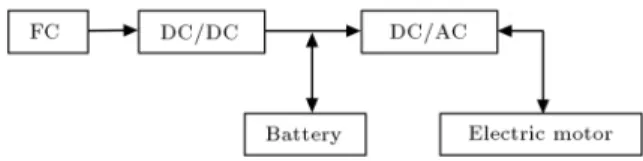
A(F C + B) architecture is a common structure in FCVs [25]. As shown in Figure 1, in this structure,
Figure 1. Drive train.
a battery is regularly connected to the FC system in order to supply additional power for starting the system. Unlike the PEMFC, which is linked to the DC bus by a DC/DC converter, the battery is directly connected to the bus. The total power, provided by the FC and the battery, ows towards the Electric Motor (EM) after passing the DC/AC inverter. The electric motor converts the electric energy into mechanical energy to propel the vehicle or to generate electricity for the purpose of charging the batteries [26].
Some of the specications of the vehicle and its key components are explained in Table 1.
2.2. Driving cycles
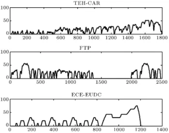
It is dicult to precisely describe the driving pat-terns and speed variations under all trac conditions. However, some representative driving cycles have been developed to emulate typical trac environments [27]. Driving cycles are standard vehicle speed versus time proles developed for testing vehicle exhaust emissions and fuel consumption in a standard laboratory test. In this paper, three diverse driving cycles, the Federal Test Procedure driving cycle (FTP), the Economic
Table 1. Some data regarding the vehicle and its chief components. Specications
Vehicle
Class: Average Model: Saturn SL Total mass: 1380 kg
Dimensions (mm): Length: 4478, width: 1717, height: 1285 Transmission type: Automatic, 5-speed
Fuel cell system
Type: PEMFC
Model: Based on ANL (Argonne National Laboratory) model Fuel type: Hydrogen
Peak eciency: 60%
Maximum output power: 44 kw FC weight: 223 kg
Stack and reformer pressure drop: 15 to 30 kPa
Battery
Type: Lithium ion battery Model: Saft (6 Ah) Number of cell: 29 Maximum voltage: 3.9 V
Electric motor
Model: Westinghouse induction electric motor (inverter) Maximum output power: 44 kw
Peak eciency: 92% Weight: 91 kg
Figure 2. TEH-CAR, FTP, and ECE-EUDC driving cycle.
Figure 3. Backward-facing simulation.
Commission for Europe and Extra Urban Driving Cycle (ECE-EUDC) [28], and Tehran city driving cycle (TEH-CAR) [29], are employed in a simulation process. The aforementioned driving cycles, which are employed in this study, are shown in Figure 2.
2.3. Simulation approach
Considering the direction of computation, simulation methods come into two categories, including forward-facing and backward-forward-facing. In the latter, which resembles the standard laboratory emission test, the simulation chain, as shown in Figure 3, starts with the power demand at the wheels and continues until the operating point of the fuel cell, which can be translated to fuel consumption. However, in the rst approach, the simulation process commences with the fuel converter coming towards the wheels. In this study, a backward/forward facing simulation procedure is utilized to formulate the power ow.
3. Energy management 3.1. Component sizing
Designing appropriate component sizes, to achieve preferable vehicle performance, plays a signicant role in the control design of a FCV. In general, a hybrid power train is composed of electric motors, power electronics converters, energy storage devices, fuel converters, and so on. Thus, the complexity of a hybrid power train is far more convoluted than a conventional one. A parametric design can be utilized to evaluate the size of the main components in hybrid vehicles [30]. In this study, design parameters
encom-pass the maximum power of the fuel converter (fuel cell), the maximum power of the electric motor, and the number of battery modules. As mentioned earlier, among variant global algorithms, GA and PSO seem to be potential candidates for the component sizing process, as they do not converge to the local extrema. It is worth mentioning that the prime merit of the PSO algorithm is that fewer parameters need to be tuned in comparison to the GA. Furthermore, the equations are more straightforward and some opera-tors, such as crossover, mutation, and selection, are not needed. On account of the mentioned merits, the PSO algorithm is able to converge to optimum at a quite rapid pace, compared to evolutionary algorithms like GA. It should be noted that selecting suitable constants is highly important in gaining a superior performance, while employing PSO.
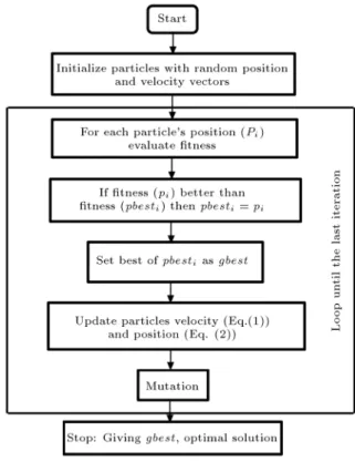
In this paper, Particle Swarm Optimization (PSO) is utilized for determining the desired compo-nent sizes. The PSO is a swarm intelligence technique and an evolutionary algorithm, inspired by the ocking behavior of birds, which was developed by Kennedy and Eberhart [31]. Generally, the PSO algorithm commences searching by a random population, or swarm, of candidate solutions, called particles. These particles go around the search-space, employing some simple formulas, to trace the solutions. While searching the whole space, particles are aware of their own best position and the entire swarm's best position. When particles notice an improvement in positions, they guide the swarm towards it. The process is repeated until achieving a satisfactory solution. The owchart representing the PSO algorithm is shown in Figure 4.
The velocity of each particle is updated as follows: vn+1
i =kvin+ 1rand1(pbesti pni)
+ 2rand2(gbest pni); (1)
where vn+1
i is the velocity of particle i at iteration n+1,
k is the weighing factor, 1 and 2 are the weighing
factors, rand1 and rand2 are two random numbers
between 0 and 1, pn
i is the position of particle i at
iteration n, pbestiis the best position of particle i, and
gbest is the best position of the swarm.
Similarly, the position is updated as follows: pn+1
i = pni + vn+1i : (2)
As mentioned before, this study attempts to reach fuel economy without sacricing vehicle performance. Therefore, Partnership for the Next Generation of Vehicle (PNGV) constraints [32] is considered a penalty for the tness function. The penalty is used to update pbest and gbest for each particle. For a particle i, the pbest value is updated if the penalty of the particle is less than the previous best penalty. The same is
Figure 4. PSO owchart.
Table 2. Design variables limitations. Variable
bounds
Upper bound
Lower bound
SFC 1.3 0.7
SEM 1.3 0.1
NBM 35 5
done when gbest is updated. This makes sure that the objective function is maximized. In addition to the PNGV passenger constraints, some limitations are imposed on design variables, as listed in Table 2.
In this table, SF C is the scaling factor for the
fuel converter, SEM is the scaling factor for the electric
motor, and NBM is the number of battery modules. In
order to employ the PSO algorithm, a tness function is demanded. Penalty functions are utilized to apply the constraints to the problem. The tness function is formulated as follows:
F (x) = 1 Fc
NXcon i 1
i Ci(x); (3)
where F (x) is the tness function, Fc is fuel
con-sumption, Ci(x) is the penalty function of the related
constraint, and iis the amount of punishment for each
constraint, attained by trial and error. It should be noted that as a control strategy has no considerable impact on the sizing procedure [33], the component sizing process is done by employing the thermostat control strategy.
3.2. Fuzzy logic controller
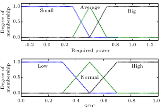
In this study, FLC has been employed for the energy management of the system. Several advantages can be counted for this control approach. Firstly, it is based on verbose statements, which provides the capability of integrating the knowledge of an expert into the design procedure. Moreover, it does not need an exact model of the system. It is a key advantage in the FCV, where, in the backward-facing simulation approach, an explicit model of the system is not available. Furthermore, FLC has an inherent robustness which can cope with uncertainties in the control design procedure. The employed controller is a PD FLC, which incorporates the required power and the State Of Charge (SOC) as inputs, and requested power from the FC as the output. Characteristics of the FLC are also as follows: The fuzzy system type is Mamdani, the inference engine is AND (minimum operator) and diuzication is centroid. The fuzzy system is shown in Figure 5.
Besides, the fuzzy control surface is shown in Figure 6. Each input and output has three MFs, as shown in Figure 7. In Figure 7, the trapezoid MF is used for small, big, low, and high MFs in inputs and output. The triangle MF is employed for Average and Normal MFs in inputs and output. The fuzzy reasoning rules with 9 items are given in Table 3.
3.3. Optimal fuzzy logic controller
In the FLC discussed in the foregoing section, the membership functions are distributed uniformly over
Figure 5. Fuzzy system.
Table 3. Fuzzy reasoning rules. Rules descriptions
If (required power is small) and (SOC is low) then (output power is average) If (required power is small) and (SOC is normal) then (output power is small) If (required power is small) and (SOC is high) then (output power is small) If (required power is average) and (SOC is low) then (output power is big) If (required power is average) and (SOC is normal) then (output power is average) If (required power is average) and (SOC is high) then (output power is average) If (required power is big) and (SOC is low) then (output power is big)
If (required power is big) and (SOC is normal) then (output power is big) If (required power is big) and (SOC is high) then (output power is average)
Figure 7. Input membership functions.
the universe of discourse. Therefore, it does not necessarily work optimally over variant driving cycles. In other words, some parameters need to be modied in the FLC, for each driving cycle, in order to achieve optimal fuel consumption in the corresponding trac condition [34]. In designing a FLC, driving patterns should be taken into consideration because driving habits are dissimilar in dierent areas. Thus, they may exert a strong inuence over operating points of the FC and, consequently, on fuel consumption.
In this section, the application of PSO to create a novel optimal FLC (Fuzzy-PSO) is represented. An optimal fuzzy controller is a FLC in which some pa-rameters are adjusted, concerning the driving pattern, by an optimization algorithm to minimize the tness function to a feasible extent [35]. In this paper, PSO is exploited as an optimizer. The optimum sized pa-rameters, achieved in Section 3, are utilized as scaling factors of main components. The tness function is akin to the one described in Eq. (3), in Section 3. However, the design parameters are dissimilar. In this case, the constructing parameters of the input membership functions are considered the optimization parameters. As seen in Figure 7, considering the symmetry of membership functions, which is assumed to be valid even after adjustment, a set of membership functions corresponding to each input can be described
Figure 8. Design variables.
by 5 parameters. Thus, the number of optimization parameters comes to 10. As shown in Figure 8, the rst trapezoid MF, for the required power, can be described by three points. The rst and second points are considered as x1and x2, and the third point is xed at
0.5. The triangle MF, for the required power, is viewed as x3and depicted by three points. Finally, the second
trapezoid MF, for the required power, is specied by three points. The rst point is set at 0.5 and the other points, x4and x5, are perceived as design variables.
It should be noted that simulation time is heavily inuenced by the number of design variables. Hence, a simple FLC has been employed in this study to decrease computational eort.
4. Simulation study and results analysis
The performance of the proposed optimal controller is assessed via extensive simulations carried out over various driving patterns. In this section, rstly, the sizing results are presented. The performance of the optimal controller, in comparison with the initial fuzzy and thermostat controller, for various driving patterns, is subsequently evaluated. Finally, the results are discussed.
Figures 9 and 10 depict the optimization trend, for the TEH-CAR driving cycle, in the optimiza-tion procedure of the component sizes. As seen in these gures, the predened tness function increases generation by generation, employing continuous fuel economy improvement, until it reaches a steady level. The optimization process has been conducted for 60 generations and each generation has a population of 70. The same procedure has been done for the other driving
Figure 9. Objective function trends by PSO.
Figure 10. Objective function trends by GA.
Figure 11. Fuel consumption.
Table 4. Size of main components.
Components Size
GA PSO
Fuel cell 44 kw 42 kw
Electric motor 44.5 kw 44 kw Battery module (number) 30 29
cycles. Since the control strategy does not aect the optimization results, the thermostat control strategy has been utilized during the optimization process for all driving cycles. Table 4 provides the size of the main components after optimization.
Figure 11 presents fuel consumption before and after the sizing process at various driving patterns. As seen in this gure, by applying the sizing procedure, fuel consumption has been decreased for all mentioned driving patterns. Employing the optimal sizes acquired from the sizing procedure, the fuzzy controller has been implemented on the fuel cell model. Moreover, the parameters of the fuzzy controller are tuned using the particle swarm optimization approach. Figure 12
Figure 12. Objective function trend (PSO).
Figure 13. Objective function trend of TEH-CAR driving cycle (GA).
Figure 14. Adjusted MFs.
shows the objective function optimization trend of the fuzzy controller for the three driving cycles. Figure 13 represents the optimization trend of the objective func-tion for the TEH-CAR driving cycle, by means of GA. The same process has been conducted for other driving cycles. Furthermore, Figure 14 presents the optimized MFs of optimal FLC for each driving cycle. As clear from Figure 14, the MFs shapes have been considerably aected by the optimization procedure, illustrating the impact of the driving pattern on optimization of the fuzzy controller.
Comparisons of fuel consumption for the FLC and optimal controller for various driving patterns are shown in Figure 15. According to this gure, reduction of fuel consumption is not the same for diverse driving cycles. Overall, a six point ve to seven percent
Figure 15. Fuel consumption comparison.
Figure 16. Fuel cell operating point.
progress in fuel consumption is crystal clear, according to a comparison of the fuel consumption of FLC with optimal FLC. According to Figure 15, the performance of PSO is slightly better than GA in this application. The greatest advantage of the PSO algorithm is the rapid pace of convergence in comparison with GA, which results in a reduction of time in completing the optimization process.
In order to analyze the performance of the em-ployed controllers, the operating points of the fuel cell using diverse controllers for various driving patterns have been examined. Figure 16 depicts the operating points of the fuel cell with the thermostat control strategy, FLC, and optimal FLC under various trac conditions. As seen in this gure, applying optimal FLC to the FCV has a benecial eect on the operating points of the fuel cell system, since they have moved towards the higher eciency region. This alteration in the trend of the operating range is in agreement with previous results, where a drop in fuel consumption was reported utilizing the optimal controller.
There are four individual trac conditions on the inside of the TEH-CAR driving cycle. Since
Figure 17. Optimal FLC MFs.
trac conditions have a considerable inuence on the performance and fuel consumption of a vehicle, it should be incorporated into the design of the fuzzy control scheme. For this purpose, at the second stage, an optimal FLC is designed, with regard to dierent modes in the TEH-CAR driving cycle. The optimal FLC has four modes to embrace each individual trac condition, as shown in Figure 17.
Figure 18. Performance test of the optimal controller.
The performance of the optimal controller is studied. For this purpose, the primary controller is separately optimized for all representative trac conditions, using a PSO approach. The optimized controller is then applied to all trac conditions, including its corresponding one. Figure 18 compares fuel consumption for highway trac conditions with various modes of the controller. As is clear in this gure, the controller, optimized for highway trac conditions, has the best performance for this trac condition. The same results have been obtained for other controllers.
According to Figure 18, it is seen that the optimal controller gives a superb performance when confronting all trac conditions.
5. Conclusion
An optimal FLC for a (FC+B) vehicle, considering the driving pattern, is suggested in this study. The principal purpose is to achieve optimal fuel economy for various driving cycles while maintaining driving performance within a feasible range. For this pur-pose, the optimum sizes of the main components are calculated using a PSO algorithm. A FLC is then devised to control power ow between key components. Meanwhile, the performance of the PSO algorithm, which is perceived as a newcomer in FCV applications, is compared with GA, in the process of optimization. In order to reach the optimal performance of FLC under various trac conditions, rstly, an optimal control scheme, based on the PSO algorithm, is proposed for the three driving cycles. Secondly, a four-mode optimal controller is designed to embrace diverse trac conditions on the inside of the TEH-CAR driving cycle. The results acquired from the simulation stage prove the eectiveness of the proposed controller in tackling various driving patterns in order to attain optimal fuel consumption.
References
1. Crank, J. \The challenges of global warming research", In Crime, Violence, and Global Warming, L. Jacoby 1st Edn., pp. 3-21, Anderson Publishing (2015).
2. Truelove, H. and Parks, C. \Perceptions of behaviors that cause and mitigate global warming and intentions to perform these behaviors", J. of Environmental Psychology, 32(3), pp. 246-259 (2012).
3. Taylor, A.M.K.P. \Science review of internal combus-tion engines", J. of Energy Policy, 36(1), pp. 4657-4667 (2008).
4. Chau, K.T. \Pure electric vehicles", In Alternative Fuels and Advanced Vehicle Technologies for Improved Environmental Performance, R. Folkson, 1st Edn, pp. 655-684, Woodhead Publishing (2014).
5. Mousazadeh, H., Keyhani, A., Mobli, H., Bardi, U., Lombardi, G. and Asmar, T. \Environmental assess-ment of RAMseS multipurpose electric vehicle com-pared to a conventional combustion engine vehicle", J. of Cleaner Production, 17(1), pp. 781-790 (2009).
6. Ehsani, M., Gao, Y. and Emadi, A. \Hybrid electric vehicles", In Modern Electric, Hybrid Electric, and Fuel Cell Vehicle, Fundamentals, Theory, and Design, 2nd Edn., pp. 123-150, Taylor and Francis Group (2010).
7. Mi, C., Masrur, M. and Gao, D.W. \Batteries, ultra-capacitors, fuel cells, and controls", In Hybrid Electric Vehicles, Principles and Applications with Practical Perspectives, 1st Edn, pp. 315-362, John Wiley & Sons (2011).
8. Erdinc, O., Vural, B. and Uzunoglu, M. \A wavelet-fuzzy logic based energy management strategy for a fuel cell/battery/ultra-capacitor hybrid vehicular power system", J. of Power Sources, 194(1), pp. 369-380 (2009).
9. Torreglosa, J.P., Jurado, F., Garcia, P. and Fernandez, L.M. \PEM fuel cell modeling using system identica-tion methods for urban transportaidentica-tion applicaidentica-tions", Int. J. of Hydrogen Energy, 36(1), pp. 7628-7640 (2011).
10. Erdinc, O. and Uzunoglu, M. \Recent trends in PEM fuel cell-powered hybrid systems: Investigation of application areas, design architectures and energy management approaches", Renewable and Sustainable Energy Reviews, 14(1), pp. 2874-2884 (2010).
11. Kojima, T., Ishizu, T., Horiba, T. and Yoshikawa, M. \Development of lithium-ion battery for fuel cell hy-brid electric vehicle application", J. of Power Sources, 189(1), pp. 859-863 (2009).
12. Melo, P., Araujo, R.E. and de Castro, R. \Overview on energy management strategies for electric vehicles -Modeling, trends and research perspectives", 3rd Int. Youth Conf. on Energetics, pp. 1-9, Leiria, Portugal (2011).
13. Wang, F.C., Gao, C.Y. and Li, S.Y. \Impacts of power management on a PEMFC electric vehicle", Int. J. of Hydrogen Energy, 39(30), pp. 17336-17346 (2014).
14. Mohammedi, M., Kraa, O., Becherif, M., Aboubou, A., Ayad, M.Y. and Bahri, M. \Fuzzy logic and passivity-based controller applied to electric vehicle using fuel cell and supercapacitors hybrid source", Energy Procedia, 50, pp. 619-626 (2014).
15. Hemi, H., Ghouili, J. and Cheriti, A. \A real time fuzzy logic power management strategy for a fuel cell vehicle", Energy Conversion and Management, 80, pp. 63-70 (2014).
16. Gao, D., Jin, Z. and Lu, Q. \Energy management strategy based on fuzzy logic for a fuel cell hybrid bus", J. of Power Sources, 185(1), pp. 311-317 (2008).
17. Kraa, O., Becherif, M., Ayad, M.Y., Saadi, R., Bahri, M., Aboubou, A. and Tegani I. \A novel adaptive op-eration mode based on fuzzy logic control of electrical vehicle", Energy Procedia, 50, pp. 194-201 (2014).
18. Gao, D., Jin, Z. and Lu, Q. \Energy management strategy based on fuzzy logic for a fuel cell hybrid bus", J. of Power Sources, 185(1), pp. 311-317 (2008).
19. Ryu, J., Park, Y. and Sunwoo, M. \Electric powertrain modeling of a fuel cell hybrid electric vehicle and development of a power distribution algorithm based on driving mode recognition", J. of Power Sources, 195(1), pp. 5735-5748 (2010).
20. Panday, A. and Om Bansal, H. \A review of optimal energy management strategies for hybrid electric vehi-cle", Int. J. of Vehicular Technology, 2014, Article ID 160510, 19 pages (2014).
21. Zhu, D. and Xie, H. \Control strategy optimization of the hybrid electric bus based on remote self-learning driving cycles", Vehicle Power and Propulsion Conf., Harbin, pp. 1-5 (2008).
22. Gong, Q., Li, Y. and Peng, Z. \Optimal power manage-ment of plug-in HEV with intelligent transportation system", IEEE/ASME Int. Conf. on Advanced intelli-gent Mechatronics, ETH Zurich, Switzerland, pp. 1-6 (2007).
23. Montazeri-Gh, M. and Fotouhi, A. \Trac condition recognition using the k-means clustering method", Int. J. of Scientia Iranica, 18(4), pp. 930-937 (2011).
24. Zhang, Y. \DIRECT algorithm and driving cycle recognition based optimization study for hybrid elec-tric vehicle", Ph.D. Thesis, Dept. Mech. Eng., Beijing Inst. of Tech., Beijing, China (2010).
25. Lachichi, A. and Schoeld, N. \Comparison of DC-DC converter interfaces for fuel cells in electric vehicle applications", Proceedings of the IEEE Vehicle Power and Propulsion Conference, Windsor, UK, pp. 6-8 (2006).
26. Zhu, Z.Q. and Howe, D. \Electrical machines and drives for electric, hybrid, and fuel cell vehicles", Proceedings of the IEEE, 95(4), pp. 746-765 (2007).
27. Fu, J. and Gao, W. \Principal component analysis based on drive cycles for hybrid electric vehicle", 5th IEEE Vehicular Power and Propulsion Conference, Dearborn, MI, pp. 7-11 (2009).
28. http://www.dieselnet.com/standards/cycles.
29. Montazeri-Gh, M. and Naghizadeh, M. \Development of car drive cycle for simulation of emissions and fuel economy", 15th European Simulation Symposium Proceedings, Delft, the Netherlands, pp. 1301-1317 (2003).
30. Kim, M., Sohn, Y.J., Lee, W.Y. and Kim, C.S. \Fuzzy control based engine sizing optimization for a fuel cell/battery hybrid mini-bus", J. of Power Sources, 178(1), pp. 706-710 (2008).
31. Kennedy, J. and Eberhart, R.C. \Particle swarm opti-mization", Proceedings of IEEE International Confer-ence on Neural Networks, Piscataway, NJ., pp. 1942-1948 (1995).
32. Moore, T.C. and Lovins, A.B., Vehicle Design Strate-gies to Meet and Exceed PNGV Goals. Electric and Hybrid Vehicles, Implementation of Technology SAE Special Publication, SP-1105, pp. 79-121 (1995).
33. Montazeri-Gh, M., Poursamad, A. and Ghalichi, B. \Application of genetic algorithm for optimization of control strategy in parallel hybrid electric vehicles", J. of the Franklin Institute, 343, pp. 420-435 (2006).
34. Poursamad, A. and Montazeri, M. \Design of genetic-fuzzy control strategy for parallel hybrid electric vehi-cles", Control Engineering Practice, 16(1), pp. 861-873 (2008).
35. Li, C.Y. and Liu, G.P. \Optimal fuzzy power control and management of fuel cell/battery hybrid vehicles", J. of Power Sources, 192(1), pp. 525-533 (2009).
Biographies
Mohsen Kandi-D is currently a graduate student of Mechanical Engineering at Arak University, Iran, working on the control strategy of fuel cell vehicles. Mehdi Soleymani received his BS, MS, and PhD degrees in Mechanical Engineering from Iran University of Science and Technology, Tehran, Iran, in 2000, 2003, and 2008, respectively. Since February, 2009, he has been with the Department of Mechanical Engineering at Arak University, Arak, Iran, where he is currently Assistant Professor and Director of the Systems Simu-lation and Control Laboratory. His research interests include vehicular systems control.
Ali Asghar Ghadimi received his BS, MS and PhD degrees in Power Engineering in 1999, 2002 and 2008, respectively. He is currently Assistant Professor and research member in the Department of Electrical En-gineering at Arak University, Arak, Iran. His research interests are in the area of renewable energy, fuel cells, and hybrid electrical vehicles.