Duct Design in Subsonic and Supersonic
Flow Regimes with and without Normal
Shock Waves Using Flexible String Algorithm
M. Nili-Ahmadabadi
1;, M. Durali
2, A. Hajilouy-Benisi
1and F. Ghadak
3Abstract. In this investigation, the Flexible String Algorithm (FSA) used before for the inverse design of 2D subsonic ducts is developed and applied for the inverse design of subsonic and supersonic ducts with and without normal shock waves. In this method, the duct wall shape is changed under a novel algorithm based on the deformation of a virtual exible string in a ow. Deformation of the string due to the local ow conditions resulting from changes in the wall geometry is performed until the target shape satisfying the prescribed walls pressure distribution is achieved. The ow eld at each shape modication step is analyzed using an Euler equation solution by the AUSM method. Some validation test cases and design examples in subsonic and supersonic regimes are presented here, which show the robustness and exibility of the method in handling the complex geometries in various ow regimes. In the case of unsymmetrical ducts with two unknown walls, the FSA is modied to increase the convergence rate signicantly. Also, the eect of duct inlet and outlet boundary conditions on the convergence of the FSA is investigated. The FSA is a physical and quick converging approach and can eciently utilize ow analysis codes as a black box. Keywords: Duct design; Subsonic; Supersonic; Normal shock; FSA; Internal ow; Inviscid.
INTRODUCTION
Duct Design, such as intakes, manifolds, duct reducers, compressor and turbine blades etc. is based on wall shape determination, so that the ow is opti-mum. Often, both Computational Fluid Dynamics (CFD) and design algorithms are involved in solving an optimal shape design problem. The limitations and computational cost of the design techniques are challenging problems for present time computational technology.
One of the optimal shape design methods is the Surface Shape Design (SSD). The SSD in uid ow problems usually involves nding a shape associated with a prescribed distribution of surface pressure or
1. School of Mechanical Engineering, Center of Excellence in Energy Conversion, Sharif University of Technology, Tehran, P.O. Box 14588-89694, Iran.
2. School of Mechanical Engineering, Center of Excellence in Design, Robotics and Automation, Sharif University of Tech-nology, Tehran, 14588-89694, Iran.
3. Qadr Aerodynamic Research Center, Imam Hossein Univer-sity, Tehran, Iran.
*. Corresponding author. E-mail: [email protected] Received 14 March 2009; received in revised form 20 December 2009; accepted 22 February 2010
velocity. It should be noted that the solution of a SSD problem is not generally an optimum solution in a mathematical sense. It just means that the solution satises a Target Pressure Distribution (TPD) which resembles a nearly optimum performance [1].
There are, basically, two dierent algorithms for solving SSD problems: decoupled (iterative) and cou-pled (direct or non-iterative). In the coucou-pled solution approach, an alternative formulation of the problem is used, in which the surface coordinates appear (ex-plicitly or im(ex-plicitly) as dependent variables. In other words, coupled methods tend to nd the unknown part of the boundary and the ow eld unknowns simultaneously in a (theoretically) single-pass or one-shot approach [1].
The traditional fully coupled approaches trans-form the ow equations to a computational domain in which the unknown coordinates appear as depen-dent variables. Stanitz [2-4] solved two- and three-dimensional potential ow duct design problems using stream and potential functions as independent vari-ables. Zanetti [5] considered two-dimensional and axi-symmetric Euler equations and mapped the physical domain to a xed computational region. A novel direct shape design method was proposed by Ashrazadeh
et al. [6]. They basically showed that a fully coupled formulation of the SSD problem could be solved in the physical domain using a simple extension of commonly used CFD algorithms. Since the proposed direct design method does not need any transformation to or from a computational domain, it is applicable, in principle, to any ow model in 2 or 3D domains. Ghadak [1] extended the application of this method to the design of ducts carrying ows governed by non-linear coupled Euler equations.
The iterative (decoupled) shape design approach relies on repeated shape modications such that each iteration consists of a ow solution followed by a geometry updating scheme. In other words, a series of sequential problems is solved, in which the surface shape is altered between iterations, so that the desired TPD is nally achieved [1].
Iterative methods, such as optimization tech-niques, have been by far the most widely used to solve practical SSD problems. The traditional iterative methods used for SSD problems are often based on trial and error or optimization algorithms. The trial and error process is very time-consuming and computation-ally expensive and, hence, needs designer experience to reach minimum costs. Optimization methods [7,8] are commonly used to automate the geometry modication in each iteration cycle. In such methods, an objec-tive function (e.g., the dierence between a current surface pressure and the target surface pressure [9]) is minimized, subjected to the ow constraints which have to be satised. Although the iterative methods are general and powerful, they are often excessively computationally costly and mathematically complex. These methods can utilize analysis methods for the ow eld solution as a black box.
Other methods presented so far use physical algorithms instead of mathematical algorithms to au-tomate the geometry modication in each iteration cycle. These methods are easier and quicker than the other iterative methods [1]. One of these physical algorithms is governed by a transpiration model in which one can assume that the wall is porous and, hence, the mass can be ctitiously injected through the wall in such a way that the new wall satises the slip boundary condition. Aiming at the removal of non-zero normal velocity on the boundary, a geometry update determined by applying either a transpiration model based on mass ux conservation [10-15] or a streamline model based on alignment with the streamlines [16] must be adopted.
An alternative algorithm is based on the residual-correction approach. In this method, the key problem is to relate the calculated dierences between the actual pressure distribution on the current estimate of the geometry and the target pressure distribution (the residual) to required changes in the geometry. The art
in developing a residual-correction method is to nd an optimum state between the computational eort (for determining the required geometry correction) and the number of iterations needed to obtain a converged solution. This geometry correction may be estimated by means of a simple correction rule, making use of relations between geometry changes and pressure dierences known from linearized ow theory. The residual-correction decoupled solution methods try to utilize the analysis methods as a black box [1].
Barger and Brooks [17] presented a streamline curvature method in which they considered the pos-sibility of relating a local change in surface curva-ture to a change in local velocity. Since then, a large number of methods have been developed fol-lowing that concept. Subsequent renements and modications made the concept applicable to de-sign problems based on the full potential tion [18], Euler equations [19] and Navier-Stokes equa-tions [20].
The main idea behind decoupling ow and ge-ometry solutions in inverse design, in most cases, is to take maximum advantages of the available analysis methods. Another advantage of decoupled solution methods is the fact that, in general, the constraints can be implemented much more easily in a separate geometry update procedure than in a complete system of equations for ow as well as geometry variables.
In this research, the Flexible String Algorithm (FSA) accomplished by Nili et al. [21] for inverse design of 2D subsonic ducts is supplemented and developed for subsonic and supersonic ow regimes with and without normal shock wave. In the case of unsymmetrical 2D ducts with two unknown walls, the FSA is modied to increase the convergence rate signicantly. Also, the eect of boundary conditions at the duct inlet and outlet on the convergence of FSA is investigated.
The new feature of the FSA consists of consid-ering the duct wall as a exible string having mass. The dierence between TPD and CPD at each shape modication step is applied to the string as an actual (external) force that accelerates and moves the string. Local acceleration of the string causes it to deform frequently. Having achieved target shape, the dier-ence between TPD and CPD vanishes and, nally, the string deformation is stopped automatically. Solving the string kinematic equations together with the ow equations, at each modication step, updates the duct shape so as to achieve the TPD.
In contrast to the other residual correction meth-ods using ow equations for inverse design problems, the FSA turns the inverse design problem into a uid-solid interaction scheme that uses the pressure concept to deform the exible wall. Thus, it is more physical than the other methods. Also, the FSA converges quickly and can easily incorporate an analysis code as a
black box. Therefore, higher computational eciency and time saving will be expected.
FUNDAMENTALS OF THE METHOD
A 2-D ow eld is assumed, as shown in Figure 1. If a exible string is xed at point A in the ow, the pressure applied to the sides of the string deforms it to lay on a streamline passed through point A (A-B0
curve). This phenomenon occurs because it is assumed that no mass ux can pass across the string as a stream line. For duct inverse design, the duct wall is considered as a exible string whose outer surface is exposed to the TPD and whose wetted surface is exposed to pressure resulting from passing ow through the duct.
Throughout the modication procedure to achieve the target wall geometry, the unknown duct wall, like a exible string, is assumed to have a xed starting point and a free end point. The wall geometry is modied by the pressure dierence between TPD and CPD. When the target wall shape is obtained, this pressure dierence logically vanishes.
In an asymmetric duct with two unknown walls, both upper and lower duct walls are modeled as two strings deforming from an initial guess to the target shape. Considering a virtual string on the duct centerline and applying the dierence between upper and lower pressure to the centerline string, the convergence rate of the design algorithm increases signicantly. At each modication step, the ow eld is analyzed using an Euler equation solution by the AUSM method [22].
MATHEMATICAL APPROACH Governing Equations and Boundary Conditions for String
To derive the string kinematic relations, the string is approximated by a chain with \n" links of equal length with joints bearing no moment. Supposing uniform mass distribution along each link, the mass center is located at its mid point. A free body diagram of
Figure 1. The string deformation in a 2D ow.
Figure 2. Free body diagram of an arbitrary link \i" of the chain.
an arbitrary link of the chain is shown in Figure 2. Assuming a 2-D motion of the chain for each link, three kinematic relations can be derived as follows:
1. Moment equation about the mass center of an arbitrary link:
1
2(Fxij2+ Fxij1)sisin i
1
2(Fyij2+ Fyij1)sicos i
=121 i(si)3i: (1)
2. Newton's second law in the x direction: Fxij1 Fxij2 p
iwsisin i= isiaxi: (2)
3. Newton's second law in the y direction: Fyij1 Fyij2+ p
iwsicos i= isiayi: (3)
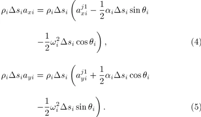
Relations between the linear accelerations of the rst joint of each link and its mass center are as follows:
isiaxi= isi
aj1xi 1
2isisin i 1
2!i2sicos i
; (4)
isiayi= isi
aj1yi+12isicos i
1
2!2isisin i
: (5)
Equations 6 and 7 indicate the relations between the linear accelerations of the two consecutive joints of each link.
aj2xi= aj1xi isisin i !i2sicos i; (6)
Furthermore, the consistency equations at each joint are as follows:
aj2xi= aj1xi+1; aj2yi= aj1yi+1;
Fxij2= Fxi+1j1 ; Fyij2= Fyi+1j1 : (8) The boundary conditions of the chain (string) include xed starting and free end points. Therefore, zero acceleration and force are attributed to the starting and end points, respectively.
aj1x1= aj1y1= 0; (9)
Fj2
xn= Fynj2= 0: (10)
To study the chain kinematics, it is enough to calculate the angular acceleration of each link (i) and there is no
need to calculate the other unknowns such as the forces and linear accelerations components. After eliminating the forces and linear accelerations and solving the linear system of equations, the angular accelerations are calculated exactly. Then, the angular velocity (!i)
and the angle change of each link (i) are obtained
as follows: !t+t
i = !it+ it; (11)
i= 1=2it2+ !it: (12)
Starting from the rst link toward the end one, the new positions of joints (j + 1) are obtained by adding the angle change of each link, with respect to the calculated position of the previous joint (j).
The solution starts with an initial guess such that the duct's main characteristics (e.g., length and inlet or outlet area) are known and xed. In this method, one of the joints coordinates (say x) is xed.
xt+t
j = xtj; (13)
yt+t
j+1 = yt+tj + sisin(i+ i): (14)
In the case of a high curved duct such as an elbow, the mean length of the duct is known. Therefore, Equation 15 is used instead of Equation 13.
xt+t
i+1 = xt+ti + sicos(i+ i): (15)
Applying Pressure Dierence to the String In order to converge the FSA design procedure, it is very important as to how the dierence between TPD and CPD is applied to the string.
In supersonic ow regimes, the ow information just transfers to the downstream. Keeping this physical phenomenon in mind, the TPD and CPD applying
to the center of each link have to be shifted to the downstream joint (Equation 16). Therefore, the inlet pressure is shifted to the rst point of the wall, and the back pressure (pback) is eliminated from the wall
pressure distribution. This procedure for subsonic ow regimes is exactly vice versa (Equation 17). In other words, back pressure is shifted to the end point of the wall and the inlet pressure is eliminated from the wall pressure distribution.
pj+1= pi; i = j = 0; n; (16)
pj = pi; i = j = 1; n + 1;
i : index of each link; j : index of each joint: (17) In subsonic ow regimes, the boundary conditions are duct inlet Mach number and outlet pressure. Therefore, at each shape modication step, the outlet pressure remains constant, while inlet pressure changes according to the pressure in the rst interior cell. As we require the string starting point to remain stationary, prst-joint must be zero. Thus, the pressure dierence
applied to the string at any other point must be gauged with respect to the pressure dierence at the rst joint. This is shown in Equation 18.
In supersonic ow regimes, pressure and Mach number are xed as inlet boundary conditions, and outlet pressure is calculated according to the end interior cell. In other words, during the shape mod-ication, inlet pressure remains constant; equal to pin. Therefore, there is no need to gauge pressure
(Equaiton 19).
pj= (pTarget(j) pTarget(1)) (pj p1);
:: j = 1; n + 1 :: pn+1= pTarget(n+1)= Pback; (18)
pj= (pj pTarget(j));
:: j = 1; n + 1 :: p1= pTarget(1) = Pinlet: (19)
The main idea of the method is that for internal supersonic ow regimes, the TPD and CPD are ap-plied along the outer and inner surface, respectively, while, for internal subsonic ow regimes, it is vice versa.
In ducts with both subsonic and supersonic ow regimes, such as a supersonic nozzle with normal shock or convergent-divergent nozzles where the ow is subsonic, the pressure dierence is calculated from Equation 18 and gauged with respect to the rst joint where the ow is supersonic; it is calculated from Equation 19. Finally, the pressure dierence applied to each link of the string is obtained from the following
equation:
p
i = (pj+ pj+1)=2; :: i = j = 1; n;
i : index of each link; j : index of each joint: (20) FSA Design Procedure
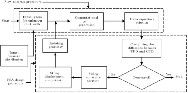
Figure 3 shows how the string equations are typically incorporated into existing ow solution procedures. The computed pressure surfaces are normally obtained from partially converged numerical solutions of the ow equations. During the iterative design procedure, as the CPD approaches the TPD, the force applied to the string gradually vanishes and, at the nal steps, the subsequent solutions of the string equations yield no changes in the duct surface coordinates.
VALIDATION
For validation of the proposed method, a given con-guration, such as a supersonic nozzle, convergent-divergent nozzle or a 90-deg bended duct, is analyzed to obtain the solid wall pressure distribution. Then, these pressure distributions are considered as our TPD for the SSD problems.
In all test cases studied here, the iterations were stopped after the residuals were reduced by 3 orders of magnitude in which residuals are dened as: Pjpj=pI.G.j j. After each geometry modication
step, the analysis code is run until the residuals were reduced by 1 order of magnitude. The residual of the analysis code is dened as the normalized changes in conserved ow variables in which the normalization is performed by the residual of the rst iteration (j(Qn+1 Qn)=QI.G.j).
Reducing the residuals 3 orders of magnitude for the design algorithm and 1 order of magnitude for the analysis code is enough to conrm the required conver-gence so that the dierence between calculated and tar-get shapes cannot be recognized. The design algorithm and analysis code show their capabilities to reduce the residuals up to 6 orders of magnitude. But, during de-sign problems, any excessive decrement of the residuals just increases the computational cost and time.
Here, the robustness of the design method is considered as the ability to use any initial guesses in each arbitrary computational grid. An ideal robust method should work well, regardless of the resolution of the computational grid and the initial guess.
Wind Tunnel Supersonic Nozzle
The rst case is an ideal supersonic nozzle (Figure 4) which is extensively used in supersonic wind tunnels. In order to verify the capability of the proposed method, the ow eld of the supersonic nozzle is analyzed and the wall pressure distribution is determined. The method should converge to this shape from an initial ar-bitrary shape if the goal is set to be the calculated (de-sired) pressure distribution. Initiating from a straight duct with a constant area section, the design program algorithm is converged only after 60 modication steps. The wall pressure distributions of the initial and nal shape are shown in Figure 5. Figure 6 shows the modication procedure from initial guess to the target shape, in which the shape modication procedure is accomplished from upstream to downstream. The inlet Mach number and pressure have been set to 1.01 and 1 bar, respectively. Overall, a computational grid of
Figure 4. Supersonic nozzle geometry with its grid.
Figure 5. Wall shape modication procedure from a parallel duct to the ideal supersonic nozzle.
Figure 6. Wall pressure distribution of initial guess and target shape of the supersonic nozzle.
40 16 is used for the analysis code, as shown in Figure 4.
Eect of Initial Guess
One of the outstanding capabilities of inverse design methods is their full independency from the initial guess. Keeping this reason in mind, a convergent duct with straight walls is considered as the initial guess for a supersonic nozzle. As shown in Figure 7, in contrast with the presence of a high dierence between initial guess and target shape, the initial guess is converged to the target shape only after 90 iterations. An interesting point which shows the capability of the method is that the ow regime at primitive modication steps includes both subsonic and supersonic regimes. In Figure 8, the
Figure 7. Wall shape modication procedure from a convergent duct to the ideal supersonic nozzle.
Figure 8. Variation of wall Mach number distribution from a convergent duct to the ideal supersonic nozzle.
variations of wall Mach number from initial guess to the target shape are shown.
Supersonic Nozzle with Normal Shock
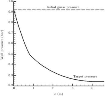
The target pressure distribution for the second valida-tion test case is obtained from the soluvalida-tion of the ow through the supersonic nozzle with normal shock with the following characteristics: Entrance Area = 0.5 m2,
Exit Area = 0.93 m2, Length = 4.6 m, Entrance Mach
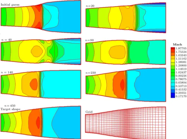
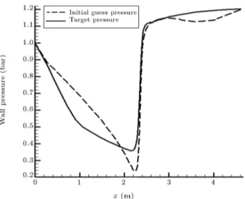
Number = 1.01, Entrance Pressure = 1 bar and Back Pressure = 1.2 bar. Because a normal shock occurs through the duct, a grid of 50 20 which is rened beside the normal shock is used, as shown in Figure 9. Figure 9 illustrates the initial guess and the evolution of the duct shape with their Mach number contour. Also, wall pressure distributions of the initial guess and target shape are shown in Figure 10. Although the inverse design of a duct with normal shock may have less application, it well presents the great capability of our design method. In Figures 11 and 12, a constant area section duct and a convergent duct are used as the initial guess for a supersonic nozzle with normal shock. As shown in these gures, since the initial guess is not a suitable one, severe shape changes occur during its evolution.
Wind Tunnel Supersonic Nozzle for M > 2 In order to study the FSA treatment in supersonic ow regimes with Mach number greater than 2, an ideal nozzle is considered as the target shape, with the following characteristics: Entrance Area = 0.14 m2,
Exit Area = 0.6 m2, Length = 1.4 m, Entrance Mach
Number = 1.1, Entrance Pressure = 1 bar and Exit Mach Number = 2.7. A grid of 40 15 shown in Figure 13a is used to analyze the ideal nozzle. The contours of the Mach number through the nozzle and wall pressure distribution of the nozzle as the TPD are shown in Figures 13b and 14, respectively. Staring from a straight divergent duct as the initial guess, the FSA is converged to the target shape after 350 modication steps, as shown in Figure 15.
Convergent-Divergent Nozzles
The other validation test case is a convergent-divergent nozzle that includes subsonic, transonic and supersonic regimes. Its TPD is obtained from the numerical analysis of this nozzle with a grid of 256 nodes, shown in Figure 16, and with the following specications: Inlet Mach Number = 0.2, Inlet Pressure = 1 bar, Back Pressure=0.5 bar and Outlet Mach Number=1.5.
Figure 10. Initial guess and target pressure distribution for supersonic nozzle with normal shock.
Figure 11. Wall shape modication from parallel duct to supersonic nozzle with normal shock.
Figure 12. Wall shape modication from straight convergent duct to supersonic nozzle with normal shock.
Figure 13. a) An ideal supersonic nozzle for M > 2 with its grid; b) Contour of Mach number through the Nozzle.
Figure 14. Wall pressure distribution of the ideal supersonic nozzle.
Numerical analysis of this nozzle presents a subsonic and supersonic region at the convergent and divergent parts, respectively. Starting from a constant area section duct as the initial guess, the inverse design algorithm converges to the convergent-divergent nozzle as the target shape after 130 evolution steps (Fig-ure 17), contrary to the high dierence between them. Figure 18 shows the initial guess and target pressure distribution.
Figure 15. Wall shape modication from straight divergent duct to the ideal supersonic nozzle.
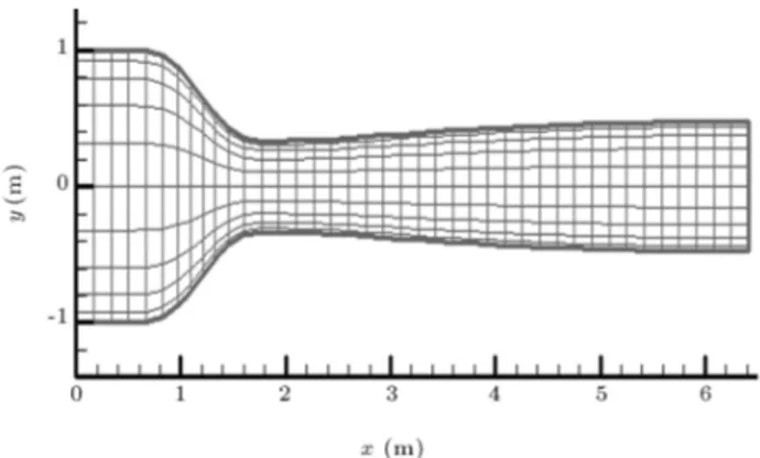
Figure 16. Convergent-divergent nozzle with its grid.
Figure 17. Wall shape modication from parallel duct to the convergent-divergent nozzle with normal shock.
Figure 18. Initial guess and target pressure distribution for convergent-divergent nozzle.
Bended Subsonic Duct with Two Unknown Walls
In all cases presented earlier in this paper and in [20], the horizontal length of the duct remains constant through the shape modication steps. In the case of a duct with a bend, the outlet section is not perpendicular to the x axis and, so, it is not possible to x the horizontal length of the duct. In such cases, instead of horizontal length, the duct centerline length is assumed known and remains constant during the evolution (Equation 15). In this case, the duct is asymmetric and, so, both upper and lower duct walls are unknown. These two walls are modeled as two strings deforming from initial guess to the target shape. During the shape modication procedure, the length of each string is modied based on the xed centerline length. If the evolution of each wall is accomplished independently, a large number of modication steps are required to converge the design algorithm, since in such cases the pressure is highly sensitive to the wall shape change. Considering a virtual string on the duct centerline with a constant length, and applying the dierence between the upper and lower pressure to the centerline string, the convergence rate of the design algorithm will be increased signicantly. In other words, in the case of ducts with two unknown walls, three strings can be modeled on the upper wall, lower wall and centerline, whereby the centerline string, as an auxiliary string, causes the duct shape modication to speed up. The pressure dierence applied to the centerline string is obtained from the following equation for each link:
p
In this part, we want to redesign a duct with a 90
bend. The TPD (Figure 19) for this validation test case is obtained from the numerical analysis of the ow through it, with a grid of 35 10 nodes. Inlet Mach number and back pressure are considered 0.5 and 1, respectively. Figure 20 illustrates the initial guess and the evolution of the shape after 80, 200, 400 and 1000 modication steps. As shown in this gure, since the initial guess is not a suitable one, severe shape changes occur during its evolution.
Bended Supersonic Duct with Two Unknown Walls
A supersonic 45-deg bended duct with a divergent section was considered as a target shape, and its pressure distribution, shown in Figure 21, was obtained
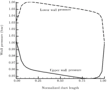
Figure 19. Pressure distribution along the lower and upper wall of 90-deg bended duct.
Figure 20. Evolution of the 90-deg bended duct during the design process.
from numerical analysis. Inlet Mach number and inlet pressure set to 2 and 1 bar, respectively, and a grid of 35 10 nodes is used for numerical analysis. Figure 22 illustrates the initial guess and the evolution of the shape after 60, 150 and 400 modication steps. As shown in this gure, since the initial guess is not a suitable one, it gets the target shape after 400 steps. DESIGN EXAMPLES
Design of S-Shaped Ducts
Using the inverse design method, one can nd the appropriate geometry for S-shaped ducts used as dif-fusers in the intake section of jet engines. Because of considerable adverse pressure gradients along their walls, the possibility of ow separation is very high
Figure 21. Pressure distribution along the lower and upper wall of 45-deg divergent bended duct.
Figure 22. Evolution of the 45-deg divergent bended duct during the design process.
in such ducts. Besides, small regions may exist near the inlet, in which the Mach number exceeds from 1 and the ow regime is supersonic. Although the adverse pressure gradients are inevitable in such ducts, one looks for S-shaped ducts without overshoot and undershoot in their wall pressure proles, to avoid shock waves and to reduce ow separation possibilities. Here, we consider an arbitrary S-shaped diuser as the initial guess with an inlet area of 0.9, a length of 6 and an area ratio of 1.5. The upper and lower walls of the initial S-shaped diuser are considered as two second order polynomials. The initial S-shaped diuser with its grid for the numerical analysis is shown in Figure 23. The inlet Mach number and back pressure are set to 0.84 and 1.4, respectively. The initial pressure distribution is illustrated in Figure 24. After modifying the initial pressure distribution, the TPD is obtained in such a way that undershoots and overshoots are removed from the initial pressure distribution and the pressure coecient is increased, as shown in Figure 24. After 1500 shape modication steps, the initial diuser converges to the target shape, as shown in Figure 25. Figure 26 compares the Mach
Figure 23. Initial S-shape diuser with its grid.
Figure 24. Initial pressure distribution and TPD for design of S-shape diuser.
Figure 25. The initial guess and target shape for S-shape diuser.
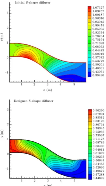
Figure 26. Contour of Mach number through the initial and designed S-shape diuser.
number contour of the modied S-shaped diuser with that of the initial S-shaped diuser. As opposed to the initial S-shaped diuser, the contour of the Mach number in the modied S-shape diuser decreases from 0.88 to 0.45, monotonically, with no overshoot and, thus, the ow remains subsonic in the entire domain.
In order to study the grid size eect on the designed shape, the S-shape diuser, as a complicated case, is redesigned for three grids (24 9, 32 12 and 40 15) with the same TPD in Figure 24. Figure 27 compares two designed shapes. The shape related to the 40 15 grid is not shown in Figure 27, because it coincides with the shape corresponding to the 32 12 grid.
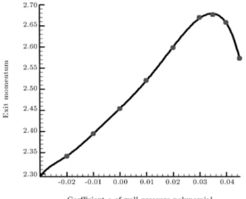
Supersonic Nozzle Design with Maximum Thrust
In this part, designing a supersonic nozzle with maxi-mum thrust under an inlet and outlet specied pressure is in mind. To do this, some dierent wall pressure distributions as TPDs are considered, and the nozzles equivalent to these TPDs are obtained using the inverse design code. Then, the thrust of each nozzle is calculated from the numerical analysis. In Figure 28a, four TPDs, with respect to Equation 22, are shown. The nozzles equivalent to these TPDs are shown in Figure 28b.
P (x) = ax2+Pback Pin
L + aL
x + Pin: (22)
Figure 29 shows the calculated thrust versus coe-cient (a). As seen in this gure, the thrust is a maximum value, as the coecient (a) is 0.035.
Figure 27. The grid study for design of S-shape diuser.
Figure 28. a) Four TPDs for design of supersonic nozzles; b) Four designed supersonic nozzles.
Figure 29. Calculated thrust versus dierent coecients (a).
BOUNDARY CONDITION EFFECTS
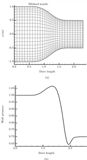
In all test cases, in order to converge the design algorithm for subsonic ow regimes, inlet Mach number and back pressure are considered as the boundary conditions. In the FSA method, there is no dierence between the uniform and non-uniform boundary con-dition at the inlet or outlet. The authors' experience indicated that inlet pressure and back pressure as the boundary conditions are not compatible with FSA, be-cause the free end point of the string is not compatible with the xed inlet and outlet pressure. In other words, if both inlet and outlet pressures are xed, both the inlet area and outlet area must be xed, and the end of the string cannot be free. In order to show the boundary condition eect, a Michael nozzle, shown in Figure 30a is considered as the target shape. The wall pressure distribution of the Michael nozzle obtained
Figure 30. a) Geometry of Michael nozzle with its grid; b) wall pressure distribution.
from numerical analysis is illustrated in Figure 30b. Figure 31a shows that FSA converges to a Michael nozzle with an inlet Mach boundary condition after 100 iterations, whereas it diverges with a pressure inlet boundary condition (Figure 31b).
CONCLUSIONS
The FSA design procedure is incorporated into an existing Euler code with the AUSM method. The FSA turns the inverse design problem into a uid-solid in-teraction scheme that is a physical base. The method is quick converging and can eciently utilize ow analysis codes as a black box. The results show that the method can be very promising in duct and other ow conduit designs for both subsonic and supersonic regimes. In
Figure 31. a) Modication steps of Michael nozzle wall from the initial guess to the target shape versus inlet Mach boundary condition, b) Divergence procedure of Michael nozzle wall versus inlet pressure boundary condition.
the case of unsymmetrical ducts with two unknown walls, the FSA is modied to increase the convergence rate signicantly. Also, the results show that FSA is compatible with inlet Mach number and back pressure boundary conditions for subsonic ow regimes. NOMENCLATURE
a linear acceleration (m.s 2)
AUSM Advection Upstream Splitting Method CPD Current Pressure Distribution on the
wall
F force vector (N)
FSA Flexible String Algorithm
n number of shape modications
n number of links
pi pressure calculated at cell center near
the wall (Pa)
Q sum of the conserved ow variables such as , u, v, e in Euler equations
SSD Surface Shape Design
t time (s)
TPD Target Pressure Distribution
x x position of joints (m), x coordinate y y position of joints (m), y coordinate
w width of duct (m)
dierence
s link length (m)
p
i pressure dierence applied to each link
(Pa)
pi dierence between TPD and CPD at
each link (Pa)
angular acceleration (rad.s 2)
" convergence criterion
link angle (deg)
mass per unit length (kg.m 1)
! angular velocity (rad.s 1)
Subscripts
i links index
j joints index
max maximum
x x component
y y component
Superscripts
I.G. initial guess
j1 starting point of each link j2 end point of each link
n iteration number at analysis code t + t related to updated geometry t related to current geometry REFERENCES
1. Ghadak, F. \A direct design method based on the Laplace and Euler equations with application to in-ternal subsonic and supersonic ows", Ph.D Thesis, Sharif University of Technology, Aero Space Depart-ment, Iran (2005).
2. Stanitz, J.D. \Design of two-dimensional channels with prescribed velocity distributions along the duct walls", Technical Report 1115, Lewis Flight Propulsion Laboratory (1953).
3. Stanitz, J.D. \General design method for three-dimensional, potential ow elds", I-Theory. Technical Report -3288, NASA (1980).
4. Stanitz, J.D. \A review of certain inverse methods for the design of ducts with 2- or 3-dimensional potential ows", Proceedings of the Second International Confer-ence on Inverse Design Concepts and Optimization in Engineering Sciences (ICIDES-II), The Pennsylvania State University, University Park, PA (Oct. 26-28 1987).
5. Zanetti, L. \A natural formulation for the solution of two-dimensional or axis-symmetric inverse problems", International Journal for Numerical Methods in Engi-neering, 22, pp. 451-463 (1986).
6. Ashrazadeh, A., Raithby, G.D. and Stubley, G.D. \Direct design of ducts", Journal of Fluids Engineer-ing, Transaction ASME, 125, pp. 158-165 (2003). 7. Cheng, Chin-Hsiang and Wu, Chun-Yin. \An approach
combining body tted grid generation and conjugate gradient methods for shape design in heat conduction problems", Numerical Heat Transfer, Part B, 37(1), pp. 69-83 (2000).
8. Jameson, A. \Optimal design via boundary control", Optimal Design Methods for Aeronautics, AGARD, pp. 3.1-3.33 (1994).
9. Kim, J.S. and Park, W.G. \Optimized inverse design method for pump impeller", Mechanics Research Com-munications, 27(4), pp. 465-473 (2000).
10. Dedoussis, V., Chaviaropoulos, P. and Papailiou, K.D. \Rotational compressible inverse design method for two-dimensional, internal ow congurations", AIAA Journal, 31(3), pp. 551-558 (1993).
11. Demeulenaere, A. and Braembussche, R. van den, \Three-dimensional inverse method for turbomachi-nary blading design", ASME Journal of Turbomachi-nary, 120(2), pp. 247-255 (1998).
12. De Vito, L. and Braembussche, R.V.D \A novel two-dimensional viscous inverse design method for turbo-machinery blading", Transactions of the ASME, 125, pp. 310-316 (2003).
13. Braembuussche, R.V.D. and Demeulenaere, A. \Three dimensional inverse method for turbomachinery blad-ing design", Journal of Turbomachinery, 120, pp. 247-255 (1998).
14. Leonard, O. and Braembussche, R. \A two-dimensional Navier stokes inverse solver for compressor and turbine blade design", Proceeding of the IMECH E part A Journal of Power and Energy, 211, pp. 299-307 (1997).
15. Henne, P.A. \An inverse transonic wing design method", AIAA Paper, 80-0330 (1980).
16. Volpe, G. \Inverse design of airfoil contours: Con-straints, numerical method applications", AGARD, Paper 4 (1989).
17. Barger, R.L. and Brooks, C.W. \A streamline curva-ture method for design of supercritical and subcritical airfoils", NASA TN D-7770 (1974).
18. Campbell, R.L. and Smith, L.A. \A hybrid algorithm for transonic airfoil and wing design", AIAA Paper, pp. 87-2552 (1987).
19. Bell, R.A. and Cedar, R.D. \An inverse method for the aerodynamic design of three-dimensional aircraft engine nacelles", Dulikravich, pp. 405-17 (1991). 20. Malone, J.B., Narramore, J.C. and Sankar, L.N. \An
ecient airfoil design method using the Navier-Stokes equations", AGARD, Paper 5 (1989).
21. Nili-Ahmadabadi, M., Durali, M., Hajilouy, A. and Ghadak, F. \Inverse design of 2D subsonic ducts using exible string algorithm", Inverse Problems in Science and Engineering, 17(8), pp. 1037-1057 (2009). 22. Liou, M.-S. \Ten years in the making-AUSM-family",
AIAA Paper, 2001-2521 (2001).
BIOGRAPHIES
Mahdi Nili-Ahmadabadi is a teacher of Mechanical Engineering at Isfahan University of Technology. In Feb. 2010, he graduated from Sharif University of Technology in Iran with a PhD in Mechanical Engi-neering. He obtained a BS and MS at Sharif University of Technology and Isfahan University of Technology,
respectively. He has published 5 scientic papers in ISI journals until now. His research interests are: aerodynamic design, uid mechanics, heat transfer, turbomachines & gas turbines.
Mohammad Durali is a Professor of Mechanical Engineering at Sharif University of Technology. He graduated with a PhD in Aerospace Engineering from Massachusetts Institute of Technology (MIT) in the USA (1980). He obtained a BS and MS at Sharif University of Technology in Iran and Massachusetts Institute of Technology (MIT) in the USA, respectively. He has published more than 20 scientic papers in ISI journals and presented more than 100 papers at dierent conferences. His research Interests are: design and automation, system dynamics & modeling, propulsion systems.
Ali Hajilouy-Benisi is an Associate Professor of Mechanical Engineering at Sharif University of Tech-nology. He graduated with a PhD in Mechanical Engineering from Imperial College, London, in the UK (1993). He obtained a BS and MS at Sharif University of Technology in Iran and Birmingham University in the UK, respectively. He has published more than 10 scientic papers in ISI journals and presented more than 50 papers at dierent confer-ences. His research Interests are: turbomachines, gas turbines, measurement, turbochargers & turbocharg-ing.
Farhad Ghadak is an Assistant Professor of Aerospace Engineering at Imam Hossein University. He graduated with a PhD in Aerospace Engineering from Sharif University of Technology in Iran in 2007. He obtained a BS and MS at Tehran University and Shiraz University, respectively. He has published 6 scientic papers in ISI journals and presented more than 10 papers at dierent conferences. His research interests are: CFD, inverse design, wind tunnels, aerodynamics & ight control.