Bridge Construction for New Broad Guage Line
Md Ihtesham Ul Hasan, Sunandan Reddy,K.MythiliAurrora’s Scientific Tehnological & Research Acadamy (Bandlaguda,Hyd)
[email protected]ABSTRACT:- From the moment human started exploring he started to travel across the world after the world- war II due to the industrial revolution these became even intense to travel for overseas human used only ships but to travel in his own country he made only slow means of transport like bullock cart which not even safe. Then human started thinking about to decrease his travel time and increase his own safety then they invented railway service which much safe, time conserving due to the low in expenditure to travels by trains many middle class and lower middle class people depended on it a lot and it even cheap to transfer the good for long distance at low price with lead to growth of importance of railway services. Construction of new railway is really a tough task which involve in consideration of several parameters and several unexpected conditions. When the track is properly aligned it is a very good means of source of revenue to government and also good means transportation for public. At both the execution of construction work and even the maintenance it provide huge opportunity of employment.
1. INTRODUCTION
1.1 Introduction to Railway bridges:
Our mini project is totally concreted on railway bridge construction. In general rail way track is aligned in most economical way but sometimes railway line come across several obligatory points like holy places, schools, areas with high land value and even tributaries of river or streams in such cases bridges and designed and constructed. It is done by following methods. At first and foremost step followed align the railway line is topographical survey. In this part a topographical map is used to
check the possibilities of alignment of track and from that the best possible path is finalized. Then the field test is carried out to get a clear idea about the site condition. Which consist of total station survey for central line alignment, leveling works which also results in finding the RL at different point and even useful to transfer them to required location to avoid obstruction in visibility, then followed by soil exploration works which involves in lab work.
Once these work is done the next procedure of work continues i.e. land acquisition as a part of these the railway authority make contact with local revenue department officials for land purchase from the respective owners. Then it is followed by earth work where excavation work for different types of foundation, as we know different methods of foundations are followed based on the ground condition. When the main excavation work is done the bridge construction starts ex foundation, piers to get all the piers in exact alignment total station is used. Once the piers are done then the bed block marking is done over which precast girders are place. All these processes go into the sub tenders form. When the construction of bridges is done, sleepers are placed at the site for the Next process i.e. track alignment along the center marked line.
2. TYPES OF BRIDGES
2.1Arch bridges
resist the vertical and horizontal components of these thrusts. If the supports spread apart the arch falls down. The Romans knew all about this. Traditionally, arch bridges were constructed of stone, brick or mass concrete since these materials are very strong in compression and the arch could be configured so that tensile stresses did not develop. Modern concrete arch bridges utilize prestressing or reinforcing to resist the tensile stresses which can develop in slender arch rings. The shape attracted the attention of many of the early pioneers of concrete construction. In 1930, Freyssinet was responsible for a spectacular arched bridge at Plougastel in France and three years later, Swiss engineer, Robert Maillart created the famously elegant Schwandbach bridge in which slender cross-walls tie the arch to the horizontally curved roadway.
2.2 Reinforced slab bridges
For short spans, a solid reinforced concrete slab, generally cast in-situ rather than precast, is the simplest design. It is also cost-effective, since the flat, level soffit means that false work and formwork are also simple. Reinforcement, too, is uncomplicated. With larger spans, the reinforced slab has to be thicker to carry the extra stresses under load. This extra weight of the slab itself then becomes a problem, which can be solved in one of two ways. The first is to use pre-stressing techniques and the second is to reduce the deadweight of the slab by including 'voids', often expanded polystyrene cylinders. Up to about 25m span, such voided slabs are more economical than pre-stressed slabs.
2.3Beam and slab bridges
Beam and slab bridges are probably the most common form of concrete bridge in the India today, thanks to the success of standard precast pre-stressed concrete beams developed originally by the Pre-stressed Concrete Development Group (Cement & Concrete Association) supplemented later by alternative designs by others, culminating in the Y-beam introduced by the Pre-stressed Concrete Association in the late 1980s. They have the virtue of simplicity, economy, wide availability of the standard
sections, and speed of erection. The precast beams are placed on the supporting piers or abutments, usually on rubber bearings which are maintenance free. An in-situ reinforced concrete deck slab is then cast on permanent shuttering which spans between the beams. The precast beams can be joined together at the supports to form continuous beams which are structurally more efficient. However, this is not normally done because the costs involved are not justified by the increased efficiency. Simply supported concrete beams and slab bridges are now giving way to integral bridges which offer the advantages of less cost and lower maintenance due to the elimination of expansion joints and bearings.
2.4 Internal bridges
One of the difficulties in designing any structure is deciding where to put the joints. These are necessary to allow movement as the structure expands under the heat of the summer sun and contracts during the cold of winter. Expansion joints in bridges are notoriously prone to leakage. Water laden with road salts can then reach the tops of the piers and the abutments, and this can result in corrosion of all reinforcement. The expansive effects of rust can split concrete apart.In addition, expansion joints and bearings are an additional cost so more and more bridges are being built without either. Such structures, called 'integral bridges', can be constructed with all types of concrete deck. They are constructed with their decks connected directly to the supporting piers and abutments and with no provision in the form of bearings or expansion joints for thermal movement. Thermal movement of the deck is accommodated by flexure of the supporting piers and horizontal movements of the abutments, with elastic compression of the surrounding soil.
TYPES OF FOUNDATIONS
5.1 Open foundation
obstructions in the ground. An open caisson that is used in soft grounds or high water tables, where open trench excavations are impractical, can also be used to install deep manholes, pump stations and reception/launch pits for micro tunneling, pipe jacking and other operations.
A caisson is sunk by self-weight, concrete or water ballast placed on top, or by hydraulic jacks. The leading edge (or cutting shoe) of the caisson is sloped out at a sharp angle to aid sinking in a vertical manner; it is usually made of steel. The shoe is generally wider than the caisson to reduce friction, and the leading edge may be supplied with pressurized bentonite slurry, which swells in water, stabilizing settlement by filling depressions and voids. An open caisson may fill with water during sinking. The material is excavated by clamshell excavator bucket on crane.
The formation level subsoil may still not be suitable for excavation or bearing capacity. The water in the caisson (due to a high water table) balances the up thrust forces of the soft soils underneath. If dewatered, the base may "pipe" or "boil", causing the caisson to sink. To combat this problem, piles may be driven from the surface to act as:Load-bearing walls, in that they transmit loads to deeper soils.
Anchors, in that they resist floatation because of the friction at the interface between their surfaces and the surrounding earth into which they have been driven. H-beam sections (typical column sections, due to resistance to bending in all axes) may be driven at angles "raked" to rock or other firmer soils; the H-beams are left extended above the base. A reinforced concrete plug may be placed under the water, a process known as Tremie concrete placement. When the caisson is dewatered, this plug acts as a pile cap, resisting the upward forces of the subsoil.
Box foundation
A box caisson is a prefabricated concrete box (it has sides and a bottom); it is set down on prepared bases. Once in place, it is filled with concrete to become part of the permanent works, such as the foundation for a bridge pier. Hollow concrete structures float (seeWWII concrete ships), so a box caisson must be
ballasted or anchored to prevent this phenomenon until it can be filled with concrete (indeed, elaborate anchoring systems may be required in tidal zones); adjustable anchoring systems, combined with a GPS survey, allows engineers to position a box caisson with pinpoint accuracy. Well foundation
This work consists of construction of well foundation, taking it down to the founding level through all kinds of sub-strata, plugging the bottom, filling the inside of the well, plugging the top and providing a well cap in accordance with the details shown on the drawing. Well may have a circular, rectangular, or D-shape in plan and may consist of one, two or more compartments in plan.
Well Components & their Function
In brief the function of various elements is as follows:
5.3.1 Cutting edge
The mild steel cutting edge shall be made from structural steel sections. The cutting edge shall weigh not less than 40 kg per meter length and be properly anchored into the well curb, as shown in the drawing. When there are two or more compartments in a well, the bottom end of the cutting edge of the inner walls of such wells shall be kept at about 300 mm above that of outer walls.
5.3.2 Curb
The well curb may be precast or cast-in-situ. Steel formwork for well curb shall be fabricated strictly in conformity with the drawing. The outer face of the curb shall be vertical Steel reinforcements shall be assembled as shown on the drawings. The bottom ends of vertical bond rods of staining shall be fixed securely to the cutting edge with check nuts or by welds.The formwork on outer face of curb may be removed within 24 hours after concreting. The formwork on inner face shall be removed after 72 hours. It is made up of reinforced concrete using controlled concrete of grade M-35.
5.3.3 Steining
those shown on the drawings. The formwork shall preferably be of M.S. sheets shaped and stiffened suitably. In case timber forms are used, they shall be lined with plywood or M.S. sheets. The steining of the well shall be built in one straight line from bottom to top such that if the well is tilted, the next lift of steining will be aligned in the direction of the tilt. After reaching the founding level, the well steining shall be inspected to check for any damage or cracks
5.3.4 Bottom plug
Its main function is to transfer load from the steining to the soil below. For bottom plug, the concrete mix shall be design (in dry condition) to attain the concrete strength as mentioned on the drawing and shall contained 10 per cent more cement than that required for the same mix placed dry.
5.3.5 Sand filling
Sand filling shall commence after a period of 3 days of laying of bottom plug. Also, the height of the bottom plug shall be verified before starting sand filling. Sand shall be clean and free from earth, clay clods, roots, boulders, shingles, etc. and shall be compacted as directed. Sand filling shall be carried out up to the level shown on the drawing or as directed by the Engineer.
5.3.6 Intermediate plug
The function of the plug is to keep the sand filling sandwiched & undisturbed. It also act as a base for the water fill, which is filled over it up to the bottom of the well cap.
5.3.7 Top plug
After filling sand up to the required level a plug of concrete shall be provided over it as shown on the drawing, It at least serves as a shuttering for laying well cap.
5.3.8 Reinforcement
It provides requisite strength to the structure during sinking and service.
5.3.9 Well cap
It is needed to transfer the loads and moments from the pier to the well or wells below. A reinforced cement concrete well cap will be provided over the top of the steining in accordance with the drawing. Formwork will be prepared conforming to the shape of well cap. Concreting shall be carried out in dry
condition. A properly designed false steining may be provided where possible to ensure that the well cap is laid in dry conditions
After water filling, pre-cast RCC slabs shall be placed over the RCC beams as per the drawings, as non-recoverable bottom shuttering for well cap. Initially built false wall shall act as outer shuttering for well cap casting. In case, there is no false wall, then steel shuttering is to be put from outer side.
For well Steining and well cap shuttering, permissible tolerances are as follows:
-Variation in dimension
: +50 mm to – 10mm
Misplacement from specified
Position in Plan: 15mm
Variation of levels at the top : +/- 25mm Depth of Well Foundation
As per I.R.C. bridge code, the depth of well foundation is to be decided on the following considerations:
The minimum depth of foundation below H.F.L should be 1.33D, where D is the anticipated max. Depth of scour below H.F.L depth should provide proper grip according to some rational formula.The maximum bearing pressure on the subsoil under the foundation resulting from any combination of the loads and forces except wind and seismic forces should not exceed the
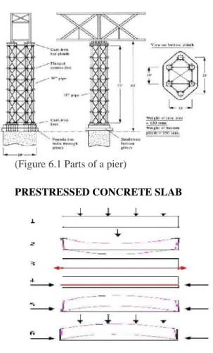
Pier construction
(Figure 6.1 Parts of a pier)
PRESTRESSED CONCRETE SLAB
Figure 7.1 Pre-stressed slab
Pre-stressed concrete is a method for overcoming concrete's natural weakness in tension. It can be used to produce beams, floors or bridges with a longer span than is practical with ordinary reinforced concrete. Pre-stressing tendons (generally of high tensile steel cable or rods) are used to provide a clamping load which produces a compressive stress that balances the tensile stress that the concrete compression member would otherwise experience due to a bending load. Traditional reinforced concrete is based on the use of steel reinforcement bars, rebars, inside poured concrete.
Pre-tensioned concrete is cast around already tensioned tendons. This method produces a good bond between the tendon and concrete, which both protects the tendon from corrosion and allows for direct transfer of tension. The cured concrete adheres and bonds to the bars and when the tension is
released it is transferred to the concrete as compression by static friction. However, it requires stout anchoring points between which the tendon is to be stretched and the tendons are usually in a straight line. Thus, most pre-tensioned concrete elements are pre-fabricated in a factory and must be transported to the construction site, which limits their size. Pre-tensioned elements may be balcony elements, lintels, floor slabs, beams or foundation piles. An innovative bridge construction method using pre-stressing is the stressed ribbon bridge design.
TYPES OF BRIDGE CONSTRUCTION MACHINERIES
11.1 Construction machineries
The various machineries for constructing bridges are:
Bridge Crane Gantry Crane Floating Crane
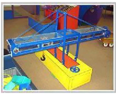
11.1.1 Bridge
cranes:-Figure 11.1 Bridge crane
Bridge crane is a heavy machinery that is designed to build or fix a bridge. It operates on two tracks and has four way horizontal movement. Bridge cranes cover rectangular area and can be floor supported or hung from the ceiling. The main components of bridge cranes are bridge, trolley, hoist drum, hoist cable, hoist block, hook bumpers, pendant and limit switches. On-off switch is on control pendant for taking emergency steps, in the event of failure of any of the control-panels.
the girders. For high speeds and heavy services too, double girder bridge cranes are very useful. In bridge crane rigid box girder construction and durable trolley design are well suited for heavy service applications.
11.1.2 Gantry cranes
Figure 11.2 Gantry crane
Gantry cranes are those cranes which are generally used for moving heavy loads. They are a common type of portable material handling equipment used in job station or secondary task areas. Gantry cranes are quite similar to overhead cranes except that the bridge which carries trolley is rigidly supported on two or more legs running.
11.1.2.1 Gantry crane sizes and
marking:-Though gantry cranes are known for its huge models but, there happen to be smaller cranes as well that are found in small industries and warehouses etc. The cranes are available in both, adjustable as well as fixed height. Its making too is either of steel or aluminum, depending upon the application of the crane. Each gantry crane is designed with two upright beams and a cross beam. It has an A-frame shaped set of two legs with wheels beneath to render maximum mobility and portability.
11.1.2.2 Types of gantry
cranes:-Gantry cranes can be of different range like single girder, double girder, double leg, single leg, and cantilever styles for indoor or outdoor service. It is also available in fixed height steel and adjustable steel. Gantry crane is an economical device for lifting materials anywhere in a facility. Gantry cranes are also supplied with four roller-bearing steel wheels for easy maneuverability.
Uses of gantry
cranes:-Gantry cranes or bridge cranes are useful machinery which find its application in constructing bridges. Lifting heavy industrial devices, lifting containers in seaports, and are ideal for use in air craft, automotive, and marine repair shops.
REFERENCES
1. Mitchell, J.K., and Soga, K. (2005) Fundamentals of soil behavior, Third edition, John Wiley and Sons, Inc., ISBN 978-0-471-46302-7.
2. Santamarina, J.C., Klein, K.A., & Fam, M.A. (2001). Soils and Waves: Particulate Materials Behavior, Characterization and Process Monitoring. Wiley. ISBN 978-0-471-49058-6.
3. http://en.wikipedia.org/wiki/Rail_transport_in_India .
4. Powrie, W., Spon Press, 2004, Soil Mechanics - 2nd ed ISBN 0-415-31156-X
5. A Guide to Soil Mechanics, Bolton, Malcolm,Macmillan Press, 1979. ISBN 0-333-18932-0
6. Fang, Y., Spon Press, 2006, Introductory Geotechnical Engineering
7. Lambe, T. William & Robert V. Whitman. Soil Mechanics. Wiley, 1991; p. 29. ISBN 978-0-471-51192-2
8. Holtz, R.D, and Kovacs, W.D., 1981. An Introduction to Geotechnical Engineering. Prentice-Hall, Inc. page 448
9. Wood, David Muir, Soil Behavior and Critical State Soil Mechanics, Cambridge University Press, 1990, ISBN 0-521-33249-4
10. Disturbed soil properties and geotechnical design, Schofield, Andrew N.,Thomas Telford, 2006. ISBN 0-7277-2982-9
11. ASTM Standard Test Methods for Minimum Index Density and Unit Weight of Soils and Calculation of Relative Density. http://www.astm.org/Standards/D4254.html 12. Cedergren, Harry R. (1977),