1
Project Development Plan
Roverwerx A.R.M.
IRP
Santa Clara University
Richard Rasay
2
TABLE OF CONTENTS
Introduction………1
Software Design……….3
Robot-Side Application……….5
Client-Side Application……….7
Current Status………9
3
INTRODUCTION
Abstract
As a part of a Mechanical Engineering design project (1999-2000), a land-based rover (Roverwerx) capable of negotiating large obstacles was designed and created to be a part of an ongoing venture in the Intelligent Robotics Program (IRP) at Santa Clara University. In continuing the design of Roverwerx, a proposed mechanical arm subsystem is to be added with specific requirements of control through an Internet interface. The task of implementing the mechanical arm subsystem consists of, mechanical and computer engineering aspects, which will proceed to be assumed by a team of three Mechanical Engineers and a single Computer Engineer.
System Design
The mechanical arm system is designed to be mounted on Roverwerx with the capacity to pick up and grasp different objects. The mechanical structure uses three arm joints, a pivoting base, and a grasping mechanism (Figure 1). The three joints reside at the base, midpoint, and at the foot of the grasping mechanism. Each joint will be maintained with motors controlled by a micro-controller and driver circuitry, which includes joint sensors that provide the arm’s orientation.
4
Figure
1-Mechanical Arm
Along with the arm, an array of data collecting sensors and a motion control subsystem are a part of the global system. The collaboration of the various subsystems requires a central processor that will collectively manage individual operations. A solution to the need of high computing power, a laptop will sit onboard Roverwerx to act as the system’s central processor and will be interfaced with each subsystem via serial communication. The laptop solution is desirable because of the capabilities to act as a preconfigured for communication through TCP/IP.
Responsibilities
Separating the arm subsystem and the Internet and laptop interfaces makes distinctions between Mechanical Engineering and Computer Engineering aspects of the project. Focus of the Mechanical Engineering portion consists of implementing the mechanical arm, which includes the structure, circuitry, and micro-controller specifics.
5
Interfacing the arm control, overall motion control, and data communications is assumed as the focus of the Computer Engineering portion of the system.
SOFTWARE DESIGN
Communication through the Internet and the use of TCP/IP provides a
considerable amount of freedom when the issue of control and passing data arises. The ability to communicate and send data over TCP/IP presents the opportunity to remove an operator from an on-site location and sustain control from any location around the world.
System Software Requirements
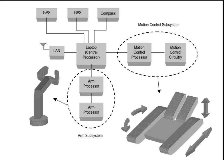
Providing a software system capable of transmitting and receiving data, while being able to complete complex computations is essential due to the intricate system aboard the rover. Data must be sent to the robot system and then translated in order to successfully complete an operation, which requires that the overall system have the ability to receive data without hindrance. By including data sensors, system sensors, and video capture devices used to provide the operator with important information requires that the system be able to compute and transmit streams of data (Figure 2). Along with the capability to transmit, receive and compute data, issues of security maintenance arise.
6
Motion Control Subsystem
Arm Subsystem
Figure 2-Roverwerx System Including Subsystems
Communication Solution-DataTurbine
With the kinds of functional requirements of the control system, a communication solution is provided through the use of a commercial software package called ‘Ring Buffered Network Bus DataTurbine’ (RBNB DataTurbine). The DataTurbine acts as a central point of contact where a number of applications can send and store data to be routed (Figure 3). Data can be set to travel in real-time or a request/response mode from one point to another, one point to many, many points to one, and can be mirrored to allow
Motion Control Processor Motion Control Circuitry LAN (Central Laptop
Processor)
GPS Compass
Arm Processor
Arm Processor GPS
7
numerous data paths. The DataTurbine also provides a system for high-speed data streaming, which betters speeds of 10MB/sec and 1000 fames/sec
(http://outlet.creare.com/rbnb/). With the use of Java and TCP/IP, the DataTurbine can run on various operating systems or can be accessed through the Internet through Java servlets being run on a server. The capability to coordinate the communication capability of the DataTurbine and the data computation provides a robust solution for control over the rover.
Figure 3-Ring Buffer Network Bus DataTurbine Data Path
ROBOT-SIDE APPLICATION
The number of systems and data collecting sensors on the Roverwerx system requires that the central processor have the capability to complete and manage various tasks. With the ability to organize data communication, an application can be created along side the DataTurbine to process the kinds of computations needed.
8
Onboard Processing
On the robot-side, the central processor is responsible for sending the proper control data to the motion control and arm subsystems as well as calculate and return the state of those subsystems to the operator. The arm subsystem accepts control data and through the use of joint sensors, the orientation of the arm is calculated and returned to the operator. Along with the arm, the motion control subsystem and data collection sensors require that the central processor have the capability to coordinate multiple tasks. The DataTurbine application interface (API) is provided for Java, which allows an
application to be built that makes use of Java’s capacity for multi-threading providing a means to manage the various processes. With the capability to organize various
processes, an application for autonomy can be built on the coordination management layer (Figure 4).
Figure 4-Robot Software Architecture
The control data that is received by the system processor is sent to the micro-controller through the serial port using the Java Communications API (COMM API). By
OS
Autonomy Application
Coordination Application
9
using the COMM API, the central processor can communicate with each subsystem and manage the operation of the overall system.
Data Communication-Rover to Operator
There are two of types of data communication modes that are required to pass to an operator in order to assume proper control over Roverwerx. The different types of data communication include subsystem states, data collection sensor information, and images to provide the operator with a view of the terrain being traversed. In case of the subsystem states, a request/response type communication is required where an operator sends data and the state of the subsystem is returned. For the data collection sensors and the image capture, a data stream is needed to provide the operator with the information used to maintain control of the rover. The robot application must have the capability to receive requests for manipulation while being able to send streams of data to the operator.
CLIENT-SIDE APPLICATION
In an on-site control situation, an operator relies on the capacity of sight to enable the manipulation over the rover, where this ability is removed in remote control. For the application of remote control, the operator must be provided with the capacity to “see” what the rover is doing at all times as well as command the actions of the rover.
10
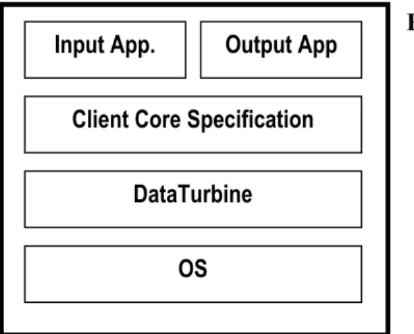
Figure 5-Operator/Client Software Architecture
Data Communication
The client side application does not assume the kind of responsibility that the robot-side does because the nature of control relies feedback. With the removal of a direct-line-of-site, the operator still only needs to send control data to the rover. The important factor to the client (operator) is being able to receive information that assumes the sense of sight. For the client, two processes are required to send control data via a request/response mode of communication and to receive information for “sight” through a streaming mode of communication. To be built on the client data communication layer, an input and output layer adds the opportunity to use different input control devices and the use of different feedback outputs from the robot (Figure 5).
CURRENT STATUS
Already implemented is, a prototype subsystem for motion control, which was demonstrated at the 2000 University Space Systems Symposium held in Hilo, Hawaii (November 11-14). The motion control system uses a simple micro-controller (Parallax BASIC Stamp II) and a motor driver circuit to manipulate the state of the motors
OS
Client Core Specification
DataTurbine
11
allowing for forward and backward movement along with the up and down movement of the articulation arm (Figures 6 and 7). The client and robot applications show
rudimentary control of Roverwerx with the use of the DataTurbine and wireless LAN cards to simulate communication through TCP/IP.
Figure 6-Roverwerx With Onboard System Figure 7-Onboard System
An application was created for the onboard laptop using the proposed system architecture to receive control data, which is then sent to the micro-controller through the laptop’s serial port (Figure 8).
12
The micro-controller is responsible for providing the motor driver circuit with the proper signals through I/O pins to manipulate the state of the motors and manipulation arm (Figure 9). If the state of the motors is set correctly, the onboard system returns the motor state to the operator application. On the client-side, a simple application accepts keyboard commands that are sent to the rover system laptop.
Figure 9– Parallax Board of Education
Serial Communication Port
Basic Stamp II
I/O pins (0-15)
FUTURE WORK-MILESTONES
The main goal of the software system is to provide a portable core communication package that will allow other robotic systems to adapt to a distributed mode of control. By creating a generic system, the reusability of the software becomes valuable in the control systems of more complex robots and satellites. In working in conjunction with the Mechanical Engineering team creating the arm, the different cases of data
13
Milestones
February-March 2001: Complete core software system that will handle data communication to and from an operator and a subsystem of a robot .
May-June 2001: Provide a fully functioning system of control using Roverwerx and the mechanical arm as a demonstration test-bed.