Super-Mileage Vehicle Drivetrain Design
By
Griffin Kraemer ([email protected])
Kai Meter ([email protected])
Arya Mahdavian ([email protected])
March 20th, 2020
Super-Mileage Team
Mechanical Engineering Department
California Polytechnic State University
San Luis Obispo
ABSTRAC T
TABLE OF CON TENTS
ABSTRACT 1
TABLE OF CONTENTS 2
LIST OF TABLES 4
LIST OF FIGURES 4
INTRODUCTION 5
BACKGROUND 6
A.CUSTOMER REQUIREMENTS 6
B.EXISTING DESIGN TABLE 7
C.PATENT SEARCH TABLE 8
D.TECHNICAL LITERATURE 8
E.SHELL ECO/SMVRULES 9
F.CONCEPT DESIGN RESEARCH 9
OBJECTIVES 10
CONCEPT DESIGN 13
IDEATION 13
DRIVETRAIN DESIGN CONCEPT MODELS 13
CONCEPT 1:SINGLE STAGE REDUCTION –CHAIN +SPROCKET 13 CONCEPT 2:TWO STAGE REDUCTION –PLANETARY GEARBOX +CHAIN &SPROCKET 14
CONCEPT 3:SINGLE STAGE REDUCTION –GEARBOX 14
CONCEPT 4:SINGLE STAGE REDUCTION –BELT DRIVE 15 CONCEPT 5:TWO STAGE REDUCTION –GEARBOX +CHAIN DRIVE 15
EVALUATING LEADING CONCEPTS 16
REAR HUB 18
SELECTED CONCEPT 19
FINAL DESIGN 21
MANUFACTURING PLAN 29
DESIGN VERIFICATION PLAN 30
PROJECT MANAGEMENT 31
ROLES AND RESPONSIBILITIES 31
APPROACH 32
TIMELINE AND DELIVERABLES 32
PLANNED ANALYSES 33
PLANNED PURCHASES 33
MANUFACTURING AND TESTING PLANS 34
CONCLUSION 40
REFERENCES 42
APPENDICES 43
APPENDIX A:QUALITY FUNCTION DEPLOYMENT 43
APPENDIX B:IDEATION SESSIONS 44
APPENDIX C:PUGH AND MORPHOLOGICAL MATRICES 46
APPENDIX D:WEIGHTED DESIGN MATRICES 48
APPENDIX E:PRELIMINARY ANALYSIS 50
APPENDIX F:BILL OF MATERIALS 52
APPENDIX G:DRAWING PACKAGE 53
APPENDIX H:PRODUCT LITERATURE 61
APPENDIX I:PROJECT BUDGET 62
APPENDIX J:HAND CALCULATIONS /ANALYSIS 63
APPENDIX K:FAILURE MODE’S & EFFECTS ANALYSIS 82
APPENDIX L:DESIGN HAZARDS CHECKLIST 84
APPENDIX M:MANUFACTURING ACTION PLAN 86
LIST OF TABLES
Table 1. List of Customer Needs and Wants for the Drivetrain ... 6
Table 2. Existing Drivetrain Designs ... 7
Table 3. List of Relevant Patents and Their Descriptions ... 8
Table 4. Design Engineering Specifications ... 11
Table 5. Overall System Weighted Decision Matrix... 17
Table 6. Front Clutch Weighted Decision Matrix ... 17
Table 7. Rear Hub Weighted Decision Matrix ... 18
Table 8: Pugh Matrix-Overall System Design (Old Design) ... 46
Table 9: Pugh Matrix-Front Clutch Design (Existing) ... 46
Table 10: Pugh Matrix-Rear Hub Design (Existing) ... 47
Table 11: Morphological Matrix with Most Feasible designs ... 47
Table 12: Concept Morphs ... 47
Table 13: Weighted Design Matrix-Maximum Efficiency Analysis ... 48
Table 14: Weighted Design Matrix-Maximum Size Analysis ... 48
Table 15: Weighted Design Matrix-Potential Weight Reduction ... 48
Table 16: Estimated Cost Analysis ... 49
LIST OF FIGURES
Figure 1. Single Stage Reduction-Chain + Sprocket... 13Figure 2. Two Stage Reduction – Planetary Gearbox + Chain & Sprocket ... 14
Figure 3. Single Stage Reduction – Gearbox ... 14
Figure 4. Single Stage Reduction – Belt Drive ... 15
Figure 5. Two Stage Reduction – Gearbox + Chain Drive ... 15
Figure 6. Finalized CAD-generated drivetrain concept ... 19
Figure 7. Onyx BMX Ultra SSD ISO OX-110/15mm thru Rear Hub ... 20
Figure 8. CAD of Final Design ... 21
Figure 9. Custom Designed Sprocket ... 22
Figure 10. Custom Designed Hub with Brake Mount ... 23
Figure 11. Hub FEA ... 24
Figure 12. Custom Designed Sprocket Mount ... 24
Figure 13. Sprocket Mount FEA ... 25
Figure 14. Boca Bearings CSK6005(X) One-way Sprag Clutch Bearing ... 25
Figure 15. Boca Bearings SMR2718-2R S/W7C SRI-2 ... 26
Figure 16. Custom Designed Axle with Dropout Mounts ... 27
Figure 17. Axle FEA for Point Load ... 28
Figure 18. QFD Matrix... 43
Figure 19. Ideation Session 1 ... 44
Figure 20. Ideation Session 2 ... 45
Figure 21. Preliminary Analysis: Efficiency and Size Calculations ... 50
Figure 22. Preliminary Analysis-Precision Calcs ... 51
INTRODU CTION
BACKGROUND
This section consists of research done on different components of the drivetrain and what the customer requires. The research includes other school’s designs, patent searches, and technical documents.
A . C U S TO M E R R EQ U I R EM E N T S
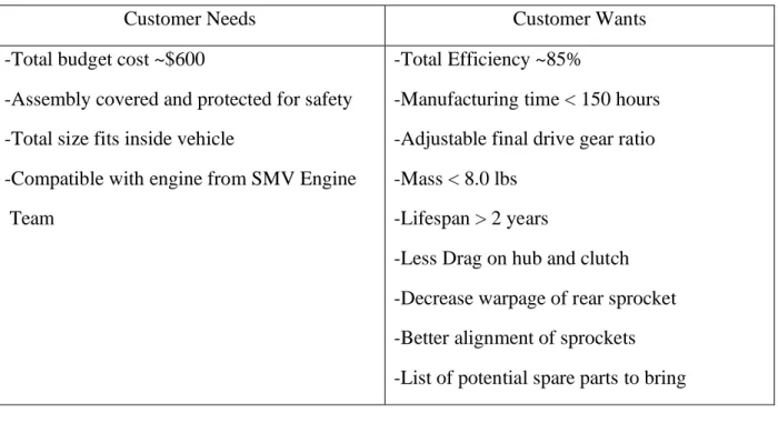
Based on meetings with the members of the SMV, input from Dr. Mello, and results of our research, a list of what the customer needs and a list of what the customer wants was created. These can be found in Table 1 below.
Table 1. List of Customer Needs and Wants for the Drivetrain
Customer Needs Customer Wants
-Total budget cost ~$600
-Assembly covered and protected for safety
-Total size fits inside vehicle
-Compatible with engine from SMV Engine
Team
-Total Efficiency ~85%
-Manufacturing time < 150 hours
-Adjustable final drive gear ratio
-Mass < 8.0 lbs
-Lifespan > 2 years
-Less Drag on hub and clutch
-Decrease warpage of rear sprocket
-Better alignment of sprockets
B . EX I S T I NG D E S I G N T A B L E
Below is a table consisting of existing designs from other universities and the previous Cal Poly SMV team, along with a photo and description.
Table 2. Existing Drivetrain Designs
Team Name Photo Description
Calvin College Team 16
Single gear reduction, chain and sprocket, reduction 12-18
Northern Arizona
Single gear reduction, composite v-belt, centrifugal clutch, aluminum drive sheave
University Laval Quebec
Single gear reduction, 125-150 teeth on the sprocket. Optimized sprocket design to reduce weight. Top speed 25mpg, 1.96 horsepower
Dalhousie University
2 step gear reduction, roller chain and sprockets,
planetary gearbox w/ 20:1 reduction, ceramic ball bearings, centrifugal clutch
Cal Poly SMV
C . P A T E N T S E A R C H T A B L E
Below is a table of patents, acquired from a patent search, that relate to our problem. The purpose of this research is to come up with ideas and methods that may aide us in designing, manufacturing, and assembling the drivetrain.
Table 3. List of Relevant Patents and Their Descriptions
Patent Title Patent
Number Description/Relativity
Self-Aligning Sprocket US3597988A
An adjustable sprocket with a spherical head that can align itself with the chain and other sprocket. May be useful in designing a method to assure the best alignment of the sprockets for high efficiency.
Water Jet
Sprocket Fabrication US5933955
A method developed for fabricating a drive sprocket for a US Army M113 TCV using a water jet that may more than double the life of the sprocket. May be useful for strengthening sprocket and increasing its life span.
Resin-based Friction Material for Low Drag
Hubs
US5478642
A friction material and the process of making it to be applied to a hub or clutch which can keep temperatures and friction effects low. Can be helpful in designing a more efficient hub.
High-Performance Sprag Clutch Assembly
US6902046
A high performance sprag clutch assembly for maximum torque applications. The assembly features reduced race eccentricity under load from interlocking stator caps. Could be useful for rear hub selection.
Multiple tension reducing sprockets in a chain and
sprocket system
US8430775
A system including multiple sprockets to avoid resonance frequencies in a high chain tension setup. The sequence of sprockets allow each individual sprocket to cancel the other sprocket’s resonance frequencies out. This is extremely useful for designing to avoid resonance frequencies.
D . T E CH N I C A L L I T E R A T U R E
a. Effects of Frictional Loss on Bicycle Chain Drive Efficiency [1]
i.Study frictional energy loss mechanisms associated with chain drive system. Chain tension and sprocket size had the largest effect on the efficiency of the drivetrain.
b. Planetary Helical Gear System [2]
i.Gearbox is very compact, power-weight ratio, and efficient. Gears have high contact ratio and operates relatively quietly. Carrier, planet, and sun gears. Sun acts as driven gear with planet at driver.
c. Purpose of Hub Assembly [3]
d. Fundamentals of Sprocket Design and Reverse Engineering of Rear Sprocket of a Yamaha CY80 Motorcycle [4]
i.Discusses dimensioning, drafting, chemical composition, material selection, choice of manufacturing process, heat treatment, surface finish and packaging as the steps that need to be followed for manufacturing a hardened sprocket.
E . SH E L L E C O / S M V R U L E S
Based on research done on the Shell-Eco Marathon Rules and the Super-Mileage Vehicle 2019 rules, a list of rules relating to the drivetrain was compiled. The most important ones are:
• The transmission and/or clutch must be designed to be able to disconnect the engine from the wheel so the vehicle can be stationary while the engine is running.
• Guards and shields must be used to cover any moving drivetrain components to protect damage to any fuel carrying components and to prevent any injuries to the driver.
• Vehicle must have a clutch. [5]
• For centrifugal/automatic clutches, the starter motor speed must always be below the engagement speed of the clutch. [5]
• For manual clutches, the starter motor must not be operable with the clutch engaged. An interlock is required to facilitate this functionality. [6]
F . CO N C E P T D ES I G N R ES E A R CH
Multiple concepts were considered for the design of the drivetrain. This section contains some research of the concepts we were considering but ultimately did not choose and the positives and negatives of each one.
Planetary Gearbox
A planetary gearbox is a gearbox in which there is one or more gears orbiting about the central axis of the train. The positives of a planetary gearbox are that it has high efficiency for heavy load and rpm purposes, and it will allow for a smaller rear sprocket thanks to a gear reduction [7]. The negatives are that it takes up space outside the motor shaft, which, from the dimensions given, we cannot do. Also, it would require moving the rear axle, which cannot be done. Finally, Planetary Gearbox are expensive, and cannot fit it in the budget.
Belt Driven
OBJECTIVES
The task for this project is to redesign the IC Drivetrain for the SMV team to maximize efficiency and performance for upcoming races in the Shell Eco Marathon and SMV competitions. The drivetrain includes all the components necessary to deliver power from the IC engine to the rear wheel. Specifically, this includes specifying a new clutch, transmission system, and rear hub with brake mounts.
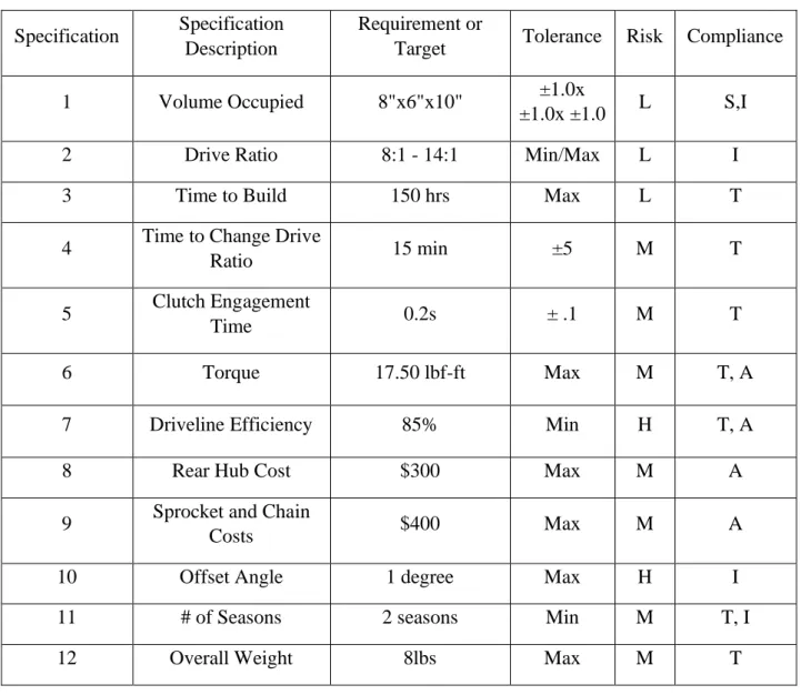
Table 4. Design Engineering Specifications
Specification Specification Description
Requirement or
Target Tolerance Risk Compliance
1 Volume Occupied 8"x6"x10" ±1.0x
±1.0x ±1.0 L S,I
2 Drive Ratio 8:1 - 14:1 Min/Max L I
3 Time to Build 150 hrs Max L T
4 Time to Change Drive
Ratio 15 min ±5 M T
5 Clutch Engagement
Time 0.2s ± .1 M T
6 Torque 17.50 lbf-ft Max M T, A
7 Driveline Efficiency 85% Min H T, A
8 Rear Hub Cost $300 Max M A
9 Sprocket and Chain
Costs $400 Max M A
10 Offset Angle 1 degree Max H I
11 # of Seasons 2 seasons Min M T, I
12 Overall Weight 8lbs Max M T
The methods that we will use to measure each specification are described below:
1. Volume Occupied: Can be initially measured using a yardstick, and if the completed drivetrain fits inside the vehicle in a similar manner to the existing drivetrain, we will have met our target.
2. Drive Ratio: This will be measured by counting the teeth in each sprocket.
3. Time to Build: By keeping a log of all the hours spent on building the vehicle, we can determine if we’ve met our target build time.
4. Time to Change Drive Ratio: This will be determined by timing several trials of changing the drive ratio with a stopwatch and averaging this number.
5. Clutch Engagement Time: We will also use a stopwatch and average the clutch engagement time for several trials.
7. Driveline Efficiency: By using a dynamometer we can measure the power output from the engine as well as the power that actually makes it to the wheels and transmits to the ground. Dividing the second power reading by the first will give us the driveline efficiency. 8. Rear Hub Cost: We will keep track of the rear hub cost by keeping a log of each
component and material purchased to manufacture the hub.
9. Sprocket and Chain Costs: This will also be determined by keeping a log.
10.Offset Angle: This will be calculated using trigonometry by placing a yardstick on the flat surfaces of both sprockets. They will be perfectly aligned if the yardstick rests on both faces evenly. If not, measurements will be taken between the sprockets to calculate the angle.
11.Number of Seasons: We will estimate the number of seasons the driveline will last before becoming ineffective or failing, through stress and fatigue analysis. This will be confirmed once the vehicle actually fails.
12.Overall Weight: The overall weight will be determined using a standard scale.
CONCEPT DESIGN
I D E A T I O N
After defining the project objectives and goals, the next step was to develop a concept to best satisfy each of the requirements listed above (see Objectives). Two major ideation sessions were conducted using the brainstorming and check list methods to produce numerous ideas to solve each of the individual requirements. Due to the nature of the project, each session focused on overall system design for the drivetrain as well as the subcomponents which included the clutch and rear hub. Documentation of the two sessions can be found in the appendix at the end of this report.
D R I V E T R A I N D ES I G N C O N C E PT M O D E L S
Following the brainstorming sessions, many of the ideas were then developed into concepts. The concepts are crude in this stage but were effective for to combining ideas created in the ideation sessions. A few of the top overall concepts are included below and were selected based on our team’s prediction on their ability to satisfy the specifications / metrics determined in the objectives.
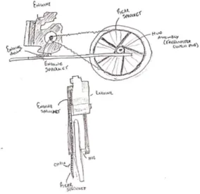
Concept 1: Single Stage Reduction – Chain + Sprocket
This concept resembles the drivetrain used in Cal Poly’s current SMV vehicle utilizing a chain and sprocket. The idea is that the engine power will be directly applied to a permanent driving sprocket at the engine shaft and deliver power with a chain to the driven sprocket. The driven sprocket will be designed to removable so that different final drive ratios can be varied depending on the conditions of the race. This will result in numerous sprockets being developed and will require high precision for chain alignment in order to prevent premature wear on the system.
Concept 2: Two Stage Reduction – Planetary Gearbox + Chain & Sprocket
This concept has resembled past SMV vehicle projects in which the final drive ratio is determined through two different reductions; one through a planetary gearbox, and then again reduced with a chain and sprocket. This design requires a less drastic change in sprocket size increasing chain efficiency. Purchasing gearbox would also be more reliable than a chain since there is less chance for misalignment. Space to fit the gearbox is a concern for this concept.
Figure 2. Two Stage Reduction – Planetary Gearbox + Chain & Sprocket
Concept 3: Single Stage Reduction – Gearbox
This concept eliminates the need for a chain in the drivetrain and instead relies on a gearbox to complete the required drive reduction. Changing final drive ratio could be a significant problem, requires designing a driveshaft, and difficult to space in the vehicle but can be very reliable, efficient, and should not have major issues with alignment.
Concept 4: Single Stage Reduction – Belt Drive
The belt drive is designed very similarly to concept 1 with the exception of replacing the chain & sprocket with a belt drive. A belt drive would be easy to change drive ratio, reduce noise and vibration of the vehicle, require no lubricant, economical, and do require parallel shafts. The biggest concern with using a belt drive is efficiency and reliability.
Figure 4. Single Stage Reduction – Belt Drive
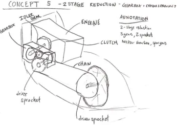
Concept 5: Two Stage Reduction – Gearbox + Chain Drive
This concept is similar to concept two except that the planetary gearbox is replaced with slimmer gearbox running down the length of the vehicle. This will make better use of the extra length of the vehicle vs the width. The gearbox will have a reduction around 3:1 to reduce the size of the sprockets. The driver gear will pass through an idler and transmit power to a shaft delivering power to the chain drive.
In addition to developing these overall concepts, subsystem concepts were also developed. Because all the overall systems can incorporate the subsystem concepts, they were not included in the sketches.
E V A L U A TI N G L E A D I NG C O N C EP T S
After developing several concepts for the overall and subsystems, Pugh matrices were developed to evaluate the strengths of these concepts against the requirements developed. In addition to the Pugh matrices, a morphological matrix was created to combine the strengths each concept and develop new concepts. Both the Pugh and morphological matrices can be found in Appendix C.
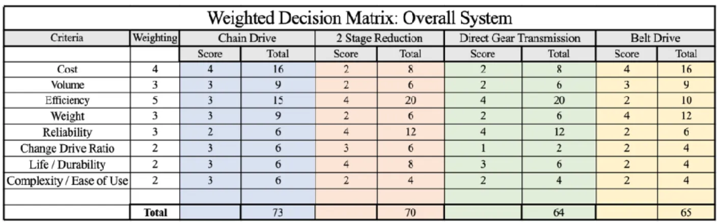
To determine the best final concept for the design, a weighted decision matrix and preliminary analysis was conducted to analyze the overall and subsystem concepts. Although many requirements of the design are difficult to measure in this stage of the design, preliminary analysis was used to roughly estimate certain metrics of the design. The analysis performed can be found in the appendix of this document. Efficiency, weight, precision, and space were roughly estimated for the 4 design concepts and helped influence the scores developed in the weighted decision matrix.
Efficiency for each of the drivetrain designs was estimated by using approximate max efficiencies for gears, belts, and chains and raising them to the power of the number of each component. Example: Efficiency (E) = .98 Number of Gears (N) = 4. Overall Efficiency = E^N = .98^4. Overall Efficiency = 0.922. If a drivetrain combines two different types of components, solve each efficiency separately and then multiply the component efficiencies together. Using this method, it was determined that all the concepts had the potential to satisfy our efficiency requirement, but the single stage chain drive concept had the highest potential efficiency at 92.2%.
After analyzing efficiency, estimated size of the concepts was analyzed. After contacting the SMV team, it was determined that our estimated space to place our drivetrain was approximately 8in (xdim), 6in (ydim), and 10in(zdim). These dimensions are based on the origin at the base of the engine shaft. It was determined that the only concept incapable of fitting within the chassis is the two-stage reduction with the planetary gearbox. Although initially this concept seemed to be a leading design, it does not seem possible to fit a clutch, gearbox, and sprocket from the engine shaft due to the tapering of the vehicle’s body.
The next criteria analyzed was the overall weight of the vehicle drivetrain. The goal of the project is to reduce the drivetrain weight by at least 20% from the current design. By reusing the same drivetrain plate, assuming similar weights for engine mounts, dropouts, chains etc., it was determined that it will be very difficult to reduce the weight of the drivetrain using these concepts. In the best-case scenario with the materials chosen, the maximum weight that can be reduced is about 10%. In order to reach the project goal, new materials will be evaluated, and various other options will be explored to save weight.
The last parameter our team analyzed was the overall cost to implement each drivetrain system. Using manufacturer retail prices, a cost table was constructed to estimate the building cost for each of the systems. After approximating each budget, it was determined that only single stage chain and belt drives were within our team’s budget. The cost analysis can be found in the appendix of the report.
After performing all the preliminary analysis, three decision matrices were constructed to reflect the information gathered in the analysis. The three decision matrices developed analyze overall system, clutch, and rear hub concepts. These can be found below.
Table 5. Overall System Weighted Decision Matrix
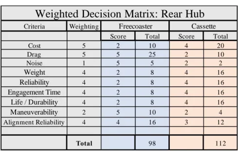
Table 7. Rear Hub Weighted Decision Matrix
R E A R H U B
At first, we planned to purchase a new rear hub based on extensive research about which hubs on the market would be an improvement over the previous Odyssey Freecoaster that was used. A decision matrix was constructed above in Table 7 comparing a typical cassette hub to a typical freecoaster hub, and it was ultimately determined that given a limited budget for purchasing a new hub, the standard cassette hub would be the most practical choice. While a freecoaster would essentially eliminate all rolling drag, its most desirable trait, due to their advanced technology they are much more expensive, heavier, less durable, and less reliable. Their incredibly delayed engagement time and their fragility is what we believe caused the SMV’s current hub to fail. This is because the torque being created from the motor is significantly higher than that of a cyclist’s pedal-which is what these hubs are designed to handle, and slow engagement allows the impact on the freecoaster’s pawls to be much greater than with the faster engagement seen in cassette hubs.
However, after learning about the cost of freecoasting hubs, we decided that instead of redesigning the entire drivetrain, we would just continue to use the existing clutch and concentrate on improving the sprocket and rear hub since their malfunction is what ultimately caused the vehicle to fail. Since we will now be mainly focusing on only two aspects of the drivetrain, we decided that it would be more cost-effective to manufacture our own hub, and it would allow us the freedom to design it to our needs.
Criteria Weighting
Score Total Score Total
Cost 5 2 10 4 20
Drag 5 5 25 2 10
Noise 1 5 5 2 2
Weight 4 2 8 4 16
Reliability 4 2 8 4 16
Engagement Time 4 2 8 4 16
Life / Durability 4 2 8 4 16
Maneuverability 2 5 10 2 4
Alignment Reliability 4 4 16 3 12
Total 98 112
Weighted Decision Matrix: Rear Hub
S E L E C T E D CO N C E P T
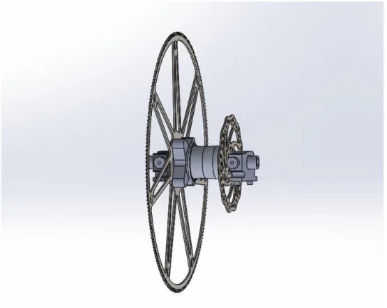
After finalizing the decision matrices, it was determined that a drivetrain that is single-stage chain-driven and uses a centrifugal clutch and cassette rear hub or custom hub will best satisfy the above requirements moving forward. Included below is the concept model including some of the most important features of the design.
Figure 6. Finalized CAD-generated drivetrain concept
the hub we manufacture were to fail, we would encourage the SMV team to purchase the Onyx hub pictured in figure 7 below.
Figure 7. Onyx BMX Ultra SSD ISO OX-110/15mm thru Rear Hub
R I SK S , CH A L L E N G ES , U N K NO WN S
FINAL D ESIGN
After careful analysis, the final proposed design is a single-stage reduction chain and sprocket drivetrain with a custom hub and water-jet steel sprocket. This proposed design highly resembles the current design but further emphasizes hub reliability and performance of the sprocket. The concept builds upon the design selected in the concept design phase with expanded dimensions, functionality, and safety considerations. The team made the decision to keep the single-stage reduction chain and sprocket drive because of the previously discussed advantages as well as no major safety concerns inhibiting the design. A figure of the final design can be seen below.
Figure 8. CAD of Final Design
Sprocket
the sprocket are placed in a circular bolt pattern and contains 4 M8x1.0 fasteners. A helicoil kit was purchased to prevent fastener stripping. The helicoils are installed in the sprocket mount which will be discussed in later sections. The sprocket contains 195 teeth with a ratio of 15:1 until the desired ratio is determined. While the vehicle is coasting, the sprocket will remain idle and have no loads applied. When the engine shaft begins running, the sprocket will engage approximately 5 teeth and produce a torque on the wheel. The teeth engagement was modeled in FEA based on the analysis of other team sprockets. In the first load case, a 17.5 lbf load is applied at each of the teeth. In the second load case, a 17.5 lbf load is applied to each of the 5 engaged teeth as well as a lateral load to simulate a 1 degree offset between the driver and driven sprocket. The results of the FEA can be seen below.
Figure 9a. Sprocket Design Figure 9b. Sprocket FEA
Figure 9. Custom Designed Sprocket
The location of the most stress is at the teeth where the loads are being applied. The factor of safety for the von mises stress & deflections was determined to be 1.8~2.0. Hand calculations for the sprocket were used to verify the FEA calculations are legitimate. These calculations can be found in Appendix J. To stay compliant with Shell Eco Marathon rules, the existing chain guard used by the team in the previous years will be reused to prevent significant injury to members of the team.
Hub Shell
The final hub design is modeled as a custom freecoaster hub using a sprag clutch bearing to simulate the coasting effect. The freecoaster hub shell is designed for a 36 spoke rim and contains a custom disk brake rotor mount. When the clutch engages, the shell will rotate
Figure 10. Custom Designed Hub with Brake Mount
Figure 11. Hub FEA
To ensure that the hub will not need replacement, loading calculations were performed by hand and analyzed using FEA to calculate the factors of safety for each load conditions. The most significant cases were loads due to impact, braking, and the torque while the clutch engages. The results of the FEA can be seen below, the hand calculations can be found in Appendix J.
Sprocket Mount
Figure 12. Custom Designed Sprocket Mount
extrusion is press fit into the sprag clutch bearing. When sprocket is rotating due to direct engine torque, it will cause the sprag clutch to engage causing the sprocket to drive the wheel. If the mount was directly attached to the hub shell, any rotation by the hub shell will cause the chain to drag resulting in reduced efficiency. Therefore, it was crucial that this mount remain separate from hub shell and rotate separately from the hub shell. On the sprocket side, a SMR2718-2R S/W7C SRI-2 radial bearing will be press fit into the cavity using a hydraulic press.
Figure 13. Sprocket Mount FEA
The most significant load case that the mount will likely endure is the engine torque case. The torque is applied at the bolt pattern with a fixed end where the sprag first engages at stall torque. Hand calculations and FEA were conducted to verify the design. The factor of safety was approximately 8.0 which is adequate for design. Hand calculations can be found in Appendix J.
Sprag Clutch Bearing
Figure 14. Boca Bearings CSK6005(X) One-way Sprag Clutch Bearing
internal parts engage allowing torque from drivetrain to apply to the hub/wheel. The dimensions and catalog rating of the bearing can be found in Appendix H. The sprag bearing engages very quickly and has a low friction value of 1.3 (N-cm), satisfying our engagement time requirement and reduced drag. In order to confirm that the bearing engages quickly, simple tests were conducted to measure the amount of rotation the bearing will undergo before engaging. From the simple tests, it was determined that the bearing engaged within 1-2 degrees. Further tests may be conducted to confirm the engagement strength and perhaps more accurate readings. The bearing torque rating will have a factor of safety of 4.5 which should account for any dynamic forces applied to the rear wheel. A torque wrench test was be conducted in the future to test the reliability of the bearing. Results of the torque-wrench test can be found in the testing section later in the report. In addition, a coast down test is conducted on the sprag bearing to estimate drag torque. This will be useful for measuring friction and efficiency. The results of the test can be seen in later sections of the report. Hand calculations can be found in Appendix J to confirm our results. The sprag clutch will be inserted into the hub cavity using a hydraulic press and will lock in using an interference fit.
Ball Bearing
Figure 15. Boca Bearings SMR2718-2R S/W7C SRI-2
Axle
Figure 16. Custom Designed Axle with Dropout Mounts
Figure 17. Axle FEA for Point Load
Existing System Components
MANUFACTU RING PLAN
Because of the complexity of the components for the drivetrain, proper planning must be done for the manufacturing of individual parts. This will help streamline the process and ensure no mistakes are made, which can save the money and time on the project. Material procurement and manufacturing for each part will be outlined in this section.
Sprocket
The current manufacturing plan for the sprocket begins with acquiring the material. Ideally, left over material from the club or another group should be utilized to undercut the project budget, but under the circumstance that free material isn’t available, it will be purchased through McMaster Carr. The primary material that is being considered is carbon steel because of its strength and durability. Carbon fiber was considered because of its superior strength over steel and while having a lower overall density, but the high cost and difficulty to manufacture has prevented the design from going in that direction. Once the material is acquired, a 1”x18”x18” steel fixture of the negative of the sprocket must be made to help machine the sprocket (assuming the team wants to machine the teeth). To cut the sprocket, a blank will be water-jetted and put into the fixture to machine the teeth. Once the sprocket is complete it can be mounted to the sprocket mount in the assembly using M8x1.0 bolts.
Hub
The hub will be made from a 3” block of aluminum 7075, which will be procured by a supplier if not through the club. It must be turned on a lathe and then run on a CNC mill. The part must be finished on a CNC Mill due to the contours for the rotor mount. Due to lack of experience on a lathe amongst group members, there is a chance that this operation will be outsourced. There is potential for the outsourcing to be free of at the least discounted, if the company is willing to help sponsor the project. Once the hub is complete and the bearings and axle are connected, the wheel can be attached by lacing the spokes through the drilled spoke holes. On the brake side of the hub, the disk brake will be attached to the hub using M5x0.8 bolts. On the sprocket side, the sprocket mount will sit in the inner race of the sprag bearing. This will allow for the hub to free coast, and the sprocket and sprocket mount will stay stationary relative to the hub.
Sprocket Mount
Axle
The manufacturing of the axle should be fairly simple. We will take a 20 mm diameter 1144 carbon steel rod and turn it down to 16mm for the axle itself to the length necessary to fit correctly between the dropout mounts (~125mm). Then, each end of the axle will be tapped and threaded to match the 14mm bolts on the dropout brackets. For the spacers, they will be turned on a lathe and the inside 16 mm hole will be drilled. The length and measurements of the spacers should be adjusted for best fit alignment for the system.
Bearings
There will be a total of 3 bearings used for the design of the hub. These bearings will be purchased through Boca Bearings. The primary bearing will be a sprag CSK6005X 25x47x14mm bearing. The brake-side bearing will be an F19-32-TP ball thrust bearing. These two bearings will be press fit into the hub shell using a hydraulic press. The final bearing will also be a ball bearing and will be connected to the sprocket mount to allow free coasting. No manufacturing will be required for bearings.
Drop Out Mounts
The same dropout mounts from the previous vehicle will be utilized. However, on the previous vehicle the brake side mount has a machined in spacer since the brake was mounted at a different location. However, because this design required the brake to be mounted to the hub, the dropout mount on that side must be machined to allow for more space. The driver side mount will not be altered.
DESIGN V ERIFICATION PLAN
Volume Occupied is the volume of space that the designed drivetrain takes up. To ensure that this specification was met, the team worked with other teams and members of the club to make sure the design fit within the required space. Additionally, many of the dimensions were modeled based on the previous design to also assure the volume occupied would not be more than the chassis would allow.
Drive Ratio is the ratio between the driving (front) sprocket and the rear sprocket. The club required a range from 8:1 to 15:1. The team designed one with a 15:1 ratio as a maximum with the ability to scale the design down to the needed ratio should the club want to manufacture more sprockets. Final size determined by simulation team.
Time to Build is how long it will take for all the drivetrain components to be manufactured. It has not come into play yet as the building process has not yet begun. Estimations were made for how long each component would take to manufacture.
needs to be unbolted from the mount and replaced with the new sprocket. Then everything is replaced where it needs to be. This process should not take more than 15 minutes. Clutch Engagement Angle is the degrees it takes for the clutch to engage when it is free coasting. Minimizing this would improve efficiency. To get this we will measure the degrees it takes for the clutch to engage.
Torque is the torque from the engine transmitted onto the sprocket. The given value was roughly 1.2 ft-lbs going through a 15:1 ratio, which results in a torque of 17.5 ft-lbs on the sprocket and hub. FEA was done to assure the components could handle the torque. Another method of testing could be to use a torque wrench and crank on the system and observe how high of a torque we can reach while simultaneously not damaging the system. Driveline Efficiency is how efficient the drivetrain is at transmitting the power from the engine to the wheel. This will be a percentage of the actual power transmitted vs the expected power transmitted. To test the efficiency, we will run the vehicle on a dynamometer.
Rear Hub Cost is the total cost to purchase the materials for and manufacture the hub. To minimize this the group has been reaching out to companies to see if any of them can spare material or sponsor some of the manufacturing.
Sprocket and Chain Costs is the total cost to purchase materials for and manufacture the sprocket and chain. Just like the hub, the group has been reaching out to companies and clubs to help reduce costs.
Offset Angle is the angle between the front and rear sprocket. If this angle is too great the chain can slip and cause problem. To ensure being able to line up the sprockets the drop out mounts allow for left and right adjustment of the system.,
Number of Seasons is the amount of years the drivetrain can last. For this we focused on the bearings and did a life calculation of them and found that they can last well over two years. These calculations can be found in Appendix J.
Overall Weight of the drivetrain is important as it plays into the fuel efficiency of the vehicle. The components were all designed with this in mind, cutting weight where possible without sacrificing integrity or strength of the components. Goal weights were determined using the previous vehicles numbers and the components were designed to be equal to or lighter than these components.
PROJECT MANAGEMEN T
R O L E S A N D R E S PO N SI BI L I TI E S
Team Roles:
Treasurer/Planner: Arya Mahdavian
- Maintain team’s travel & materials budgets (planning & tracking)
- Organize/maintain project plan/tracking
Secretary & Editor: Griffin Kraemer
- Organize/maintain information repository for team (online storage)
- Ensure documentation is complete, well-written, and timely
-Main point of communication with sponsor, coordinate sponsor meetings
Manufacturing/Testing: Kai Meter
- Coordinate build activities; arrange materials/equipment
- Conduct test activities; arrange facilities/instruments
- Compare theoretical data from analysis to experimental results
A P P R O A CH
Throughout the many different milestones and aspects of this project, the focus is making improvements to the components that will directly improve the efficiency, reliability, and driver usability of the drivetrain. After exploring the focuses of the previous drivetrain design group’s work, the team has noted several goals of the project. Our team decided that a single-stage reduction drivetrain had the most promise for achieving high efficiency, reliability, and driver usability. The advantage of the single-stage reduction is the reduction of parts, less contact friction, and easier maintenance. Components will be designed to mimic existing systems with improved functionality. The sprocket will be designed to reduce deflection as well as weight. The hub will have similar geometry but reduced weight and higher efficiency. Research will be done in material selection, manufacturing processes, and design for the fabricated mounting system. Emphasis will be placed on designing for manufacturing. Lastly, the system will be tested, and iterations will be made to improve on the design and locate issues for future improvements.
T I M E LI N E A N D D E L I V E R A B L ES
P L A N N E D A N A L Y S E S
As the team plans for the next stage of the project, component designs must be analyzed against the required specifications prior to manufacturing. The first component on the list is the manufactured hub assembly. It was determined that the sprag bearing could not take radial and axial loads. So, two precision ball bearings were be used on each side of the hub with a sprag bearing utilized within the hub. After this, FEA analysis was completed on the hub and mounts. Utilizing an analysis tool from ME 328 along with FEA, the team optimized dimensions and materials for the hub and mounts based on cost and safety factors. The next component that was designed was the rear sprocket. The previous senior project team utilized Fusion CAD to determine the best design for the sprocket; however, it has been shown to warp significantly under load. The new sprocket was designed by reverse engineering the winning team from Quebec’s sprocket from the previous year’s race.
Next, purchased components were tested against the team’s requirements to ensure the best components are selected for this application. The sprag bearing was tested for drag through the application of a torque-wrench and coast down test. Qualitatively, the team will determine an effective method of comparing multiple vendor’s sprag bearings based on drag. In addition to drag, the sprag bearings need to be tested for engagement time. This will be completed through the rotation slope prior to the sprags grabbing the axle. This will be measured in degrees of a rotation.
Lastly, the overall system design needs to be analyzed to ensure it meets the outline design requirements. Once the system has been designed and installed in the vehicle, testing on a dynamometer will be completed to ensure the overall efficiency goal was met. The horsepower and torque at the crankshaft will be determined and compared to the horsepower and torque at the rear wheel. The difference between these values will provide the overall system efficiency.
P L A N N E D P U R C H AS E S
Since our team plans on only focusing on designing and manufacturing a new rear sprocket and a new rear hub with brake and sprocket mounts, the planned purchases are exclusively for these components. The primary purchases for these parts include materials and a couple of off the shelf parts including bearings.
M A N U F A C T U R I NG A N D T E S TI NG P L A NS
With the design done and manufacturing starting, we will have to test the drag and engagement time of the sprag bearing we purchased from Boca Bearings. If the drag is considerably higher than what is optimal, measures will be taken to reduce it by removing seals and cleaning grease off the sprags.
The hub will be machined out of a 5” 7075-T6 aluminum bar. It will first be turned on a lathe, either a CNC lathe or a manual lathe. Once the bar is turned, fixturing will be developed to finish the turned part on a Haas CNC Mill. Currently, a pocket jaw set up appears to be the easiest process for finishing the hub on a CNC mill. After the hub has been machined, the hub will be surface ground to ensure proper flatness and parallelism on the mounting surfaces. The sprocket and sprocket mounts will be machined on a CNC Haas Mill. Lastly, the sprocket has the most time intensive manufacturing process as it is one of the most intricate components. A rough profile of the sprocket will be cut on a waterjet from a blanchard ground steel sheet. The waterjet blank sprocket will then be machined on a Haas CNC Mill if it is deemed necessary. If the waterjet does a sufficient job in cutting the sprocket, machining it will not be done to save on time. For the components that will be machined on a vertical Haas mill, tooling and fixturing needs to be designed.
The last step of testing prior to assembly will include a final inspection of all manufactured parts. Features will be measured against a detailed drawing of the solid model. Flatness and parallelism will also be inspected with an appropriate metrology device. If the team can gain access to a CMM, coordinate measuring machine, that will be the best method for ensuring accuracy of all features on the components. Once the individual parts are assembled, and bearings are press fit into the hub, testing of drag and efficiency can be done on individual parts. Then, once the entire assembly is complete it can be tested for overall efficiency on a dynamometer.
Cost Analysis
Maintenance Considerations
Many of the main considerations for maintaining the drivetrain can be found in Appendix O. In that section you can find instructions for the safe operation and maintenance of the drivetrain product. Specifically, it covers the adjustment / replacement of the drivetrain chain, replacing components within the dropouts, and replacing the sprocket. It is in the best interest of the
drivetrain life to regularly inspect and / or replace parts after each race. Critical components such as the sprocket, hub, and mounts should be inspected each race to look for signs of fatigue or failure. Fasteners should be replaced regularly so spares should be kept on the team at all times. To learn more, please flip to the Drivetrain Operation and Maintenance section in appendix O.
If any unexpected maintenance is needed, all of the parts could be replaced using the CAD parts and G code to run CNC operations. These models should be kept in the team’s CAD folder and archived if no longer used.
Safety Considerations
As with all projects, safety while operating on the vehicle is of the upmost importance. The primary potential hazard associated with the drivetrain design is the failure of important components during a race, potentially injuring the driver. One of the most critical components is the failure of the brake mount because of its impact on the functionality of the rear brake, but the risk of it failing is quite low due to a high factor of safety for that load case. There are many other risks that were analyzed prior to the manufacturing of the drivetrain components and can be found in Appendix K & L. The check list and FMEA showed that there were no potential hazards that would require additional hazard assessment. In addition, thorough testing on the primary components will reveal any additional hazards not accounted for during final design and manufacturing.
Product Realization & Manufacturing
Sprocket
Sprocket Mount
The material of the sprocket mount was 7075-T6 aluminum. The particular material for this component was 5” round bar stock. Utilizing a hydraulic programmable bandsaw, a 3” piece was cut from the stock material. This completed the stock preparation part of the manufacturing process.
For the machining portion of the manufacturing, the CAM programming was completed in Mastercam. This part required two operations on a standard 3-axis Haas Mill. The fixture solid was toolpathed, and then each operation was toolpathed. An aluminum pocket jaw fixture was chosen for both operations to allow easy workpiece holding. Due to the large diameter of the stock material, two 2.5”x5” jaws were squared up in a Kurt vice, and a light skim pass was made to ensure the jaws were square. Center of jaw was found using a touch probe. A 5” diameter cylindrical pocket was machined into the jaws. After this, the sprocket side of the sprocket mount was first machined on OP-1. 3/8” and ¼" end mills were used to mill the geometry of the part and interpolate the bearing counterbore and axle bore. After running the first operation of the part program, dimensions of the part were inspected prior to being pulled out of the vice. Once the part was determined to be true dimensionally, the part was pulled out of the vice. The jaws were flipped over, a light skim pass was made, and the touch probe was again utilized to set z-zero. For OP-2, the perimeter geometry of the sprocket mount was utilized to cut another pocket in the jaw. The part was loaded sprocket side down into the jaw. A 3/8” bullnose with .030” corner radius end mill was utilized to circle mill the boss. To machine the flange at the bottom of the boss with the proper corner radius, a 5/8” bullnose with .1875” corner radius end mill was utilized. The axle bore was then finished with a ¼" 4FL long flute end mill. After the second operation was complete, and the dimensions were checked against the detailed drawing, the part was pulled. A hand deburring tool was utilized to remove any burrs from the part. This completed the machining portion of the manufacturing.
Finally, hand finishing was needed to complete the part. To remove any residual burrs and machining marks, the part was placed into an aluminum vibratory finisher. This tumbling in stones greatly improved the surface finish of the part. The last step for this part was to install helicoils. Utilizing the M8x1.0 helicoil kit, an STI tap was run into the holes on the sprocket mount using a t-handle. Once the holes were tapped, the helicoil tool was utilized to install the helicoils into the tapped holes.
Hub
For the machining portion of the manufacturing, two different material removal methods were need due to the complex geometry of the part. First, the part was machined on a lathe. The bar was first faced to length. Then, the middle portion of the hub was turned to the final diameter. Finally, the spoke flanges and rotor mount flange were turned. The final part off the lathe consisted of four concentric cylinders. After this, the lathe part was machined in a similar manner as the sprocket mount. This part required two operations on a standard 3-axis Haas Mill post lathe operations. An aluminum pocket jaw fixture was again chosen for both operations to allow easy workpiece holding. Two 1”x5” jaws were squared up in a Kurt vice, and a light skim pass was made to ensure the jaws were square. Center of jaw was found using a touch probe. A 2.24” diameter cylindrical pocket was machined into the jaws. After this, the sprag side of the hub was first machined on OP-1. The spoke holes were center drilled, then drilled they were drilled with a .0938 carbide drill. The counterbore was interpolated with a ½" 3FL end mill. After running the first operation of the part program, dimensions of the part were inspected prior to being pulled out of the vice. Once the part was determined to be true dimensionally, the part was pulled out of the vice. The jaws were flipped over, a light skim pass was made, and the touch probe was again utilized to set z-zero. For OP-2, a 3” diameter cylindrical pocket was utilized to cut another pocket in the jaw. The part was loaded sprag side down into the jaw. The rotor mount was milled with a 3/8” 3FL end mill. The spoke holes were again center drilled and drilled with a .0938” drill. After the second operation was complete, and the dimensions were checked against the detailed drawing, the part was pulled. A hand deburring tool was utilized to remove any burrs from the part. This completed the machining portion of the manufacturing.
Finally, hand finishing was needed to complete the part. To remove any residual burrs and machining marks, the part was placed into an aluminum vibratory finisher. This tumbling in stones greatly improved the surface finish of the part. The last step for this part was to install helicoils. Utilizing the M6x0.8 helicoil kit, an STI tap was run into the holes on the sprocket mount using a t-handle. Once the holes were tapped, the helicoil tool was utilized to install the helicoils into the tapped holes.
Axle and Spacers
Assembly
After most of the components for the drivetrain were manufactured, the drivetrain was assembled. Unfortunately, not all of the components were completed by the end of this project but instructions on the installation of these parts have been included. Items such as the sprocket and spacers were not complete due to issues with the waterjet and the spacers need to be calibrated for alignment following the installation of the engine and rear brakes. Once the sprocket mount/ hub components are assembled, they were issued for testing. This subassembly is much easier to test the functionality of the system. Steps for assembling the entire drivetrain as well as testing have been included in the appendix of this report.
Design Verification & Testing
Torque Wrench Test
The first and most important test to be done is a torque test. The torque test will tell us if the sprag bearing inside the hub can stand to the max torque of the engine without slipping or failing. If it does fail, a stronger bearing or better method of fixturing the bearing to the hub must be found. To conduct the test, you must utilize a torque wrench, custom torque wrench fixture, and a vise. A full step by step breakdown of the test can be found in the user manual in Appendix Q. When conducting this test, our team noticed that the hub was slipping a bit out of the vise. To fix this, we clamped the hub by the brake mount within the vis. While testing we noticed that the structure of the hub was beginning to deform slightly but did not yield. When we completed this test, we found that the hub with the sprag bearing and sprocket mount was able to withstand a torque load of 35.5 ft-lb, which is the estimated max dynamic load assuming an engine torque output of 1hp. Therefore, we have confidence that the hub will work as it was designed.
Coast Down Testing Procedure
The second test to consider is a coast down test. This test can be used to measure the friction factor of the hub and sprocket mount assembly. By measuring how many rotations the assembly goes through as it slows from one RPM to second set RPM, you can see the effects of friction/drag that the assembly undergoes. To conduct this test you need a vise, a tachometer, and a camera with slow motion. The full step by step breakdown of the test can be found in the user manual in Appendix Q. Unfortunately, due to the COVID-19 outbreak shops and labs were closed making us unable to finish conducting this test. Using this test, the drag torque of this assembly can be found and compared to the manufacturing data and other hubs to directly compare drag at least until the dynamometer is completed.
Additional Testing
are completed, this test will help show if this prototype design is able to reach high enough efficiencies.
Specification Verification Checklist
Specification Specification Description
Requirement or Target
Test
Results Pass/Fail
1 Volume Occupied 8"x6"x10" 8”x6”x10” Pass
2 Drive Ratio 8:1 – 14:1 14:1 Pass
3 Time to Build 150 hrs 200 hrs Fail
4 Time to Change
Drive Ratio 15 min TBD TBD
5 Clutch
Engagement Time 0.2s TBD TBD
6 Torque 17.5 lbf-ft 35.2 lbf-ft Pass
7 Driveline
Efficiency 85% TBD TBD
8 Rear Hub Cost $300 $100 Pass
9 Sprocket and
Chain Costs $400 $0 Pass
10 Offset Angle 1 degree TBD TBD
11 # of Seasons 2 seasons TBD TBD
Because the entire assembly was not complete, the dynamometer was not finished, and the club vehicle was not assembled, many of the tests our team hoped to run could not be done. The system did fit within the vehicle so that specification was met. The sprocket was designed to be adjustable for different drive ratios and the hub/sprocket mount and sprag assembly was able to withstand twice the required torque load meaning those specifications were also met. The cost specifications were met as well because we were able to get material from the club. The only specification that failed at this time was the time to build. It took us over the expected 150 hours to build most of the parts. However, this is due to our minimal shop experience and other problems we ran into. The rest of the specifications can be checked once the entire assembly is completed. The weight of the components appears to be heavier than anticipated, meaning the overall weight would likely have been more than 8 lbs. Our team highly recommends optimizing the components for weight reduction in the future.
CONCLUSION
bearings and press fits due to slight errors during the manufacturing process. Recommendations to improve this process and the components themselves can be viewed in the section below. Testing results can also be found in the appendices. Overall, the drivetrain assembly is functioning, but additional improvements should be made prior to competition next spring.
Lessons Learned and Future Improvements
There are many improvements that can be made to improve the functionality and manufacturing process within the drivetrain components of the vehicle. In terms of functionality, the most significant improvements that can be made to manufactured components is reducing weight of the sprocket mount and hub. Both components were made to resist component failure but in turn excess material was left on the parts adding weight. Using the CAD models of the existing components, FEA should be conducted to locate areas were additional material can be cut away. During this process though, careful consideration should be made to ensure the improvements can actually be manufactured. In addition, the future design should investigate solutions that can allow the bearings to be easily removed in the event of bearing failure or replacement. The current method for removing bearings involves machining out the bearing and is not an ideal method for bearing removal. One of the bigger suggestions our team has for future teams is to buy more available components if within the team’s budget. Manufacturing custom components led to many issues down the road. Multiple bearings were replaced and errors due to manufacturing cost the team an additional 20% which prevented our team from coming way under budget.
In addition to improvements to the design, there are many suggestions or improvements that can be made to smoothen the manufacturing process. The first and most simple suggestion is to allot much more time for machining than anticipated. This will allow time for practicing toolpaths on practice/ scrap material. This will help identify issues with improvements and reduce headaches later in the manufacturing process. In terms of the bearings, shrink fit should be avoided. Using shrink fit on the sprag bearing melted the plastic retaining ring within the bearing and prevented the bearing from holding any torque. Therefore, press fits should be used on all the bearings. The press fit interference should be directly taken from the bearing supplier to prevent failure of the bearing or parts. The interference fits were calculated in the appendix but because parts were cut to be material safe, the interferences tended to run tight. Lastly, more research should be done to better fasten the components to the hub and sprocket. The helicoil kits purchase were very expensive and used about 20% of the overall budget. If a more cost-effective method is implemented, a lot of money can be saved securing the components together.
REFEREN CES
[1] Spicer, James B. “Effects of Frictional Loss on Bicycle Chain Drive Efficiency.” Journal of
Mechanical Design, American Society of Mechanical Engineers, 1 Dec. 2001,
mechanicaldesign.asmedigitalcollection.asme.org/article.aspx?articleid=1475974.
[2] Nitinkumar, Anekar, et al. “Planetary Helical Gear System.” Research Gate, MIT College of Engineering.
[3] Mahadik, S. S. (2018). Design and ANSYS analysis of Components of Wheel Assembly of
SAE Car. International Journal of Current Engineering and Technology,8(02). [4] Williams S, Ebhota. “Fundamentals of Sprocket Design and Reverse Engineering of Rear
Sprocket of a Yamaha CY80 Motorcycle.” Centre of Professional Research Publications, 2014. April 27, 2019.
[5] Shell. “Shell Eco-Marathon 2019 Official Rules Chapter 1.” Shell Eco-Marathon, 2019. April 14, 2019.
[6] SAE International. “2019 SAE Supermileage Rules.” SAE International, 2018. April 14, 2019.
[7] Anekar, Nitinkumar & Deshmukh, Suraj & Nimbalkar, Shrikant. (2014). Planetary Helical Gear System.
[8] Warner, Jack. “A Look at Belt, Chain and Gear Drive Technology.” A Look at Belt, Chain and Gear Drive Technology | Power Transmission Blog, 28 Nov. 2017,
APPENDICES
A P P E N D I X A: Q U A LI T Y F U N C TI O N D E P LO YM E N T
A P P E N D I X B: I D E A TI O N S E SS I O N S
A P P E N D I X C: P U G H A N D M O R PH O LO G I C A L M A T RI C E S
Table 8: Pugh Matrix-Overall System Design (Old Design)
Table 10: Pugh Matrix-Rear Hub Design (Existing)
Table 11: Morphological Matrix with Most Feasible designs
A P P E N D I X D: W E I G H T E D D E S I G N M A T R I C ES
Table 13: Weighted Design Matrix-Maximum Efficiency Analysis
Table 14: Weighted Design Matrix-Maximum Size Analysis
A P P E N D I X E: P R E L I M I N A R Y A NA L Y S I S
Figure 22. Preliminary Analysis-Precision Calcs
A P P E N D I X H : P RO D U C T L I T E RA T U R E
Bearings
One-way sprag bearing: CSK6005X
https://www.bocabearings.com/products/csk6005(x)-23082
Sprag Bearing Catalog
https://www.bocabearings.com/Files/Images/drawings/One-Way-Bearing-Catalog.pdf
Thrust Bearings: FP-19-32
https://www.bocabearings.com/products/smr2718-2rs-w7c-sri-2-14200
Sprocket
Steel Sheet: 18”x18”x¼”
https://www.mcmaster.com/1388k175
Sprocket Mount
5” Diam x ½’Aluminum Rod
https://www.midweststeelsupply.com/store/7075aluminumroundbar
Hub
https://www.mcmaster.com/standard-aluminum-rods/high-strength-7075-aluminum-rods-and-discs-7/
Axle
20mm Diam Rod by 1ft length
https://www.mcmaster.com/standard-steel-rods
Fasteners M8.0 Fasteners
https://www.homedepot.com/p/M8-1-0-x-25-mm-Class-8-8-Zinc-Plated-Hex-Bolt-813548/204273570 M5x0.8 Fasteners
https://www.homedepot.com/p/Everbilt-M5-0-8-x-40-mm-Class-8-8-Zinc-Plated-Hex-Bolt-801408/204273659
M14x1.5 Fasteners
https://www.homedepot.com/p/Everbilt-M14-2-0-x-40-mm-Class-8-8-Zinc-Plated-Hex-Bolt-802018/204779250
Helicoil Kits
https://www.oreillyauto.com/detail/b/heli-coil-3878/tools---equipment-16488/hand-tools-16814/cutting--- drilling-tools-16542/thread-repair-16906/heli-coil-inserts-19596/ec39e02ab378/heli-coil-m5-0-80-metric-thread-repair-kit/55465/4368747?q=HeliCoil+m5&pos=1
A P P E N D I X J : H A N D C A L C U L A TI O NS / A N A L Y SI S
Hub FEA: Engine Torque Load
Hub FEA: Braking Torque Load
Load Case Yield
Strength (N/m^2)Stress (N/m^2)Max of SafetyFactor
Engine Torque 5.05x10^8 2.421x10^78 2.09
Hub FEA: Impact Load
Load Case Yield
Strength (N/m^2)Stress (N/m^2)Max of SafetyFactor
Sprocket FEA: Engine Load with 1-degree offset
Sprocket FEA: Engine Load with 1-degree offset
Load Case Yield
Strength (N/m^2)Stress (N/m^2)Max of SafetyFactor
Engine Load +
Axle FEA: Point Load
Load Case Yield
Strength (psi) Stress (psi)Max of SafetyFactor
Impact Load
Load Case Yield
Strength (N/m^2)Stress (N/m^2)Max of SafetyFactor
Appendix N – Drivetrain Assembly
This user’s manual includes instructions for the assembly of this drivetrain product and important safety information. Read this section entirely including all safety warnings and cautions before assembling the product.
Important:
This product is meant for the Cal Poly Supermileage Vehicle Club gas powered vehicle. Before using this product, the user should be familiar with the operation and safety risks involved with the product.
Warning:
Do not assemble the drivetrain components without supervision from club advisor or other team members
Certain components of the design present safety hazards and therefore supervision is required in response to a potential emergency situation
The following instructions guide the safe assembly of the vehicle drivetrain.
Inserting bearings into custom hub
Follow these instructions to insert one-way sprag bearing and radial bearing into custom hub. 1. First, lie hub on to the table of hydraulic press with the smaller cavity faced down. The side with the brake mount should be faced down.
2. Place the sprag bearing flush with the large cavity which is approximately the same size. Make sure that the bearing rotates counterclockwise and locks when turned clockwise. This simulates the freecoaster function. It should now be ready for pressing
3. Using a hydraulic press, force the sprag bearing into cavity by applying even pressure across the bearing. Make sure pressure is not all applied on the inner race of the bearing or the bearing will fail.
4. After the sprag bearing has been inserted, flip the hub over so that side is face down. 5. Using the same press method, place the radial bearing in the brake mount cavity and press.
Lacing the custom hub to rear wheel
Follow these instructions to lace the custom hub to the rim of the rear wheel. 1. Follow the instructions on lacing the wheel using this website
a. https://www.sheldonbrown.com/wheelbuild.html
Inserting bearing into sprocket mount
Follow these instructions to insert radial bearing into sprocket mount.
1. After lacing the wheel and hub together, put this assembly aside and take out the sprocket mount.