350 East Plumeria Drive San Jose, CA 95134 USA
November, 2011
Web Management User Manual
Version 9.0.2 GSM5212P GSM7212F GSM7212P GSM7224P
©2011 NETGEAR, Inc. All rights reserved
No part of this publication may be reproduced, transmitted, transcribed, stored in a retrieval system, or translated into any language in any form or by any means without the written permission of NETGEAR, Inc.
Technical Support
Thank you for choosing NETGEAR. To register your product, get the latest product updates, get support online, or for more information about the topics covered in this manual, visit the Support website at
http://support.netgear.com .
Phone (US & Canada only): 1-888-NETGEAR
Phone (Other Countries): Check the list of phone numbers at
http://support.netgear.com/app/answers/detail/a_id/984
Trademarks
NETGEAR, the NETGEAR logo, ReadyNAS, ProSafe, ProSecure, Smart Wizard, Auto Uplink, X-RAID2, and NeoTV are trademarks or registered trademarks of NETGEAR, Inc. Microsoft, Windows, Windows NT, and Vista are registered trademarks of Microsoft Corporation. Other brand and product names are registered trademarks or trademarks of their respective holders.
Statement of Conditions
To improve internal design, operational function, and/or reliability, NETGEAR reserves the right to make changes to the products described in this document without notice. NETGEAR does not assume any liability that may occur due to the use, or application of, the product(s) or circuit layout(s) described herein.
Revision History
Publication Part Number Version Publish Date Comments
Chapter 1
Getting Started
Switch Management Interface . . . 8
Web Access. . . 8
Understanding the User Interfaces . . . 9
Using the Web Interface . . . 9
Using SNMP . . . 14
Interface Naming Convention . . . 14
Chapter 2
Configuring System Information
Management . . . 16System Information . . . 16
Switch Statistics. . . 21
System CPU Status . . . 24
Loopback Interface . . . 26
Network Interface. . . 27
Time. . . 31
DNS . . . 38
SDM Template Preference . . . 40
Services. . . 42
DHCP Server . . . 42
DHCP Relay . . . 51
DHCP L2 Relay . . . 52
UDP Relay . . . 55
PoE . . . 57
Basic . . . 57
Advanced. . . 59
SNMP . . . 64
SNMPV1/V2. . . 64
SNMP V3 . . . 70
LLDP . . . 71
LLDP . . . 72
LLDP-MED. . . 78
ISDP . . . 87
Basic . . . 87
Advanced. . . 88
Timer Schedule . . . 93
Timer Global Configuration . . . 93
Chapter 3
Configuring Switching Information
VLANs . . . .96
Basic . . . .97
Advanced . . . .99
Spanning Tree Protocol . . . .112
Basic . . . .112
Advanced . . . .115
Multicast . . . .127
MFDB . . . .127
IGMP Snooping . . . .129
MLD Snooping . . . .140
MVR Configuration . . . .147
Basic . . . .147
Advanced . . . .148
Address Table . . . .152
Basic . . . .152
Advanced . . . .154
Ports . . . .158
Port Configuration. . . .158
Port Description . . . .160
Link Aggregation Groups . . . .161
LAG Configuration . . . .162
LAG Membership . . . .163
Chapter 4
Routing
Routing Table . . . .166Basic . . . .167
Advanced . . . .169
IP . . . .171
Basic . . . .171
Advanced . . . .178
VLAN . . . .186
VLAN Routing Wizard. . . .187
VLAN Routing Configuration. . . .188
ARP . . . .189
Basic . . . .189
Advanced . . . .190
Router Discovery . . . .193
Chapter 5
Configuring Quality of Service
Class of Service . . . .197Basic . . . .197
Advanced . . . .199
Differentiated Services . . . .204
Auto VoIP Configuration . . . 207
Basic. . . 207
Advanced . . . 209
Chapter 6
Managing Device Security
Management Security Settings. . . 224Local User . . . 224
Enable Password Configuration . . . 227
Line Password Configuration . . . 227
RADIUS . . . 228
Configuring TACACS+ . . . 234
Authentication List Configuration . . . 236
Login Sessions . . . 240
Configuring Management Access. . . 241
HTTP . . . 241
HTTPS . . . 243
SSH . . . 246
Telnet . . . 249
Console Port. . . 251
Denial of Service . . . 252
Port Authentication . . . 253
Basic. . . 254
Advanced . . . 255
Traffic Control . . . 262
MAC Filter. . . 263
Port Security . . . 265
Private Group . . . 270
Protected Ports Configuration . . . 272
Storm Control . . . 273
Control . . . 275
DHCP Snooping . . . 275
IP Source Guard. . . 281
Dynamic ARP Inspection . . . 283
Configuring Access Control Lists . . . 288
ACL Wizard . . . 288
Basic. . . 289
Advanced . . . 294
Chapter 7
Monitoring the System
Ports . . . 308Port Statistics . . . 309
Port Detailed Statistics . . . 311
EAP Statistics . . . 317
Cable Test . . . 320
Command Log Configuration . . . .324
Console Log Configuration . . . .324
SysLog Configuration . . . .325
Trap Logs . . . .326
Event Logs . . . .328
Persistent Logs . . . .329
Port Mirroring . . . .330
Multiple Port Mirroring. . . .330
sFlow . . . .332
Basic . . . .332
Advanced . . . .333
Chapter 8
Maintenance
Save Configuration . . . .336Save Configuration . . . .336
Auto Install Configuration . . . .337
Reset . . . .337
Device Reboot . . . .338
Factory Default . . . .338
Password Reset . . . .339
Upload File From Switch. . . .339
File Upload . . . .340
HTTP File Upload . . . .341
USB File Upload . . . .342
Download File To Switch . . . .342
File Download . . . .343
HTTP File Download. . . .344
USB File Download. . . .346
File Management . . . .347
Copy . . . .347
Dual Image Configuration . . . .348
Troubleshooting . . . .349
Ping IPv4 . . . .349
Ping IPv6 . . . .350
Traceroute IPv4 . . . .351
Traceroute IPv6 . . . .352
Chapter 9
Help
Online Help. . . .354Support . . . .354
User Guide . . . .355
Appendix A
Default Settings
Virtual Local Area Networks (VLANs). . . 361
VLAN Example Configuration. . . 362
Access Control Lists (ACLs). . . 363
MAC ACL Example Configuration . . . 364
Standard IP ACL Example Configuration . . . 365
Differentiated Services (DiffServ) . . . 366
Class. . . 366
DiffServ Traffic Classes . . . 367
Creating Policies. . . 367
DiffServ Example Configuration . . . 368
802.1X . . . 370
802.1X Example Configuration. . . 371
MSTP . . . 372
MSTP Example Configuration . . . 374
Appendix C
Notification of Compliance
1
This chapter provides an overview of starting your NETGEAR ProSafe® Managed Switches and accessing the user interface. This chapter contains the following sections:• Switch Management Interface on page8
• Web Access on page8
• Understanding the User Interfaces on page9
• Interface Naming Convention on page14
Switch Management Interface
NETGEAR ProSafe® Managed Switches contain an embedded Web server and
management software for managing and monitoring switch functions. ProSafe® Managed Switches function as simple switches without the management software. However, you can use the management software to configure more advanced features that can improve switch efficiency and overall network performance.
Web-based management lets you monitor, configure, and control your switch remotely using a standard Web browser instead of using expensive and complicated SNMP software products. From your Web browser, you can monitor the performance of your switch and optimize its configuration for your network. You can configure all switch features, such as VLANs, QoS, and ACLs by using the Web-based management interface.
Web Access
To access the ProSafe® Managed Switches management interface:
• Open a Web browser and enter the IP address of the switch in the address field. You must be able to ping the IP address of the ProSafe® Managed Switches management interface from your administrative system for Web access to be available. If you did not change the IP address of the switch from the default value, enter 169.254.100.100 into the address field.
Understanding the User Interfaces
ProSafe® Managed Switches software includes a set of comprehensive management functions for configuring and monitoring the system by using one of the following methods:
• Web user interface
• Simple Network Management Protocol (SNMP) • Command Line Interface (CLI)
Each of the standards-based management methods allows you to configure and monitor the components of the ProSafe® Managed Switches software. The method you use to manage the system depends on your network size and requirements, and on your preference. The ProSafe® Managed Switch Web Management User Manual describes how to use the
Web-based interface to manage and monitor the system.
Using the Web Interface
To access the switch by using a Web browser, the browser must meet the following software requirements:
• HTML version 4.0, or later • HTTP version 1.1, or later
• Java Runtime Environment 1.6 or later
1. Open a Web browser and enter the IP address of the switch in the Web browser
address field.
2. The default username is admin, default password is none (no password). Type the
username into the field on the login screen and then click Login. Usernames and passwords are case sensitive.
3. After the system authenticates you, the System Information page displays.
The figure below shows the layout of the Managed Switch Web interface.
Page Menu
Configuration Status and Options Help Link
Help Page
LOGOUT Button Navigation Tab Feature Link
Navigation Tabs, Feature Links, and Page Menu
The navigation tabs along the top of the Web interface give you quick access to the various switch functions. The tabs are always available and remain constant, regardless of which feature you configure.
When you select a tab, the features for that tab appear as links directly under the tabs. The feature links in the blue bar change according to the navigation tab that is selected.
The configuration pages for each feature are available as links in the page menu on the left side of the page. Some items in the menu expand to reveal multiple configuration pages, as the following figure shows. When you click a menu item that includes multiple configuration pages, the item becomes preceded by a down arrow symbol and expands to display the additional pages.
Page Link
Configuration Pages
Configuration and Monitoring Options
The area directly under the feature links and to the right of the page menu displays the configuration information or status for the page you select. On pages that contain
configuration options, you can input information into fields or select options from drop-down menus.
Each page contains access to the HTML-based help that explains the fields and configuration options for the page. Each page also contains command buttons.
Table 1 shows the command buttons that are used throughout the pages in the Web
interface:
Table 1. Command Buttons
Button Function
ADD Clicking ADD adds the new item configured in the heading row of a table.
APPLY Clicking the APPLY button sends the updated configuration to the switch. Configuration
changes take effect immediately.
CANCEL Clicking CANCEL cancels the configuration on the screen and resets the data on the screen to the latest value of the switch.
DELETE Clicking DELETE removes the selected item.
REFRESH Clicking the REFRESH button refreshes the page with the latest information from the
Device View
The Device View is a Java® applet that displays the ports on the switch. This graphic provides an alternate way to navigate to configuration and monitoring options. The graphic also provides information about device ports, current configuration and status, table information, and feature components.
The Device View is available from the System Device View page.
The port coloring indicates whether a port is currently active. Green indicates that the port is enabled, red indicates that an error has occurred on the port, or red indicates that the link is disabled.
The Device View of the switch is shown below.
Click the port you want to view or configure to see a menu that displays statistics and configuration options. Click the menu option to access the page that contains the configuration or monitoring options.
If you click the graphic, but do not click a specific port, the main menu appears. This menu contains the same option as the navigation tabs at the top of the page.
Help Page Access
Every page contains a link to the online help , which contains information to assist in configuring and managing the switch. The online help pages are context sensitive. For example, if the IP Addressing page is open, the help topic for that page displays if you click Help.
User-Defined Fields
User-defined fields can contain 1 to 159 characters, unless otherwise noted on the configuration Web page. All characters may be used except for the following (unless specifically noted in for that feature):
\ <
/ >|
* |
?
Using SNMP
The ProSafe® Managed Switches software supports the configuration of SNMP groups and users that can manage traps that the SNMP agent generates.
ProSafe® Managed Switches use both standard public MIBs for standard functionality and private MIBs that support additional switch functionality. All private MIBs begin with a “-” prefix. The main object for interface configuration is in -SWITCHING-MIB, which is a private MIB. Some interface configurations also involve objects in the public MIB, IF-MIB.
SNMP is enabled by default. The System Management System Information Web page, which is the page that displays after a successful login, displays the information you need to configure an SNMP manager to access the switch.
Any user can connect to the switch using the SNMPv3 protocol, but for authentication and encryption, the switch supports only one user which is admin; therefore there is only one profile that can be created or modified.
To configure authentication and encryption settings for the SNMPv3 admin profile by using the Web interface:
1. Navigate to the System SNMP SNMPv3 User Configuration page.
2. To enable authentication, select an Authentication Protocol option, which is either MD5 or
SHA.
3. To enable encryption, select the DES option in the Encryption Protocol field. Then, enter
an encryption code of eight or more alphanumeric characters in the Encryption Key field.
4. Click APPLY.
To access configuration information for SNMPv1 or SNMPv2, click System SNMP SNMPv1/v2 and click the page that contains the information to configure.
Interface Naming Convention
The ProSafe® Managed Switches support physical and logical interfaces. Interfaces are identified by their type and the interface number. The physical ports are gigabit interfaces and
are numbered on the front panel. You configure the logical interfaces by using the software.
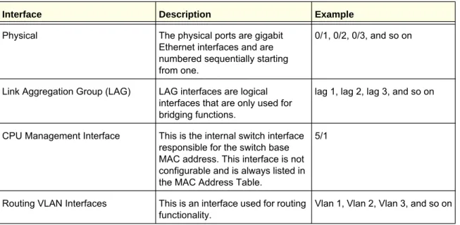
Table 2 describes the naming convention for all interfaces available on the switch.
Table 2. Naming Conventions for Interfaces
Interface Description Example
Physical The physical ports are gigabit Ethernet interfaces and are numbered sequentially starting from one.
0/1, 0/2, 0/3, and so on
Link Aggregation Group (LAG) LAG interfaces are logical interfaces that are only used for bridging functions.
lag 1, lag 2, lag 3, and so on
CPU Management Interface This is the internal switch interface responsible for the switch base MAC address. This interface is not configurable and is always listed in the MAC Address Table.
5/1
Routing VLAN Interfaces This is an interface used for routing functionality.
2
Use the features in the System tab to define the switch’s relationship to its environment. The System tab contains links to the following features:• Management on page16
• Device View (See Device View on page12)
• Services on page42
• PoE on page57
• SNMP on page64
• LLDP on page71
• ISDP on page87
• Timer Schedule on page93
Management
This section describes how to display the switch status and specify some basic switch information, such as the management interface IP address, system clock settings, and DNS information. From the Management link, you can access the following pages:
• System Information on page16
• Switch Statistics on page21
• System CPU Status on page24
• Loopback Interface on page26
• Network Interface on page27
• Time on page31
• DNS on page38
• SDM Template Preference on page40
System Information
After a successful login, the System Information page displays. Use this page to configure and view general device information.
To display the System Information page, click System Management System Information. A screen similar to the following displays.
The System Information provides various statuses:
Switch Status
To define system information:
1. Open the System Information page. 2. Define the following fields:
a. System Name - Enter the name you want to use to identify this switch. You may use up to 255 alphanumeric characters. The factory default is blank.
b. System Location - Enter the location of this switch. You may use up to 255 alphanumeric characters. The factory default is blank.
c. System Contact - Enter the contact person for this switch. You may use up to 25 alphanumeric characters. The factory default is blank.
d. Login Timeout - Specify how many minutes of inactivity should occur on a serial port connection before the switch closes the connection. Enter a number between 0 and 160: the factory default is 5. Entering 0 disables the timeout.
3. Click APPLY to send the updated screen to the switch and cause the changes to take effect
on the switch. These changes will not be retained across a power cycle unless a save is performed.
The following table describes the status information the System Page displays.
Field Description
Product Name The product name of this switch.
IPv4 Network Interface The IPv4 address and mask assigned to the network interface.
IPv6 Network Interface The IPv6 prefix and prefix length assigned to the network interface.
IPv4 Loopback Interface The IPv4 address and mask assigned to the loopback interface.
IPv6 Loopback Interface The IPv6 prefix and prefix length assigned to the loopback interface.
System Date The current date.
System Up time The time in days, hours and minutes since the last switch reboot.
System SNMP OID The base object ID for the switch's enterprise MIB. System Mac Address Universally assigned network address.
FAN Status
The screen shows the status of the fans in all units. These fans remove the heat generated by the power, CPU and other chipsets, make chipsets work normally. Fan status has three possible values: OK, Failure, Not Applicable (NA).
The following table describes the Fan Status information.
Field Description
UNIT ID The unit identifier is assigned to the switch which the fan belongs to.
FAN The working status of the fan in each unit.
Click REFRESH to refresh the system information of the switch.
Temperature Status
The screen shows the current temperature of the CPU and MACs. The temperature is instant and can be refreshed when the REFRESH button is pressed. The maximum temperature of CPU and MACs depends on the actual hardware.
The following table describes the Temperature Status information.
Field Description
CPU The current temperature of the CPU in the switch.
MAC The current temperature of the MACs in the switch.
Click REFRESH to refresh the system information of the switch.
Device Status
The screen shows the software version of each device. The following table describes the Device Status information.
Field Description
Firmware Version The release.version.maintenance.build number of the code currently running on the switch. For example, if the release was 8, the version was 0, the maintenance number was 3, and the build number was 11, the format would be ‘8.0.3.11’.
Boot Version The version of the boot code which is in the flash memory to load the firmware into the memory.
Click REFRESH to refresh the system information of the switch.
Serial Number The serial number of this switch.
RPS Indicates the status of the RPS. The status has three
possible values:
• Not Present: RPS bank not connected • OK: RPS bank connected.
• FAIL: RPS is present, but power is failed. Power Module Indicates the status of the internal power module.
PoE Version Version of the PoE controller FW image.
MAX PoE Indicates the status of maximum PoE power
available on the switch as follows:
• ON: Indicates less than 7W of PoE power available for another device.
• OFF: Indicates at least 7W of PoE power available for another device.
• N/A: Indicates that PoE is not supported by the unit.
Switch Statistics
Use this page to display the switch statistics.
To display the Switch Statistics page, click System > Management > Switch Statistics. A screen similar to the following displays.
The following table describes Switch Statistics information.
Field Description
ifIndex This object indicates the ifIndex of the interface table entry associated with the Processor of this switch. Octets Received The total number of octets of data received by the
processor (excluding framing bits but including FCS octets).
Packets Received Without Errors The total number of packets (including broadcast packets and multicast packets) received by the processor.
Unicast Packets Received The number of subnetwork-unicast packets delivered to a higher-layer protocol.
Multicast Packets Received The total number of packets received that were directed to a multicast address. Note that this number does not include packets directed to the broadcast address.
Broadcast Packets Received The total number of packets received that were directed to the broadcast address. Note that this does not include multicast packets.
Receive Packets Discarded The number of inbound packets which were chosen to be discarded even though no errors had been detected to prevent their being deliverable to a higher-layer protocol. A possible reason for
discarding a packet could be to free up buffer space. Octets Transmitted The total number of octets transmitted out of the
interface, including framing characters.
Packets Transmitted Without Errors The total number of packets transmitted out of the interface.
Unicast Packets Transmitted The total number of packets that higher-level protocols requested be transmitted to a
subnetwork-unicast address, including those that were discarded or not sent.
Multicast Packets Transmitted The total number of packets that higher-level protocols requested be transmitted to a Multicast address, including those that were discarded or not sent.
Broadcast Packets Transmitted The total number of packets that higher-level protocols requested be transmitted to the Broadcast address, including those that were discarded or not sent.
Transmit Packets Discarded The number of outbound packets which were chosen to be discarded even though no errors had been detected to prevent their being deliverable to a higher-layer protocol. A possible reason for
discarding a packet could be to free up buffer space. Most Address Entries Ever Used The highest number of Forwarding Database
Address Table entries that have been learned by this switch since the most recent reboot.
Address Entries in Use The number of Learned and static entries in the Forwarding Database Address Table for this switch.
Click CLEAR to clear all the counters, resetting all switch summary and detailed statistics to default values. The discarded packets count cannot be cleared.
Maximum VLAN Entries The maximum number of Virtual LANs (VLANs) allowed on this switch.
Most VLAN Entries Ever Used The largest number of VLANs that have been active on this switch since the last reboot.
Static VLAN Entries The number of presently active VLAN entries on this switch that have been created statically.
Dynamic VLAN Entries The number of presently active VLAN entries on this switch that have been created by GVRP registration. VLAN Deletes The number of VLANs on this switch that have been
created and then deleted since the last reboot. Time Since Counters Last Cleared The elapsed time, in days, hours, minutes, and
seconds, since the statistics for this switch were last cleared.
System CPU Status
Use this page to display the system resources.
To display the System Resource page, click System > Management > System CPU Status. A screen similar to the following displays.
System CPU Status
The following table describes CPU Memory Status information.
Field Description
Total System Memory The total memory of the switch in KBytes. Available Memory The available memory space for the switch in
CPU Utilization Information
This page displays the CPU Utilization information, which contains the memory information, task-related information and percentage of CPU utilization per task.
Loopback Interface
Use this page to create, configure, and remove Loopback interfaces.
To display the Loopback Interface page, click System > Management > Loopback Interface. A screen similar to the following displays.
1. Use the Loopback Interface Type field to select IPv4 or IPv6 loopback interface to
configure the corresponding attributes.
2. Use the Loopback ID field to select list of currently configured loopback interfaces.
3. Use the Primary Address field to input the primary IPv4 address for this interface in dotted
decimal notation. This option only visible when IPv4 loopback is selected.
4. Use the Primary Mask field to input the primary IPv4 subnet mask for this interface in dotted
decimal notation. This option only visible when IPv4 loopback is selected.
5. Use the Secondary IP Address field to input the secondary IP address for this interface in
dotted decimal notation. This input field is visible only when 'Add Secondary' is selected. This option only visible when IPv4 loopback is selected.
6. Use the Secondary Subnet Mask field to input the secondary subnet mask for this interface
in dotted decimal notation. This input field is visible only when 'Add Secondary' is selected. This option only visible when IPv4 loopback is selected.
7. Use the IPv6 Mode field to enable IPv6 on this interface using the IPv6 address. This option
is only configurable prior to specifying an explicit IPv6 address. This option only visible when IPv6 loopback is selected.
8. Use the IPv6 Address field to enter the IPv6 address in the format prefix/length. This option
only visible when IPv6 loopback is selected.
9. Use the EUI64 field to optionally specify the 64-bit extended unique identifier (EUI-64). This
Network Interface
From the Network Interface link, you can access the following pages:
• IPv4 Network Configuration on page27
• IPv6 Network Interface Configuration on page29
• IPv6 Network Interface Neighbor Table on page30
IPv4 Network Configuration
To display the IPv4 Network Configuration page, click System > Management > Network Interface > IPv4 Network Configuration. A screen similar to the following displays.
The network interface is the logical interface used for in-band connectivity with the switch via any of the switch's front panel ports. The configuration parameters associated with the switch's network interface do not affect the configuration of the front panel ports through which traffic is switched or routed
To access the switch over a network you must first configure it with IP information (IP address, subnet mask, and default gateway). You can configure the IP information using any of the following:
• BOOTP • DHCP
Once you have established in-band connectivity, you can change the IP information using any of the following:
• Terminal interface via the EIA-232 port • Terminal interface via telnet
• SNMP-based management • Web-based management
1. Use IP Address to specify the IP address of the interface. The factory default value is
169.254.100.100.
2. Use Subnet Mask to enter the IP subnet mask for the interface. The factory default value is
255.255.0.0.
3. Use Default Gateway to specify the default gateway for the IP interface. The factory default
value is 0.0.0.0
4. Use Locally Administered MAC Address to configure a locally administered MAC address
for in-band connectivity instead of using the burned-in universally administered MAC address. In addition to entering an address in this field, you must also set the MAC address type to locally administered. Enter the address as twelve hexadecimal digits (6 bytes) with a colon between each byte. Bit 1 of byte 0 must be set to a 1 and bit 0 to a 0, in other words, byte 0 must have a value between x'40' and x'7F'.
5. Use MAC Address type to specify whether the burned-in or the locally administered MAC
address should be used for in-band connectivity. The factory default is to use the burned-in MAC address
6. Use Current Network Configuration Protocol to specify what the switch should do
following power-up: transmit a Bootp request, transmit a DHCP request, or do nothing (none). The factory default is DHCP.
7. Use DHCP Vendor Class Identifier to enable DHCP VendorId option on the client.
8. Use DHCP Vendor Class Identifier String to specify DHCP VendorId option string on the
client.
9. Use Management VLAN ID to specify the management VLAN ID of the switch. It may be
configured to any value in the range of 1 - 4093. The management VLAN is used for management of the switch. This field is configurable for administrative users and read-only for other users.
The following table describes IPv4 Network Configuration information.
Field Description
Burned In MAC Address The burned-in MAC address used for in-band
connectivity if you choose not to configure a locally administered address.
IPv6 Network Interface Configuration
To display the IPv6 Network Configuration page, click System > Management > Network Interface > IPv6 Network Interface Configuration. A screen similar to the following displays.
The IPv6 network interface is the logical interface used for in-band connectivity with the switch via any of the switch's front panel ports. The configuration parameters associated with the switch's network interface do not affect the configuration of the front panel ports through which traffic is switched or routed.
To access the switch over an IPv6 network you must first configure it with IPv6 information (IPv6 prefix, prefix length, and default gateway). You can configure the IP information using any of the following:
• IPv6 Auto Configuration • DHCPv6
• Terminal interface via the EIA-232 port
Once you have established in-band connectivity, you can change the IPv6 information using any of the following:
• Terminal interface via the EIA-232 port • Terminal interface via telnet
• SNMP-based management • Web-based management
1. Use Admin Mode to enable or disable the IPv6 network interface on the switch. The
default value is enable.
2. Use IPv6 Address Auto Configuration Mode to set the IPv6 address for the IPv6 network
interface in auto configuration mode if this option is enabled. The default value is disable. Auto configuration can be enabled only when IPv6 Auto config or DHCPv6 are not enabled
3. Use Current Network Configuration Protocol to configure the IPv6 address for the IPv6
network interface by DHCPv6 protocol if this option is enabled. The default value is None. DHCPv6 can be enabled only when IPv6 Auto config or DHCPv6 are not enabled on any of the management interfaces.
4. Use DHCPv6 Client DUID to specify an Identifier used to identify the client's unique DUID
value. This option only displays when DHCPv6 is enabled.
5. Use IPv6 Gateway to specify the gateway for the IPv6 network interface. The gateway
address is in IPv6 global or link-local address format.
6. Use IPv6 Prefix/Prefix Length to add the IPv6 prefix and prefix length to the IPv6 network
interface. The address is in global address format.
7. Use EUI64 to specify whether to format the IPv6 address in EUI-64 format. Default value is
false.
8. Click ADD to add a new IPv6 address in global format. 9. Click DELETE to delete a selected IPv6 address.
IPv6 Network Interface Neighbor Table
Use this page to display IPv6 Network Port Neighbor entries.
To display the IPv6 Network Neighbor page, click System > Management > Network Interface > IPv6 Network Interface Neighbor Table. A screen similar to the following displays.
The following table displays IPv6 Network Interface Neighbor Table information.
Field Description
IPv6 address The Ipv6 Address of a neighbor switch visible to the network interface.
MAC address The MAC address of a neighbor switch.
IsRtr True(1) if the neighbor machine is a router, false(2)
Time
ProSafe® Managed Switches software supports the Simple Network Time Protocol (SNTP). You can also set the system time manually
SNTP assures accurate network device clock time synchronization up to the millisecond. Time synchronization is performed by a network SNTP server. ProSafe® Managed Switches software operates only as an SNTP client and cannot provide time services to other systems. Time sources are established by Stratums. Stratums define the accuracy of the reference clock. The higher the stratum (where zero is the highest), the more accurate the clock. The device receives time from stratum 1 and above since it is itself a stratum 2 device.
The following is an example of stratums:
• Stratum 0: A real-time clock is used as the time source, for example, a GPS system. • Stratum 1: A server that is directly linked to a Stratum 0 time source is used. Stratum 1
time servers provide primary network time standards.
• Stratum 2: The time source is distanced from the Stratum 1 server over a network path. For example, a Stratum 2 server receives the time over a network link, via NTP, from a Stratum 1 server.
Information received from SNTP servers is evaluated based on the time level and server type.
SNTP time definitions are assessed and determined by the following time levels: • T1: Time at which the original request was sent by the client.
• T2: Time at which the original request was received by the server. • T3: Time at which the server sent a reply.
• T4: Time at which the client received the server's reply. The device can poll Unicast server types for the server time.
Neighbor State The state of the neighboring switch:
• reachable(1) - The neighbor is reachable by this switch.
• stale(2) - Information about the neighbor is scheduled for deletion.
• delay(3) - No information has been received from neighbor during delay period.
• probe(4) - Switch is attempting to probe for this neighbor.
• unknown(6) - Unknown status.
Last Updated The last sysUpTime that this neighbor has been updated.
Polling for Unicast information is used for polling a server for which the IP address is known. SNTP servers that have been configured on the device are the only ones that are polled for synchronization information. T1 through T4 are used to determine server time. This is the preferred method for synchronizing device time because it is the most secure method. If this method is selected, SNTP information is accepted only from SNTP servers defined on the device using the SNTP Server Configuration page.
The device retrieves synchronization information, either by actively requesting information or at every poll interval.
SNTP Global Configuration
Use the SNTP Global Configuration pageto view and adjust date and time settings.
To display the SNTP Global Configuration page, click System Management > Time SNTP Global Configuration.
SNTP Global Configuration
SNTP stands for Simple Network Time Protocol. As its name suggests, it is a less
complicated version of Network Time Protocol, which is a system for synchronizing the clocks of networked computer systems, primarily when data transfer is handled via the Internet.
1. Use Client Mode to specify the mode of operation of SNTP Client. An SNTP client may
operate in one of the following modes.
• Disable - SNTP is not operational. No SNTP requests are sent from the client nor are
any received SNTP messages processed.
• Unicast - SNTP operates in a point to point fashion. A unicast client sends a request
to a designated server at its unicast address and expects a reply from which it can determine the time and, optionally the round-trip delay and local clock offset relative to the server.
• Broadcast - SNTP operates in the same manner as multicast mode but uses a local broadcast address instead of a multicast address. The broadcast address has a single subnet scope while a multicast address has Internet wide scope.
Default value is Disable.
2. Use Port to specify the local UDP port to listen for responses/broadcasts. Allowed range is 1 to 65535. Default value is 123.
3. Use Unicast Poll Interval to specify the number of seconds between unicast poll requests expressed as a power of two when configured in unicast mode. Allowed range is (6 to 10). Default value is 6.
4. Use Broadcast Poll Interval to specify the number of seconds between broadcast poll requests expressed as a power of two when configured in broadcast mode. Broadcasts received prior to the expiry of this interval are discarded. Allowed range is (6 to 10). Default value is 6.
5. Use Unicast Poll Timeout to specify the number of seconds to wait for an SNTP response when configured in unicast mode. Allowed range is (1 to 30). Default value is 5.
6. Use Unicast Poll Retry to specify the number of times to retry a request to an SNTP server after the first time-out before attempting to use the next configured server when configured in unicast mode. Allowed range is (0 to 10). Default value is 1.
7. When using SNTP/NTP time servers to update the switch's clock, the time data received from the server is based on Coordinated Universal Time (UTC) which is the same as Greenwich Mean Time (GMT). This may not be the time zone in which the switch is located. Use Time Zone Name to configure a timezone specifying the number of hours and
optionally the number of minutes difference from UTC with Offset Hours and Offset Minutes. The time zone can affect the display of the current system time. The default value is UTC. 8. Use Offset Hours to specify the number of hours difference from UTC. See Time Zone Name
(step7 previous) for more information. Allowed range is (-24 to 24).The default value is 0.
9. Use Offset Minutes to specify the number of Minutes difference from UTC. See Time Zone Name (step7 previous) for more information. Allowed range is 0 to 59. The default value is 0.
SNTP Global Status
The following table displays SNTP Global Status information.
Field Description
Version Specifies the SNTP Version the client supports.
Supported Mode Specifies the SNTP modes the client supports. Multiple modes may be supported by a client. Last Update Time Specifies the local date and time (UTC) the SNTP
client last updated the system clock.
Last Attempt Time Specifies the local date and time (UTC) of the last SNTP request or receipt of an unsolicited message.
SNTP Server Configuration
Use the SNTP Server Configuration page to view and modify information for adding and
Last Attempt Status Specifies the status of the last SNTP request or unsolicited message for both unicast and broadcast modes. If no message has been received from a server, a status of Other is displayed. These values are appropriate for all operational modes.
• Other - None of the following enumeration values. • Success - The SNTP operation was successful and
the system time was updated.
• Request Timed Out - A directed SNTP request timed out without receiving a response from the SNTP server.
• Bad Date Encoded - The time provided by the SNTP server is not valid.
• Version Not Supported - The SNTP version supported by the server is not compatible with the version supported by the client.
• Server Unsynchronized - The SNTP server is not synchronized with its peers. This is indicated via the 'leap indicator' field on the SNTP message. • Server Kiss Of Death - The SNTP server indicated
that no further queries were to be sent to this server. This is indicated by a stratum field equal to 0 in a message received from a server.
Server IP Address Specifies the IP address of the server for the last received valid packet. If no message has been received from any server, an empty string is shown.
Address Type Specifies the address type of the SNTP Server
address for the last received valid packet.
Server Stratum Specifies the claimed stratum of the server for the last received valid packet.
Reference Clock Id Specifies the reference clock identifier of the server for the last received valid packet.
Server Mode Specifies the mode of the server for the last received valid packet.
Unicast Server Max Entries Specifies the maximum number of unicast server entries that can be configured on this client.
Unicast Server Current Entries Specifies the number of current valid unicast server entries configured for this client.
Broadcast Count Specifies the number of unsolicited broadcast SNTP messages that have been received and processed by the SNTP client since last reboot.
To display the SNTP Server Configuration page, click System Management Time SNTP Server Configuration.
To configure a new SNTP Server:
1. Enter the appropriate SNTP server information in the available fields:
• Server Type - Specifies whether the address for the SNTP server is an IP address
(IPv4) or hostname (DNS). Default value is IPv4.
• Address - Specify the address of the SNTP server. This is a text string of up to 64
characters containing the encoded unicast IP address or hostname of a SNTP server. Unicast SNTP requests will be sent to this address. If this address is a DNS
hostname, then that hostname should be resolved into an IP address each time a SNTP request is sent to it.
• Port - Enter a port number on the SNTP server to which SNTP requests are sent. The
valid range is 1–65535. The default is 123.
• Priority - Specify the priority of this server entry in determining the sequence of
servers to which SNTP requests will be sent. The client continues sending requests to different servers until a successful response is received or all servers are exhausted. This object indicates the order in which to query the servers. A server entry with a precedence of 1 will be queried before a server with a priority of 2, and so forth. If more than one server has the same priority then the requesting order will follow the lexicographical ordering of the entries in this table. Allowed range is (1 to 3). Default value is 1.
• Version - Enter the NTP version running on the server. The range is 1–4. The default
is 4.
2. Click ADD.
3. Repeat the previous steps to add additional SNTP servers. You can configure up to three
SNTP servers.
4. To removing an SNTP server, select the check box next to the configured server to remove,
5. To change the settings for an existing SNTP server, select the check box next to the
configured server and enter new values in the available fields, and then click APPLY. Configuration changes take effect immediately.
6. Click CANCEL to cancel the configuration on the screen and reset the data on the screen to
the latest value of the switch.
7. Click REFRESH to refresh the page with the most current data from the switch.
SNTP Server Status
The SNTP Server Status table displays status information about the SNTP servers configured on your switch. The following table describes the SNTP Global Status fields. The following table displays SNTP Server Status information.
Field Description
Address Specifies all the existing Server Addresses. If no Server configuration exists, a message saying “No SNTP server exists” flashes on the screen.
Last Update Time Specifies the local date and time (UTC) that the response from this server was used to update the system clock. Last Attempt Time Specifies the local date and time (UTC) that this SNTP
server was last queried.
Last Attempt Status Specifies the status of the last SNTP request to this server. If no packet has been received from this server, a status of Other is displayed.
• Other - None of the following enumeration values. • Success - The SNTP operation was successful and the
system time was updated.
• Request Timed Out - A directed SNTP request timed out without receiving a response from the SNTP server. • Bad Date Encoded - The time provided by the SNTP
server is not valid.
• Version Not Supported - The SNTP version supported by the server is not compatible with the version supported by the client.
• Server Unsynchronized - The SNTP server is not synchronized with its peers. This is indicated via the 'leap indicator' field on the SNTP message.
• Server Kiss Of Death - The SNTP server indicated that no further queries were to be sent to this server. This is indicated by a stratum field equal to 0 in a message received from a server.
Requests Specifies the number of SNTP requests made to this server since last agent reboot.
Failed Requests Specifies the number of failed SNTP requests made to this server since last reboot.
DNS
You can use these pages to configure information about DNS servers the network uses and how the switch operates as a DNS client.
DNS Configuration
Use this page to configure global DNS settings and DNS server information. To access this page, click System Management DNS DNS Configuration.
To configure the global DNS settings:
1. Specify whether to enable or disable the administrative status of the DNS Client. • Enable - Allow the switch to send DNS queries to a DNS server to resolve a DNS
domain name. Default value is Enable.
• Disable - Prevent the switch from sending DNS queries.
2. Enter the DNS default domain name to include in DNS queries. When the system is
performing a lookup on an unqualified hostname, this field is provided as the domain name (for example, if default domain name is netgear.com and the user enters test, then test is changed to test.netgear.com to resolve the name). The length of the name should not be longer than 255 characters.
3. Use Retry Number to specify the number of times to retry sending DNS queries to DNS
server. This number ranges from 0 to 100. The default value is 2.
4. Use Response Timeout (secs) to specify the amount of time, in seconds, to wait for a
response to a DNS query. This timeout ranges from 0 to 3600. The default value is 3.
5. To specify the DNS server to which the switch sends DNS queries, enter an IP address in
standard IPv4 dot notation in the DNS Server Address and click ADD. The server appears in the list below. You can specify up to eight DNS servers. The precedence is set in the order created.
6. To remove a DNS server from the list, select the check box next to the server you want to
remove and click DELETE. If no DNS server is specified, the check box is global and will delete all the DNS servers listed.
7. Click CANCEL to cancel the configuration on the screen and reset the data on the screen to
the latest value of the switch.
8. Click APPLY to send the updated configuration to the switch. Configuration changes take
effect immediately.
9. Click ADD to add the specified DNS Server to the List of DNS Servers. Configuration
changes take effect immediately.
10. Click DELETE to delete the specified DNS Server from the list of DNS Servers. If no DNS
Server is specified then it will delete all the DNS Servers DNS Server Configuration
The following table displays DNS Server Configuration information.
Field Description
Serial No The sequence number of the DNS server.
Preference Shows the preference of the DNS Server. The
preference is determined by the order they were entered.
Host Configuration
Use this page to manually map host names to IP addresses or to view dynamic DNS mappings.
To access this page, click System Management DNS Host Configuration.
To add a static entry to the local DNS table:
1. Specify the static host name to add. Its length can not exceed 255 characters and it is a
mandatory field for the user.
3. Click ADD. The entry appears in the list below.
4. To remove an entry from the static DNS table, select the check box next to the entry and
click DELETE.
5. To change the hostname or IP address in an entry, select the check box next to the entry
and enter the new information in the appropriate field, and then click APPLY.
6. Click CANCEL to cancel the configuration on the screen and reset the data on the screen to
the latest value of the switch.
The Dynamic Host Mapping table shows host name-to-IP address entries that the switch has learned. The following table describes the dynamic host fields.
Field Description
Host Lists the host name you assign to the specified IP address.
Total Amount of time since the dynamic entry was first added to the table. Elapsed Amount of time since the dynamic entry was last updated.
Type The type of the dynamic entry.
Addresses Lists the IP address associated with the host name.
SDM Template Preference
You can use this page to configure SDM template preferences for the switch.
To access this page, click System Management DNS SDM Template Preference.
To configure the SDM Template Preference settings:
1. Use SDM Next Template ID to configure the next active template. It will be active only
after the next reboot. To revert to the default template after the next reboot, use the Default option. Possible values are:
• Default
• Dual IPv4 and IPv6 • IPv4-routing Default • IPv4 Data Center
The following table displays Summary information.
Field Description
SDM Current Template ID Displays the current active SDM Template. Possible values are:
• Dual IPv4 and IPv6 • IPv4-routing Default • IPv4 Data Center
SDM Template Identifies the Template. The possible values are: • Dual IPv4 and IPv6
• IPv4-routing Default • IPv4 Data Center
ARP Entries The maximum number of entries in the IPv4 Address
Resolution Protocol (ARP) cache for routing interfaces.
IPv4 Unicast Routes The maximum number of IPv4 unicast forwarding table entries.
IPv6 NDP Entries The maximum number of IPv6 Neighbor Discovery Protocol (NDP) cache entries.
IPv6 Unicast Routes The maximum number of IPv6 unicast forwarding table entries.
ECMP Next Hops The maximum number of next hops that can be
installed in the IPv4 and IPv6 unicast forwarding tables.
IPv4 Multicast Routes The maximum number of IPv4 multicast forwarding table entries.
IPv6 Multicast Routes The maximum number of IPv6 multicast forwarding table entries.
Services
From the Services link, you can access the following pages:
• DHCP Server on page42
• DHCP Relay on page51
• DHCP L2 Relay on page52
• UDP Relay on page55
DHCP Server
From the DHCP Server link, you can access the following pages:
• DHCP Server Configuration on page42
• DHCP Pool Configuration on page44
• DHCP Pool Options on page47
• DHCP Server Statistics on page48
• DHCP Bindings Information on page49
• DHCP Conflicts Information on page50
DHCP Server Configuration
To display the DHCP Server Configuration page, click System > Services > DHCP Server> DHCP Server Configuration. A screen similar to the following displays.
To enable or disable DHCP service:
1. Use Admin Mode to specify whether the DHCP Service is to be Enabled or Disabled.
2. Use Ping Packet Count to specify the number of packets a server sends to a Pool address to check for duplication as part of a ping operation. Default value is 2. Valid Range is (0, 2 to 10). Setting the value to 0 will disable the function.
3. Use Conflict Logging Mode to specify whether conflict logging on a DHCP Server is to be Enabled or Disabled. Default value is Enable.
4. Use Bootp Automatic Mode to specify whether Bootp for dynamic pools is to be Enabled or Disabled. Default value is Disable.
5. Click CANCEL to cancel the configuration on the screen. Resets the data on the screen to the latest value of the switch.
6. Click APPLY to send the updated configuration to the switch. Configuration changes take effect immediately.
Excluded Address Configuration
1. Use the IP Range From field to specify the low address if you want to exclude a range of addresses. Specify the address to be excluded in case you want to exclude a single address.
2. Use the IP Range To field to specify the high address if you want to exclude a range of addresses. To exclude a single address, enter the same IP address as specified in IP range from or leave as 0.0.0.0.
3. Click ADD to add the exclude addresses configured on the screen to the switch. 4. Click DELETE to delete the exclude address from the switch.
DHCP Pool Configuration
To display the DHCP Pool Configuration page, click System > Services > DHCP Server> DHCP Pool Configuration. A screen similar to the following displays.
Field Description
Pool Name* For a user with read/write permission, this field would show names of all the existing pools along with an additional option “Create”. When the user selects “Create” another text box “Pool Name” appears where the user may enter name for the Pool to be created. For a user with read only permission, this field would show names of the existing pools only.
Pool Name This field appears when the user with read-write
permission has selected “Create” in the Drop Down list against Pool Name*. Specifies the Name of the Pool to be created. Pool Name can be up to 31 characters in length.
Type of Binding Specifies the type of binding for the pool. • Unallocated
• Dynamic • Manual
Network Address Specifies the subnet address for a DHCP address of a dynamic pool.
Network Mask Specifies the subnet number for a DHCP address of a dynamic pool. Either Network Mask or Prefix Length can be configured to specify the subnet mask but not both.
Network Prefix Length Specifies the subnet number for a DHCP address of a dynamic pool. Either Network Mask or Prefix Length can be configured to specify the subnet mask but not both. Valid Range is (0 to 32)
Client Name Specifies the Client Name for DHCP manual Pool.
Hardware Address Specifies the MAC address of the hardware platform of the DHCP client.
Hardware Address Type Specifies the protocol of the hardware platform of the DHCP client. Valid types are ethernet and ieee802. Default value is ethernet.
Client ID Specifies the Client Identifier for DHCP manual Pool. Host Number Specifies the IP address for a manual binding to a
DHCP client. Host can be set only if at least one among of Client Identifier or Hardware Address is specified. Deleting Host would delete Client Name, Client ID, Hardware Address for the Manual Pool and set the Pool Type to Unallocated.
Host Mask Specifies the subnet mask for a manual binding to a
DHCP client. Either Host Mask or Prefix Length can be configured to specify the subnet mask but not
1. Use ADD to create the Pool Configuration.
Host Prefix Length Specifies the subnet mask for a manual binding to a DHCP client. Either Host Mask or Prefix Length can be configured to specify the subnet mask but not both. Valid Range is (0 to 32)
Lease Time Can be selected as “Infinite” to specify lease time as Infinite or “Specified Duration” to enter a specific lease period. In case of dynamic binding infinite implies a lease period of 60 days and In case of manual binding infinite implies indefinite lease period. Default Value is “Specified Duration”.
Days Specifies the Number of Days of Lease Period. This
field appears only if the user has specified “Specified Duration” as the Lease time. Default Value is 1. Valid Range is (0 to 59)
Hours Specifies the Number of Hours of Lease Period. This
field appears only if the user has specified “Specified Duration” as the Lease time. Valid Range is (0 to 22)
Minutes Specifies the Number of Minutes of Lease Period.
This field appears only if the user has specified “Specified Duration” as the Lease time. Valid Range is (0 to 86399)
Default Router Addresses Specifies the list of Default Router Addresses for the pool. The user may specify up to 8 Default Router Addresses in order of preference.
DNS Server Addresses Specifies the list of DNS Server Addresses for the pool. The user may specify up to 8 DNS Server Addresses in order of preference.
NetBIOS Name Server Addresses Specifies the list of NetBIOS Name Server
Addresses for the pool. The user may specify up to 8 NetBIOS Name Server Addresses in order of preference.
NetBIOS Node Type Specifies the NetBIOS node type for DHCP clients: • b-node Broadcast
• p-node Peer-to-Peer • m-node Mixed • h-node Hybrid
Next Server Address Specifies the Next Server Address for the pool.
Domain Name Specifies the domain name for a DHCP client.
Domain Name can be up to 255 characters in length.
Bootfile Specifies the name of the default boot image for a
DHCP client. File Name can be up to 128 characters in length.
2. Use APPLY to change the Pool Configuration. Sends the updated configuration to the
switch. Configuration changes take effect immediately.
3. Use DELETE to delete the Pool. This field is not visible to a user with read only permission.
DHCP Pool Options
To display the DHCP Pool Options page, click System > Services > DHCP Server> DHCP Pool Options. A screen similar to the following displays.
1. Use Pool Name to select the Pool Name.
2. Option Code specifies the Option Code configured for the selected Pool.
3. Use Option Type to specify the Option Type against the Option Code configured for the
selected pool:
• ASCII • Hex
• IP Address
4. Option Value specifies the Value against the Option Code configured for the selected pool. 5. Click ADD to add a new Option Code for the selected pool.
DHCP Server Statistics
To display the DHCP Server Statistics page, click System > Services > DHCP Server> DHCP Server Statistics. A screen similar to the following displays.
The following table describes the DHCP Server Statistics fields.
Field Description
Automatic Bindings Specifies the number of Automatic Bindings on the DHCP Server.
Expired Bindings Specifies the number of Expired Bindings on the DHCP Server.
Malformed Messages Specifies the number of the malformed messages.
DHCPDISCOVER Specifies the number of DHCPDISCOVER
messages received by the DHCP Server.
DHCPREQUEST Specifies the number of DHCPREQUEST messages
received by the DHCP Server.
DHCPDECLINE Specifies the number of DHCPDECLINE messages
received by the DHCP Server.
DHCPRELEASE Specifies the number of DHCPRELEASE messages
DHCP Bindings Information
To display the DHCP Bindings Information page, click System > Services > DHCP Server> DHCP Bindings Information. A screen similar to the following displays.
1. Choose:
• All Dynamic Bindings to specify all dynamic bindings to be deleted.
• Specific Dynamic Binding to specify specific dynamic binding to be deleted.
The following table describes the DHCP Bindings Information fields.
Field Description
IP Address Specifies the Client's IP Address.
Hardware Address Specifies the Client's Hardware Address. Lease Time Left Specifies the Lease time left in Days, Hours and
Minutes dd:hh:mm format.
Type Specifies the Type of Binding: Dynamic / Manual.
DHCPINFORM Specifies the number of DHCPINFORM messages
received by the DHCP Server.
DHCPOFFER Specifies the number of DHCPOFFER messages
sent by the DHCP Server.
DHCPACK Specifies the number of DHCPACK messages sent
by the DHCP Server.
DHCPNAK Specifies the number of DHCPNAK messages sent
by the DHCP Server.
DHCP Conflicts Information
To display the DHCP Conflicts Information page, click System > Services > DHCP Server> DHCP Conflicts Information. A screen similar to the following displays.
1. Choose:
• All Address Conflicts to specify all address conflicts to be deleted.
• Specific Address Conflict to specify a specific dynamic binding to be deleted.
The following table describes the DHCP Conflicts Information fields.
Field Description
IP Address Specifies the IP Address of the host as recorded on the DHCP server.
Detection Method Specifies the manner in which the IP address of the hosts were found on the DHCP Server.
Detection Time Specifies the time when the conflict was detected in N days NNh:NNm:NNs format with respect to the system up time.
DHCP Relay
To display the DHCP Relay page, click System > Services> DHCP Relay. A screen similar to the following displays.
DHCP Relay Configuration
1. Use Maximum Hop Count to enter the maximum number of hops a client request can
take before being discarded. The range is (1 to 16). The default value is 4.
2. Use Admin Mode to select enable or disable radio button. When you select 'enable' DHCP
requests will be forwarded to the IP address you entered in the 'Server Address' field.
3. Use Minimum Wait Time to enter a Minimum Wait Time in seconds. This value will be
compared to the time stamp in the client's request packets, which should represent the time since the client was powered up. Packets will only be forwarded when the time stamp exceeds the minimum wait time. The range is (0 to 100).
4. Use Circuit ID Option Mode to enable or disable Circuit ID Option mode. If you select
'enable' Relay Agent options will be added to requests before they are forwarded to the server and removed from replies before they are forwarded to clients.
DHCP Relay Status
The following table describes the DHCP Relay Status fields.
Field Description
Requests Received The total number of DHCP requests received from all clients since the last time the switch was reset.
DHCP L2 Relay
From the DHCP L2 Relay link, you can access the following pages:
• DHCP L2 Relay Global Configuration on page52
• DHCP L2 Relay Interface Configuration on page53
• DHCP L2 Relay Interface Statistics on page53
DHCP L2 Relay Global Configuration
To display the DHCP L2 Relay Global Configuration page, click System > Services > DHCP L2 Relay> DHCP L2 Relay Global Configuration. A screen similar to the following displays.
DHCP L2 Relay Global Configuration
1. Use Admin Mode to enable or disable the DHCP L2 Relay on the switch. The default is
Disable.
Requests Relayed The total number of DHCP requests forwarded to the server since the last time the switch was reset. Packets Discarded The total number of DHCP packets discarded by this
Relay Agent since the last time the switch was reset.
DHCP L2 Relay VLAN Configuration
1. VLAN ID shows the VLAN ID configured on the switch.
2. Use Admin Mode to enable or disable the DHCP L2 Relay on the selected VLAN. 3. Use Circuit ID Mode to enable or disable the Circuit ID suboption of DHCP Option-82. 4. Use Remote ID String to specify the Remote ID when Remote ID mode is enabled.
DHCP L2 Relay Interface Configuration
To display the DHCP L2 Relay Interface Configuration page, click System > Services > DHCP L2 Relay> DHCP L2 Relay Interface Configuration. A screen similar to the following displays.
1. Use Admin Mode to enable or disable the DHCP L2 Relay on the selected interface.
Default is disable.
2. Use 82 Option Trust Mode to enable or disable an interface to be trusted for DHCP L2
Relay (Option-82) received.
DHCP L2 Relay Interface Statistics
To display the DHCP L2 Relay Interface Statistics page, click System > Services > DHCP L2 Relay> DHCP L2 Relay Interface Statistics. A screen similar to the following displays.