ISSN: 2088-8708, DOI: 10.11591/ijece.v10i3.pp2644-2650 2644
Enhanced direct sequence spread spectrum (eDSSS) method to
mitigate SINR mismatch in LTE-Wi-Fi integrated networks
Azita Laily Yusof, Ainnur Eiza Azhar, Norsuzila Ya’acobWireless Communication Technology Group, Universiti Teknologi MARA, Malaysia
Article Info ABSTRACT
Article history: Received Sep 3, 2018 Revised Nov 5, 2019 Accepted Nov 28, 2019
Demand of data usage and increase of subscribers in Long Term Evolution (LTE) has urged Third Group Partnership Project (3GPP) to find a solution of traffic data growth. In Release 12, the 3GPP introduced Wi-Fi as an alternative to ease the heavy traffic at the LTE base station in dense areas. In contrary with the traffic offloading, Wi-Fi users suffer the worst network degradation because of co-channel interference at frequency 2.4GHz due to collided with LTE band 40. Interference management in LTE-Wi-Fi integrated network is crucial as it affect user’s experiences and services. In this paper, we enhanced a method which is Direct Sequence Spread Spectrum (DSSS) to improve user’s performance in LTE-Wi-Fi network. The DSSS has advantages such as more robust and ability to expand to higher data rates. We introduce a new coefficient called as chip rate coefficient (α) to investigate Signal-to-Interference-Noise Ratio (SINR) expression for User Equipments (UEs) in LTE-Wi-Fi networks. The simulation results discovered that proposed α with value of 0.2 gave the optimum improvement of SINR for LTE and Wi-Fi users. By modifying the SINR expression of the standard DSSS, SINR values at MUE and WUE show better improvement with 4.69% and 17.94%, respectively.
Keywords: Co-channel interference Direct sequence LTE Spread spectrum Wi-Fi
Copyright © 2020 Institute of Advanced Engineering and Science. All rights reserved.
Corresponding Author: Azita Laily Yusof,
Faculty of Electrical Engineering, Universiti Teknologi MARA,
40450 Shah Alam, Selangor, Malaysia. Email: [email protected]
1. INTRODUCTION
Wi-Fi users in LTE Long Term Evolution (LTE) is an enhanced from Universal Mobile Terresterial System (UMTS) network known as Third Generation (3G) mobile communication. It has been introduced in Release 8 by Third Group Project Partnership (3GPP). It has advantages over the 3G such as wide range of channel bandwidth from 1.4MHz to 20MHz, advanced antenna methods and beam-forming [1], supports both time-division duplex (TDD) and frequency-division duplex (FDD), using Orthogonal Frequency-Division Multiple Access (OFDMA) on the downlink and the Single-Carrier Frequency-Division Multiple Access (SC-FDMA) on the uplink [1]. In addition, the LTE may achieves a peak data rate about 75 Mbps in downlink and 50 Mbps uplink for Single-Input-Single-Output (SISO) case [2]. According to [3], high traffic in a LTE network is because of increases of LTE subscribers and demand of data usage. Due to the high traffic in the network, it can limit the network resources such as bandwidth. Hence, it can degrade the user’s performance in hotspot areas.
Wireless Fidelity (Wi-Fi) in LTE network has been introduced in 3GPP Release 12 as a solution of traffic data growth in LTE network.Wi-Fi is a wireless local area network with 50m to 100m coverage area. It has low power; build-in a smart phone and a hotspot device for home or office. By using suitable handover algorithm, some of heavy traffic in LTE base stations can be offload to the under utilize Wi-Fi base stations. Several well-known handover algorithms for LTE-Wi-Fi are Load based Flow Mobility (LFM) and
SNR-Load based Flow Mobility (SLFM) [4]. This solution has reduced the heavy traffic at the LTE base station, hence user’s performance at hostspot areas also improved.
However, coexistence between Wi-Fi and LTE-TDD Band 40 introduces co-channel interference (CCI) at frequency 2.4GHz. The performance of Wi-Fi users decreased about 70% to 98% for non-hotspot and hotspot areas due to interference that block the Wi-Fi channel all the time compare to the LTE users [5]. An interference management system is required to reduce the CCI in LTE-Wi-Fi integrated network, so both users can achieve optimum services. If no countermeasure is taken to solve the issue, it may degrade the overall user’s services and expectations due to the co-channel interference.
The most well-known interference management method which previous researcher introduced for LTE-Wi-Fi integrated network is Almost Blank Subframe (ABS) method. The method mutes some subframes to allow small cell to allocate its band hence the interferences can be avoided. By using ABS method, at frequency of 2.4GHz, the Wi-Fi network did not suffer due to LTE channel mutes its frames to allow the Wi-Fi’s frames communicate, hence no interference occurred [6]. On the down side, the method has several disadvantages such as decreased the ABS duty, the Wi-Fi degradation will be further reduces when the number of LTE blank subframes increases [7] and decrease the macrocell performance due to muting process. In Release 13, the 3GPP introduced Licensed-Assisted Access (LAA) protocol [8] where a portion of heavy traffic can be offloaded to the unlicensed spectrum [9]. It applies two approaches to achieve fair coexistence between LTE and Wi-Fi network, known as duty cycle and Listen before Talk (LBT) methods. The duty cycle method turns off signals periodically for Wi-Fi users by using ABSs on unlicensed channels while the LBT method sense the unlicensed channels before transmitting data for small cell base stations and its users [10]. However, this method is only for unlicensed spectrum of 5GHz. In previous paper [11], the author proposed an Inter-cell Carrier Aggregation (CA) method using the Variable Spreading Factor (VSF) by additionally applied the Spread Spectrum (SS) transmission to the communications between UEs and their adjacent eNB in the inter-cell CA. The proposed method discussed transmission data rate for both narrow band SS and wide band SS of next generation mobile network. This method also considers the outdoor environment. However, this method did not consider the Wi-Fi network and only consider the user throughput. In addition, the SS transmission for this paper was only applied at second communication only.
The SS method is widely applied in co-existence environment with WLAN. SS system can be defined as the transmitted signal that spreads over a wide frequency band than the minimum bandwidth that required transmitting of the sent information. According to [12], the advantages of SS system are useful for suppress the interference, make interception difficult, accommodates fading and multipath channels, and provides a multiple-access capability. There are two types of SS system known as FHSS and DSSS. The FHSS is a method of transmitting radio signals by quickly switching a carrier among many frequency channels, using a pseudorandom sequence known to both transmitter and receiver [13]. It also known as a method that transmits data in different frequency slots [14]. On the other hand, the DSSS is a method where the signal is spread over a wider frequency band [15] using a pseudorandom code known as chipping code by directly applied to the data for spreading before the carrier modulation [13]. In addition, the DSSS also means data sequence directly modulates the pseudo noise sequence known to only transmitter & receiver [14]. Author in [16] has adopted SS to the aeronautical communication system to mitigate unintentional and intentional interference. The BER results proven that the DSSS has better performance than FHSS due to large processing gain, hence making it more robust. The list of pros and cons of both FHSS and DSSS systems are shown in Table 1. From the table, the DSSS method gives more advantages in regards of availability in high data rates condition and more robust when compared to FHSS. In addition, DSSS also gives much better performance in BER.
Table 1. Advantages and disadvantages of FHSS and DSSS method
Method Advantages Disadvantages References
FSSS - can treat multipath interference [17]. - better in large interference power situations,
due to the high probability of interference avoidance [16].
- limited data rate, poor range resolution and interference to other systems, require positive SINR and lesser efficiency in non-coherent modulation, [13].
[16]
DSSS - Ability to expand to higher data rates [18]. - More robust due to the large processing gain
[16].
- Provides interference susceptibility [18]. [16], [19]
According to the 3GPP Release 8 [20], the LTE did not has DSSS system as paper [16]. By applying it to LTE link-level system, it may mitigate the CCI in LTE-Wi-Fi networks. In this paper, we focus on interference management between LTE and Wi-Fi integrated network at frequency 2.4GHz. We study
the continuity of papers [11] and [16] with Wi-Fi network and improve the performance at both of UEs. A modified SINR expression using DSSS method known as enhanced Direct Sequence Spread Spectrum (eDSSS) is propose to improve the user’s performance especially the Wi-Fi users as it suffers the worst when the Wi-Fi integrates with LTE network. The rest of the paper is organized as follows. Section 2 explains on the SINR expression using DSSS method. The research methodology is explained in Section 3. The simulation results are described in Section 4 and finally, the paper concludes in Section 5.
2. DIRECT SEQUENCE SPREAD SPECTRUM
In this section, we focus on designing the spread sequence which is an important part of DSSS. SINR is use to measure performance of users. The SINR value is derived from signal over interferences and noise. According to [21], the SINR expression for an user using DSSS method can be expressed as:
𝑆𝐼𝑁𝑅 = 𝑆𝐹× 𝑃𝑟 ∑𝑁𝑖=1𝑃𝑖+ 𝑁0𝑅𝑐
𝑖≠𝑘
(1)
where, SF is spreading factor, 𝑃𝑟 is the received power of user, ∑ 𝑃𝑖 is the total interference power interferes to the user, 𝑁0 is the noise power and 𝑅𝑐 is chip rate. The received power (𝑃𝑟) can be expressed as:
𝑃𝑟[𝑑𝐵𝑚]= 𝑃𝑡[𝑑𝐵𝑚]− 𝑃𝐿[𝑑𝐵]−𝑆𝐹[𝑑𝐵] (2)
where, Pt is transmitted power of serving base station, PL is path loss between user and serving base station and SF is log normal shadowing in mobile network. The SINR expression for an UE using DSSS method based on (1) in unit decibel can be expressed as:
𝑆𝐼𝑁𝑅𝑑𝐵= (10 log10𝑆𝐹 + 𝑃𝑟[𝑑𝐵𝑚]) − (∑ 𝑃𝑖[𝑑𝐵𝑚]+ 𝑁0[𝑑𝐵𝑚]+ 10 ∙ log10𝑅𝑐) (3) From (3), the SINR expression using DSSS method is largely depends on Rc and SF [19]. The SF values can be defined as how many chips that are used to spread one data symbol. Subsequently, the SF can be expressed as:
𝑆𝐹 = 𝑅𝑐
𝑅𝑏 (4)
In [11], the author varied the SF value from 1 to 8. In TDD mode, the system allowed SF=1.
3. METHODOLOGY
In this part, the modified SINR expression using eDSSS method was explained. Firstly, the effect of SF is investigated on SINR. The highest SINR value is the best value for choosing the SF value. The SF value is fixed at 1 and 8 to investigate the relationship between minimum and maximum of SF value with respect to the SINR according to [11]. Theoretically, the higher the SF value means a much higher processing gain, higher robustness against errors and increasing signal’s resistance to interference when compared to much lower SF value [22]. Then, proposed coefficient was introduced and has been investigated their performance on SINR. The coefficient values with range 0 to 1 are been investigated. The coefficient’s value that gives highest SINR will be chosen for this work.
3.1. Modified SINR expression with SF and proposed
To improve the SINR at UEs, the value of SF needs to be high so that the system has higher signal resistance to the interference. Other than that, the chip rate value of a network has always recorded a constant value. The chip rate will significantly affects the bandwidth of the system. A new coefficient namely as chip rate coefficient () was introduced to the SINR expression for controlling the bandwidth of the network. By multiplying to the chip rate, it will affect the amount of bandwidth for the overall system. From (3) the modified SINR expression with proposed in unit decibel can be expressed as:
𝑆𝐼𝑁𝑅𝑑𝐵= (10 log10𝑆𝐹 + 𝑃𝑟[𝑑𝐵𝑚]) − (∑ 𝑃𝑖[𝑑𝐵𝑚]+ 𝑁0[𝑑𝐵𝑚]+ 10 log10[𝛼 × 𝑅𝑐]) (5) where, is defined as chip rate coefficient which is set between 0 and 1 (0 << 1).
In this work, the modified SINR expression using eDSSS method in LTE-Wi-Fi integrated network has two types of SINR namely as SINR for Macro User Equipment (𝑆𝐼𝑁𝑅𝑀𝑈𝐸) and SINR for Wi-Fi User Equipment (𝑆𝐼𝑁𝑅𝑊𝑈𝐸). The 𝑆𝐼𝑁𝑅𝑀𝑈𝐸 can be expressed as:
𝑆𝐼𝑁𝑅𝑀𝑈𝐸[𝑑𝐵]= (10 log10𝑆𝐹 + 𝑃𝑟,𝐿𝑇𝐸[𝑑𝐵𝑚]) − (∑ 𝑃𝑖[𝑑𝐵𝑚]+ 𝑁0[𝑑𝐵𝑚]+ 10 log10[× 𝑅𝑐𝐿𝑇𝐸]) (6) where, SF is spreading factor, Pr,LTE is received power for LTE network, Pi is interference power, N0 is noise power and RcLTE is chip rate for LTE network. The corresponding received power for LTE network can be expressed as:
𝑃𝑟,𝐿𝑇𝐸[𝑑𝐵𝑚]= 𝑃𝑡,𝐿𝑇𝐸[𝑑𝐵𝑚]− 𝑃𝐿𝐿𝑇𝐸[𝑑𝐵]−𝑆𝐹[𝑑𝐵] (7)
where, Pt,LTE is transmitted power for LTE network, PLLTE is path loss between user to serving base station and SF is log normal shadowing in LTE mobile network. For PLLTE in 2.4GHz environment, Modified COST231 HATA [23] in LTE network is used. For WUE, the 𝑆𝐼𝑁𝑅𝑊𝑈𝐸 can be expressed as:
𝑆𝐼𝑁𝑅𝑊𝑈𝐸[𝑑𝐵]= (10 log10𝑆𝐹 + 𝑃𝑟,𝑊𝑖𝐹𝑖[𝑑𝐵𝑚]) − (∑ 𝑃𝑖[𝑑𝐵𝑚]+ 𝑁0[𝑑𝐵𝑚]+ 10 log10[× 𝑅𝑐𝑊𝑖𝐹𝑖]) (8) where, SF is spreading factor Pr,WiFi is received power for Wi-Fi network, Pi is interference power, N0 is noise power and RcWiFi is chip rate for Wi-Fi network. The corresponding received power for Wi-Fi network can be expressed as:
𝑃𝑟,𝑊𝑖𝐹𝑖[𝑑𝐵𝑚]= 𝑃𝑡,𝑊𝑖𝐹𝑖[𝑑𝐵𝑚]− 𝑃𝐿𝑊𝑖𝐹𝑖[𝑑𝐵]−𝑆𝐹,𝑊𝑖𝐹𝑖[𝑑𝐵] (9)
where, Pt,WiFi is transmitted power for Wi-Fi network, PLWiFi is path loss between user to serving base station and SF,WiFi is log normal shadowing in Wi-Fi mobile network which is urban micro network. For PLWiFi in Wi-Fi network, the COST231 Walfish-Ikegami [24] is used. The effect of proposed α with range 0 to 1 is investigated on SINR for MUE and WUE over distance. Table 2 shows the simulation parameters of modified SINR expression. The results are discussed in Section 4.
Table 2. Simulation parameters for proposed based on 3GPP TR 25.996 and TR 36.922
Parameter Value
Power Transmit for LTE network, Pt,LTE 46 dBm Power Transmit for Wi-Fi network, Pt,Wi-Fi 23 dBm
Spreading Factor, SF 1 and 8 [11]
Chip rate for LTE, Rc,LTE 3.84Mcps Chip rate for Wi-Fi, Rc,Wi-Fi 11Mcps Log normal shadowing for LTE network, SF,LTE 8 dB Log normal shadowing for LTE network, SF,Wi-Fi 4 dB Total Interference Power, Pi -25 dBm [23]
Noise Power, N0 -174 dBm
Propagation model for LTE urban macro, PLLTE Modified COST231 HATA
Base station height, hBS 32m for LTE Tower, 1.5m for Wi-Fi pole Mobile station height, hMS 1.5m
Center frequency,fc 2.4GHz
Constant factor,C 3dB for urban macro
Distance, d 1-1000m
Propagation model for Wi-Fi (below 1km), PLWiFi COST231 Walfish-Ikegami Proposed chip rate coefficient, {0.2, 0.4, 0.6 and 0.8}
4. RESULTS AND ANALYSIS
In this section, the results of SF effect and proposed α on SINR at UEs were presented. 4.1. Effect of modified SINR expression with SF value
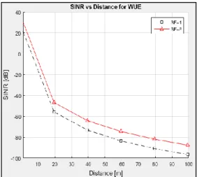
The SINR value at MUE and WUE have been simulated by using (5) and (7), respectively. Both SINR are investigated with different SF which are 1 and 8 to see the difference between lower SF with higher SF. In addition, both SINR have been investigated to see the effects of proposed with respect to the SINR. Figure 1 and Figure 2 show graphs of SINR vs Distance for MUE and WUE respectively, with the effect of SF which are 1 and 8. The graphs show that SINR value for both MUE and WUE decrease as the distance increase due to the values of SINR drop when the UEs move away from its serving BS.
In terms of different SF values on SINR, the results demonstrated that SF=8 gives higher SINR for both UEs compared to SF=1. It is because higher SF gives the higher signal’s resistance to interference than lower SF. Hence, improves the SINR at UEs. In addition, the SF is also known as processing gain. Higher value of the processing gain means the system increases the signal’s resistance to interference by spreading it across much greater number of frequencies (higher robustness against errors). On the other hand, lower processing gain value means the signal’s resistance to interference decreases. For MUE, the improvement percentage is 6.33% while the improvement percentage for WUE is 28.13%. From these results, higher SF which is 8 was chosen to use in this work to improve the SINR at Ues.
Figure 1. SINR vs Distance for MUE with the effect of SF
Figure 2. SINR vs Distance for WUE with the effect of SF
4.2. Effect of modified SINR expression with proposed
Next, the SINR of UEs was investigated with the effect of proposed α with values of 0.2, 0.4, 0.6 and 0.8. The SF value is fixed to 8 as it gives improvement on the SINR at UEs as proved in Section 4.1. Figure 3 and Figure 4 show graphs of SINR vs Distance for MUE and WUE respectively, with the effect of proposed α. When proposed α is applied to the SINR expression, the results illustrated that the SINR using proposed α have higher values in comparison to without using (standard DSSS). The reason is due to the proposed α affects the bandwidth capabilities, hence giving it much lower bandwidth to the system. When =1, it gives the chip rate value of the system. When is near to 0, it means the network bandwidth has been reduced, hence the SINR at UE can be improved. The bandwidth of the system although reduced but it is still acceptable because the bandwidth is no longer an important factor to be consider for implementing future technologies. It can also be solved by using priority on selected users and applications to make sure the users still can enjoy high performance [22]. Therefore, it was safely assumed that the proposed α increases the value of SINR. Among the α values, =0.2 gives the highest SINR when compared to others. By adding to original standard DSSS, the value of SINR improved as much as 4.69% for MUE and 17.94% for WUE.
Subsequently, the modified SINR expressions for both UEs were compared with previous method known as LAA. The SINR expression for LAA method can be defined in [25]. Figure 5 and Figure 6 show the graphs of SINR versus Distance for MUE and WUE, respectively compare to the LAA method. The results illustrated that the SINR using eDSSS have higher values in comparison to LAA method. This is because of chip rate value has reduced the overall bandwidth of the system. In addition, the high value of SF also provides a higher processing gain, higher robustness against errors and increases signal’s resistance to interference. For LAA method, the SINR considers the pathloss for both its serving and neighboring base stations. By using LAA, the reference distance for both users to the neighboring base stations are fixed to 1 meter [25]. When the UE is near to its neighboring base stations, it gave high interference to the user, hence reduces the SINR of UE. The SINR difference for MUE and WUE improved to 122 dB and 27 dB, respectively.
Figure 3. SINR vs distance for MUE of proposed α Figure 4. SINR vs distance for WUE of proposed α
Figure 5. SINR at MUE vs distance between eDSSS and LAA methods
Figure 6. SINR at WUE vs distance between eDSSS and LAA methods
5. CONCLUSION
Wi-Fi users in LTE-Wi-Fi networks especially at 2.4GHz are known to suffer from network degradation due to Wi-Fis’ subframes have been blocked all the time. In this work, by using eDSSS method with proposed α, it has improves the SINR values at MUE and WUE with 4.69% and 17.94%, respectively. Also, the proposed method gave higher SINR values at both MUE and WUE compared to LAA with 122dB and 27dB of SINR difference, respectively. For future work, the further investigation will considers both its serving and neighboring base stations by modelling the interference power using Pulse-Shaping Algorithm (PSA) method in order to further improve SINR at WUE. The PSA is a 3D interference power model that can reduce the interference power. It is well-known method used in coexistence network. By considering the method, it is expected to improve the SINR for both UEs in LTE-Wi-Fi networks and thus, reduces the co-channel interference.
REFERENCES
[1] A. Elnashar and M. A. El-Saidny, “Looking at LTE in Practice: A Performance Analysis of the LTE System Based on Field Test Results,” IEEE Vehicular Technology Magazine, vol. 8, no. 3, pp. 81–92, 2013.
[2] F. Z. Kaddour, “Optimization of Radio Resource Allocation in Uplink Green LTE Networks,” 2014. [3] Ericsson, “Ericsson Mobility Report,” Jun. 2014.
[4] P. Sharma, S. T. Valerrian Pasca, N. Kamath, and B. R. Tamma, “Velocity Based Dynamic Flow Mobility in Converged LTE/Wi-Fi Networks,” in 2016 22nd National Conference on Communication, NCC 2016, 2016.
[5] A. M. Cavalcante, E. Almeida, R. D. Vieira, S. Choudhury, E. Tuomaala, K. Doppler, F. Chaves, R. C. D. Paiva, and F. Abinader, “Performance Evaluation of LTE and Wi-Fi Coexistence in Unlicensed Bands,” in 2013 IEEE 77th Vehicular Technology Conference (VTC Spring), 2013.
[6] D. Lopez-Porez and H. Claussen, “Improved Frequency Reuse Through Sector Offset Configuration in LTE Heterogeneous Networks,” in 2014 IEEE International Conference on Communications (ICC), pp. 2338–2343, 2014.
[7] F. S. Chaves, E. P. L. Almeida, R. D. Vieira, A. M. Cavalcante, F. M. Abinader, S. Choudhury, and K. Doppler, “LTE UL Power Control for the Improvement of LTE/Wi-Fi Coexistence,” in 2013 IEEE 78th Vehicular Technology Conference (VTC Fall), Las Vegas, NV, pp. 1-6, 2013.
[8] 3GPP, “3GPP TR 36.889 : Study on Licensed-Assisted Access to Unlicensed Spectrum; (Release 13).”
[9] P.-H. Kuo, “New Physical Layer Features of 3GPP LTE Release-13,” IEEE Wireless Communications, no. August, pp. 4–5, 2015.
[10] R. Yin, G. Yu, A. Maaref, and G. Y. Li, “A Framework for Co-Channel Interference and Collision Probability Tradeoff in LTE Licensed-Assisted Access Networks,” IEEE Trans. Wirel. Commun., vol. 15, no. 9, pp. 6078–6090, 2016.
[11] G. Yoshizaki, K. Mori, K. Naito, and H. Kobayashi, “Enhanced Inter-Cell Carrier Aggregation with Spread Spectrum Technique for Next Generation Mobile Systems,” in 2014 21st International Conference on Telecommunications, ICT 2014, vol. 2014, pp. 379–383, 2014.
[12] D. Torrieri, “Principles of Spread Spectrum Communication Systems,” Springer New York, 2005.
[13] M. S. Amin, M. B. I. Reaz, J. Jalil, and L. F. Rahman, “Digital Modulator and Demodulator IC for RFID Tag Employing DSSS and Barker Code,” J. Appl. Res. Technol., vol. 10, no. 6, pp. 819–825, 2012.
[14] H. L. Sharma, A. R. Deshmukh, and N. G. Bawane, “Spread Spectrum Pattern and PN Sequence Retrieval in Wireless Ad Hoc Network: Design Approach,” in 2011 Second International Conference on Emerging Applications of Information Technology, 2011, pp. 391–394. 2011.
[15] W. Guo, W. M. Healy, and M. Zhou, “Impacts of 2.4-GHz ISM Band Interference on IEEE 802.15.4 Wireless Sensor Network Reliability in Buildings,” IEEE Trans. Instrum. Meas., vol. 61, no. 9, pp. 2533–2544, 2012. [16] G. Wang, G. Chen, D. Shen, X. Tian, K. Pham, and E. Blasch, “Spread Spectrum Design For Aeronautical
Communication System With Radio Frequency Interference Interferences Study For Aeronautical Communications,” in Digital Avionics Systems Conference (DASC), 2015 IEEE/AIAA 34th, pp. 1–11, 2015. [17] T. Dowluri and S. U. V. R. Kumari, “A Novel Approach for Frequency Hopping CDMA Technique,” Int. J. Adv.
Innov. Res., pp. 147–151, 2012.
[18] S. Furman and M. Gerla, “The Design of a Spatial Diversity Model to Mitigate Narrowband and Broadband Interference in DSSS Ad Hoc Networks,” in IEEE International Conference on Communications,2003 (ICC ’03), Anchorage, AK, vol. 2, pp. 1201-1205, 2003.
[19] Y. Jin, M. Al Ameen, and K. S. Kwak, “Interference Mitigation Study for Low Energy Critical Infrastructure Monitoring Applications,” in 2012 International Symposium on Communications and Information Technologies (ISCIT), pp. 962–966. 2012.
[20] J. Zyren, “Overview of the 3GPP Long Term Evolution Physical Layer,” 2007.
[21] O. Tirkkonen, “Principles of DS-CDMA,” TKK, Department of Communications and Networking, Aalto University.
[22] S. Martin, “From GSM to LTE-An Introduction to Mobile Networks and Mobile Broadband,” Third. Wiley, 2017. [23] 3GPP, “Technical Report 25.996,” 2011.
[24] ETSI, “TR 136 922 - V9.0.0 - LTE; Evolved Universal Terrestrial Radio Access (E-UTRA); TDD Home eNode B (HeNB) Radio Frequency (RF) requirements analysis (3GPP TR 36.922 version 9.0.0 Release 9),” 2010.
[25] Y. Li, J. G. Andrews, and T. D. Novlan, “Modeling and Analyzing the Coexistence of Wi-Fi and LTE in Unlicensed Spectrum,” IEEE Trans. Wirel. Commun., vol. 15, no. 9, pp. 6310–6326, 2016.