Technical Reports TR-37
Jeff Gray, Juha-Pekka Tolvanen, Jonathan Sprinkle (eds.)
6th OOPSLA Workshop on
Domain-Specific Modeling
(DSM’06)
October 22, 2006
Portland, Oregon USA
UNIVERSITY
OF JYVÄSKYLÄ
DEPARTMENT OF COMPUTER SCIENCE AND INFORMATION SYSTEMS
COMPUTER SCIENCE AND INFORMATION SYSTEMS REPORTS
Technical Reports TR-37
Jeff Gray, Juha-Pekka Tolvanen, Jonathan Sprinkle (eds.)
6th OOPSLA Workshop on
Domain-Specific Modeling
(DSM’06)
October 22, 2006
Portland, Oregon USA
October 2006
University of Jyväskylä
Department of Computer Science
and Information Systems
P.O.Box 35
FIN 40351 Jyväskylä
Finland
ISBN 951-39-2631-1 ISSN 1239-291X
Jyväskylä University Printing House, Jyväskylä, Finland 2006
i
Welcome to the Sixth OOPSLA Workshop on
Domain-Specific Modeling – DSM’06
PrefaceDomain-Specific Modeling (DSM) raises the level of abstraction beyond programming by specifying the solution directly using domain concepts. In many cases, final products can be generated automatically from these high-level specifications. This automation is possible because both the language and generators need fit the requirements of only one company and domain.
Industrial experiences from applying DSM consistently show it to be 5-10 times faster than current practices, including current UML-based implementations of MDA. As Booch* et al. have stated, "the full value of MDA is only achieved when the modeling concepts map directly to domain concepts rather than computer technology concepts." For example, DSM for cell phone software would have concepts like "Soft key button", "SMS" and "Ring tone", and generators to create calls to corresponding code components.
More investigation is still needed in order to advance the acceptance and viability of domain-specific modeling. This workshop, which is in its six incarnation at OOPSLA 2006, features research and position papers describing new ideas at either a practical or theoretical level. On the practical side, several papers in these proceedings describe application of modeling techniques within a specific domain. In addition to industrial projects, several authors from academia present research ideas that initiate and forward the technical underpinnings of domain-specific modeling. In particular, the 22 papers included in this proceedings highlight the importance of metamodeling, which significantly eases the implementation of domain-specific languages and provides support for experimenting with the modeling language as it is built (thus, metamodel-based language definition also assists in the task of constructing generators that reduce the burden of tool creation and maintenance). We hope that you will enjoy the workshop and find the information within these proceedings valuable toward your understanding of the current state-of-the-art in domain-specific modeling.
Jeff Gray, Juha-Pekka Tolvanen, Jonathan Sprinkle October 2006
*
Grady Booch, Alan Brown, Sridhar Iyengar, Jim Rumbaugh, and Bran Selic, MDA Journal, May 2004
22 October, 2006, Portland, Oregon USA
Program committee
Scott Ambler, IBMPierre America, Philips
Philip T. Cox, Dalhousie University
Krzysztof Czarnecki, University of Waterloo Andy Evans, Xactium
Jeff Gray, University of Alabama at Birmingham Jack Greenfield, Microsoft
Jürgen Jung, University of Duisburg-Essen Steven Kelly, MetaCase
Jürgen Kerstna, St. Jude Medical
Kalle Lyytinen, Case Western Reserve University Pentti Marttiin, Nokia
Birger Møller-Pedersen, University of Oslo Matti Rossi, Helsinki School of Economics Arturo Sanchez, University of North Florida
Jonathan Sprinkle, University of California, Berkeley Juha-Pekka Tolvanen, MetaCase
Markus Völter, independent consultant
Organizing committee
Jeff Gray, University of Alabama at Birmingham Jonathan Sprinkle, University of California, Berkeley Juha-Pekka Tolvanen, MetaCase
iii
Table of Contents
Welcome Message from the Organizers i
List of Program and Organizing Committees ii
Table of Contents iii-iv
Using Domain-Specific Modeling towards Computer Games Development Industrialization 1-14 André W. B. Furtado and André L. M. Santos
Building a Flexible Software Factory Using Partial Domain Specific Models 15-22 Jos Warmer and Anneke Kleppe
Conceptual design of web application families: the BWW approach 23-32 Roberto Paiano, Andrea Pandurino, and Anna Lisa Guido
Building End-User Programming Systems Based on a Domain-Specific Language 33-42 Herbert Prähofer, Dominik Hurnaus, and Hanspeter Mössenböck
Dart: A Meta-Level Object-Oriented Framework for Task-Specific Behavior Modeling by Domain Experts
43-55 Reza Razavi, Jean-François Perrot, and Ralph Johnson
Genie: a Domain-Specific Modeling Tool for the Generation of Adaptive and Reflective Middleware Families
56-66 Nelly Bencomo and Gordon Blair
Incremental Development of a Domain-Specific Language That Supports Multiple Application Styles
67-78 Kevin Bierhoff, Edy Liongosari, and Kishore Swaminathan
Programmatic Building of Models Just for Pretty Printing 79-86 Tero Hasu
Toward Families of QVT DSL and Tool 87-97
Benoît Langlois, Daniel Exertier, and Ghanshyamsinh Devda
Preserving Architectural Knowledge Through Domain-Specific Modeling 98-104 Femi G. Olumofin and Vojislav B. Miˇsi´c
Domain Model Driven Development of Web Applications 105-112 Dzenan Ridjanovic
Generative Programming for a Component-based Framework of Distributed Embedded Systems
113-122 Xu Ke and Krzysztof Sierszecki
Techniques for Metamodel Composition 123-139
Matthew Emerson and Janos Sztipanovits
On Relationships among Models, Meta Models and Ontologies 140-149 Motoshi Saeki and Haruhiko Kaiya
Roles in Software Development using Domain Specific Modelling Languages 150-158 Holger Krahn, Bernhard Rumpe, and Steven Volkel
Lightweight Domain-Specific Modeling and Model-Driven Development 159-168 Risto Pitkänen and Tommi Mikkonen
How to represent Models, Languages and Transformations? 169-176 Martin Feilkas
Model Integration in Domains Requiring User-Model Interaction and Continuous Adaptation of Metamodel
177-184 Peter Krall
The Practice of Deploying DSM Report from a Japanese Appliance Maker Trenches 185-196 Laurent Safa
A Model-Based Workflow Approach for Scientific Applications 197-203 Leonardo Salayandía, Paulo Pinheiro da Silva, Ann Q. Gates, and Alvaro Rebellon
Bootstrapping Domain-Specific Model-Driven Software Development within Philips 204-213 Hans Jonkers, Marc Stroucken, and Richard Vdovjak
Domain-Specific Model Composition Using a Lattice of Coalgebras 214-221 Jennifer Streb, Garrin Kimmell, Nicolas Frisby, and Perry Alexander
Using Domain-Specific Modeling towards Computer
Games Development Industrialization
André W. B. Furtado, André L. M. Santos Center of Informatics - Federal University of Pernambuco
Av. Professor Luís Freire, s/n, Cidade Universitária, CEP 50740-540, Recife/PE/Brazil
+55 (81) 21268430 {awbf,alms}@cin.ufpe.br ABSTRACT
This paper proposes that computer games development, in spite of its inherently creative and innovative nature, is subject of systematic industrialization targeted at predictability and productivity. The proposed approach encompasses visual domain-specific languages, semantic validators and code generators to make game developers and designers to work more productively, with a higher level of abstraction and closer to their application domain. Such concepts were implemented and deployed into a host development environment, and a real-world scenario was developed to illustrate and validate the proposal.
Categories and Subject Descriptors
D.1.7 [Programming Techniques]: Visual Programming.
D.2.2 [Software Engineering]: Design Tools and Techniques – Computer-aided software engineering (CASE), Software libraries.
General Terms
Design, Standardization, Languages.
Keywords
Computer games, domain-specific languages, visual modeling, software factories
1. INTRODUCTION
Digital games are one of the most profitable industries in the world. According to the ESA (Entertainment Software Association) [1], digital games (both computer and console games, along with the hardware required to play them) were responsible in 2004 for more than ten billion dollars in sales. These impressive numbers are a match even for the movie industry, while studies reveal that more is spent in digital games than in musical entertainment [2] The digital game industry, however, is as surrounded by success as it is continuously faced by challenges. Software development industrialization, an upcoming tendency entailed by the exponential growth of the total global demand for software, will present many new challenges to game development.
Studies reveal that there is evidence that the current development paradigm is near its end, and that a new paradigm is needed to support the next leap forward in software development technology [3]. For example, although game engines [4], state-of-the-art tools in game development, brought the benefits of Software Engineering and object-orientation towards game development automation, the abstraction level provided by them could be made less complex to consume by means of language-based tools, the use of visual models as first-class citizens (in the same way as source code) and a better integration with development processes.
development paradigm, based on craftsmanship, into a manufacturing process. The focus is on how visual domain-specific languages and related assets (such as semantic validators and code generators) can be used in conjunction within a software factory to make game developers and designers to work more productively, with a higher level of abstraction and closer to their application domain.
The remainder of this paper is organized as follows. Section 2 presents current digital games development tools and techniques, and explains their lack of industrialization. Section 3 introduces a game software factory named SharpLudus, which is targeted at a specific game genre. Section 4 details the SharpLudus Game Modeling Language, the most important factory asset, along with its related assets. Section 5 presents a case study named Ultimate Berzerk. Section 6, finally, concludes about the presented work and points out some future directions.
2. CURRENT TOOLS AND TECHNIQUES
A major evolution in game development technologies has occurred since its early days. Starting from assembly language, many tools and techniques evolved, culminating in game engines. This section describes the most used game development technologies and explains why they do not yet completely fulfill industrialization needs.
2.1 Multimedia APIs
Multimedia APIs (Application Program Interfaces), such as Microsoft DirectX [5] and OpenGL [6], are programming libraries that can be used to directly access the machine hardware (graphics devices, sound cards, input devices). Such APIs are not only useful for providing means to create games with good performance, but also for enabling the portability of computer games among devices manufactured by different vendors. Therefore, by using a Multimedia API, game programmers are provided with a standard device manipulation interface and do not need to worry about low-level peculiarities of each possible target device. Multimedia APIs set a new stage in game development, by empowering programmers with more abstraction to experience an easier game development process. They are heavily used today and certainly will last for a very long time, being used either directly or indirectly. Nevertheless, while these libraries handle almost all the desired low-level functions, the game itself still has to be programmed. The APIs provide features that are generic for computer games development and do not offer the abstraction level desired by game programmers. For example, they do not provide features to trigger the transition between game states (phases), entity behavior modeling or artificial intelligence. In other words, the semantic gap between game designers and the final code remains too high if multimedia APIs are the only abstraction mechanism used.
Besides that, interaction with such APIs can only be done programmatically, not visually. This approach may prevent automation and productivity in the execution of some tasks (such as specifying the tiles of a tiled background map), which would have to be executed by exhaustive “copy and paste” commands and through counter-intuitive actions.
2.2 Visual Game Creation Tools
With the intention to simplify game development and make it more accessible to a broader range of communities, visual game creation tools were created and soon became very popular. They aim at creating complete games with no programming at all, sometimes by just clicking
with the mouse. The end user is aided with graphical and easy-to-use interfaces for creating game animations, defining entity behavior, the flow of the entire game and to add sound, menus, text screens and other resources to the game.
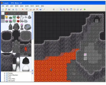
A visual game creation tool can be either generic or focused on the creation of games belonging to a specific game genre, such as first-person shooters, role playing (RPG), adventure games and so on. This last category includes one of the most popular visual game creation tools: RPG Maker [7], presented in Figure 1.
Figure 1. RPG Maker
Being able to finish the creation of a complete game with a few mouse clicks is very impressive indeed. However, although this sounds wonderful at first, the possibilities turn out to be limited. Some types of games can certainly be made, but this approach does not seem adequate for serious games [8]. Visual game creation tools currently do not address the complexity required by the creation of more sophisticated games, and this is reflected by the lack of their adoption by the game industry. Despite being very popular, most users of such tools are beginner and amateur game designers and programmers.
Visual game creation tools try to address such a problem by offering to users script languages, targeted at allowing more complex behaviors to be specified. However, while such languages certainly provide more power to visual game creation tools, they require end-users to learn a new language (perhaps their first language) and to have some programming skills. This may diverge with the original purpose of such tools (to be “visual programming” environments). Some may say that these built-in languages are not intended to be used by all users, but only by advanced users. But once earning programming expertise, however, users might prefer to have the benefits of true object-oriented programming languages, with the support of robust integrated development environments with full editor and debugging support, instead of working with error-prone scripting languages inside an environment which was not originally conceived for codification.
Besides that, development productivity is much more than having script keywords highlighted. It is composed by a set of complementary concepts, such as refactoring, code and modeling synchronization, test automation, configuration management, quality assurance, real-time project monitoring, domain-specific guidance and organizational process integration, just to mention a few.
computer games development. An engine can be seen as a reusable API, which gathers common game development foundations (entity rendering, world management, game events handling, etc.) and provides to developers a programmatic interface through which game behavior can be specified. In other words, developers can be more focused on game-specific features, such as its programming logic, intelligence, art and so on.
Differently from the scenario where multimedia APIs are called directly by the computer game code, developers using a game engine are abstracted from low-level game implementation details, while still not being restricted to the limitations of an exclusively visual programming environment. As a matter of fact, the basic game functionalities provided by game engines are built on top of multimedia APIs. Examples of popular game engines are OGRE [9] and Crystal Space [10].
As with visual game creation tools, game engines can be either generic or targeted at a specific game genre. However, in order to be more effective, even generic game engines narrow their target domain by addressing only a subset of all possible computer game genres (for example, a 3D game engine has many specific issues different from a 2D isometric game engine). In fact, the main advantage of using a game engine is that, if it was built in a modular architecture, it can be reused to create a great diversity of games, which consume only the necessary game engine modules [11].
Game engines are the state-of-the-art tools in computer games development. By providing more abstraction, knowledge encapsulation and a reusable game development foundation, they allowed the game industry to reach an unparalleled productivity level. However, as with any technology, some drawbacks can be identified.
First of all, due to the inherent complexity of game engines, it should be noticed that the learning curve for mastering these tools is somewhat high. The demands for understanding the game engine architecture, interaction paradigm and programming peculiarities can turn their use into an unintuitive experience at first. That is the reason why many of today’s game engines still present complexity and lack of usability as one of their most cited deficiencies. Second, using a game engine may involve considerable costs, such as acquisition costs, training costs, customization costs and integration costs [12]. If the discussion is raised from the game developer point-of-view to the game engine developer point-of-view, additional needs for a considerable amount of resources can be identified. Since a diversity of requirements has to be satisfied, creating a game engine is a very complex and expensive task, demanding a substantial infra-structure.
In addition, one of the major difficulties in game engine development is the industrial secrecy. Since such projects involve great investments, many organizations hide their architectures and tools in order to have some advantage over their competitors [13] (for example, it may be difficult to find comprehensive studies about the applicability of design patterns in game engines [11]). Public knowledge regarding the subject, therefore, is only available through open source and academic initiatives. However, it has not been a long time since such initiatives were born, and today’s game engine developers are far from having something like “game engine workbenches” to aid the creation of such tools.
2.4 Game Development onto the Next Stage
In general, game development evolution has been compliant with one of the most important software development tendencies: defining a family of software products, whose members vary, while sharing many common features. According to Parnas [14], such a family provides a context in which the problems common to the family members, such as games belonging to a specific genre, can be solved collectively.
If automation in software development is further investigated, it is possible to notice that game engines can still contribute even more to automation in game development. Roberts and Johnson [15], for example, described a recurring pattern that reveals how software development automation, in general, is carried out:
• After developing a number of systems in a given problem domain, a set of reusable
abstractions for that domain is identified, and then a set of patterns for using those abstractions is documented.
• Then a runtime is developed, such as a framework or server, to codify the abstractions and patterns. This allows the creation of systems in the domain by instantiating, adapting, configuring, and assembling components defined by the runtime.
• Then languages are defined and tools are built to support the runtime, such as editors,
compilers and debuggers, which automate the assembly process. This helps a faster response to changing requirements, since part of the implementation is generated, and can be easily changed.
Game engines are situated in the second of these three “pattern-runtime-language” stages. However, as Roberts and Johnson point out, although a framework (such as a game engine) can reduce the cost of developing an application by an order of magnitude, using one can be difficult. Mapping the requirements of each product variant onto the framework is a non-trivial problem that generally requires the expertise of an architect or senior developer. Language-based tools (the third stage) automate this step by capturing variations in requirements using language expressions, encapsulating the abstractions defined by a framework, helping users think in terms of the abstractions and generating framework completion code. Language-based tools also promote agility by expressing concepts of the domain (such as the properties or even features of computer games) in a way that customers and users better understand, and by propagating changes to implementations more quickly. Aligned with the creation of language-based tools, an emerging tendency is to make models first-class citizens for game development, in the same sense that source code already is an essential part of game development. Models can be described by visual domain-specific languages (DSLs) [16], providing a richer medium for describing relationships between abstractions and giving them greater efficiency and power than source code. By using a visual DSL, models can be used not only as documentation but as input that can be processed by tools in other stages of the development process, promoting more automation.
There is evidence, therefore, that game engines can be used together with domain-specific processes, patterns, frameworks, tools and especially languages to create a software factories approach that will situate game development in an industrial stage, by reusing these assets systematically and automating more of the software life-cycle.
3. SHARPLUDUS SOFTWARE FACTORY
In order to illustrate how games development can be turn into a more productive and automated process by means of software industrialization, a software factory named
of multiple, connected rooms or screens, involving an objective which is more complex than simply catching, shooting, capturing, or escaping, although completion of the objective may involve several or all of these. More information regarding the chosen domain is presented in Table 1.
Table 1. SharpLudus Product Line Definition
Feature Description
Dimensionality Two-dimensional (2D). World rooms are viewed from above.
User interface
Information display screens containing textual and/or graphical elements are supported. HUDs (heads-up display) can also be
configured and displayed.
Game flow
Each game should have, at least, a main character, an introduction screen, one room and a game over screen (this last one is reached
when the number of lives of the main character becomes zero).
Sound/Music
Games will be able to reproduce sound effects (wav files) as event reactions. Background music (mp3 files) can be associated with
game rooms or information display screens.
Input handling Keyboard only
Multiplayer
Online multiplayer is not supported by the factory. Event triggers and reactions can be combined, however, to allow two-player
mode in a single computer.
Networking High scores can be uploaded to and retrieved from a web server.
Artificial Intelligence
Enemies can be set to chase the player within a room. More elaborated behaviors can be created visually by combining predefined event triggers and event reactions, or programmatically
by developers.
End-user editors Not supported by the factory. Once created, a game cannot be customized by its players.
Target Platform(s) PCs running Microsoft Windows 98 or higher
The SharpLudus software factory provides to developers two visual domain-specific languages (DSLs) as assets. The first one is the Game Modeling DSL, which together with a room designer and an info display designer allows the specification of the game states flow (info display screens, rooms and their exit conditions).
The second domain-specific language is the HUD Creation DSL, which allows developers to specify how useful game information (score, remaining lives, hit points, etc.) will be presented to the player by means of a heads-up display. Both DSLs are provided with validators to ensure that semantic errors are caught in design time and shown in the IDE Error List.
By using the factory DSLs, game designers can create a detailed game specification. However, contrary to common game development approaches, such a specification is a set of “live artifacts”. This means that they are not only used for documentation, but they can be transformed into other artifacts by means of automation assets. For example, the VSTO [17] technology is used to create a User Manual skeleton with information extracted from the game specification, while code generators associated to the DSLs can be used to
automatically create the majority of the game implementation code. Developers, however, can add their own code to the solution since the factory generated code provides extensibility mechanisms such as partial classes1 and classes which are just ready for customization (for
example, special classes for providing custom event triggers and custom event reactions). Both the factory generated code and the developer added code interacts with a game engine, which consumes the DirectX Multimedia API. Once the solution implementation is compiled, the factory generates the game executable file and a XML configuration file, through which a high scores web server address and custom developer configuration can be specified. Finally, built-in factory organizational assets, such as the runtimes of the game engine and the multimedia API chosen, are automatically made available by the factory. In order to illustrate how domain-specific modeling is carried out through the SharpLudus factory, Section 4 details the SharpLudus Game Modeling DSL and Section 5 explores some of its designers through the development of a real-world example.
4. GAME MODELING DSL (SLGML)
The SharpLudus Game Modeling Language (SLGML) is a visual DSL through which the game designer can specify the main game configuration (resolution, screen mode, etc.), game states (rooms and information display screens) and their flow, exit conditions and properties. The SLGML underlying concepts are also manipulated by many factory designers (event designer, entity designer, sprite designer, etc.).
According to Deursen, Klint, and Visser [16], the development of a domain-specific language typically involves the following tasks:
• [Analysis] (1) Identify the problem domain; (2) Gather all relevant knowledge in this
domain; (3) Cluster this knowledge in a handful of semantic notions and operations on them; (4) Design a DSL that concisely describes applications in the domain.
• [Implementation] (5) Construct a framework (library) that implements the semantic
notions; (6) Design and implement a compiler that translates DSL programs to a sequence of framework calls. Obs: considering language workbenches and visual modeling, Fowler [18] suggests an additional task to this stage: (7) the creation of a visual editor to let developers to graphically manipulate the DSL. Considering a software factory context, this research also suggests an additional step: (8) the creation of semantic validators to identify modeling errors in design time.
• [Use] (9) Write DSL programs for all desired applications and compile them.
Tasks (1) and (2) are performed as part of the software factory product line definition and product line design. The next subsections detail the other tasks, aside from task (9), which will be explored by means of a case study presented in Section 5.
4.1 Concepts Design
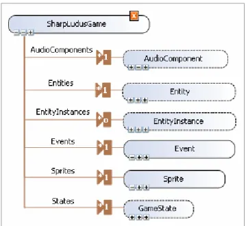
The SharpLudusGame is the root domain concepts of the SLGML DSL. As Figure 2 presents, it is related to six top-level elements, which will not be deeply detailed due to space constraints but are explained below:
• AudioComponent: an abstract concept representing every sound that can be
reproduced in a SharpLudus game. It is specialized by SoundEffect and BackgroundMusic concepts.
1
The concept of partial classes makes it possible to split the implementation of a single class in two files.
MainCharacter, NPC (non-playable character) and Item concepts.
• EntityInstance: represents an instance of an entity, containing information such as position, speed, number of remaining hit points, etc.
• Event: represents a special condition that occurs to a SharpLudus game, fired by one
or more Triggers (such as “collision between the main character and a specific item”), and that cause one or more Reactions (such as “add item to main character inventory”). The CustomTrigger and CustomReaction concepts, which inherit from Trigger and Reaction respectively, make it possible to create custom-made events.
• Sprite: represents an animation that can be assigned to entities (such as “main
character walking”, “main character jumping”, etc.). It is composed by a Frame collection and it may loop after it ends.
• GameState: abstract concept which represents the game flow. It is specialized by InfoDisplay and Room concepts. InfoDisplays are used to display information (textual or graphical) on the screen, containing a Purpose attribute to indicate if it is an introduction, game over or ordinary information display screen (such as a menu, credits or instructions screen). Finally, each GameState contains an ExitCondition collection, which tells when the game should move from one state to another (e.g., when a key is pressed).
Figure 2. Top-level SLGML concepts
4.2 SLGML Syntax
Language syntax defines how the language elements appear in a concrete, human-usable form. Visual languages syntax is not only purely textual, combining graphics, text and conventions by which users may interact with the graphics and the text under the auspices of tools. Table 2 presents the visual syntax elements of SLGML.
Table 2. SLGML Visual Syntax
Graphical
Representation Description
InfoDisplay: An information display screen is represented by a picture (shown in the left), and contains a textual
decorator on its outer top, describing its name.
Intro Purpose Decorator: This image decorator is applied to an info display, on its inner top, if the info display
purpose is Intro.
Game Over Purpose Decorator: This image decorator is applied to an info display, on its inner top, if the info
display purpose is GameOver.
Room: A game room is represented by a picture (shown in the left) and contains a textual decorator on its outer top,
describing its name.
Transition: State transitions are visually represented as black arrows.
4.3 Semantic Validators
Besides aiding game designers with visual edition features, SLGML modeling experience also ensures that the DSL semantics are respected by them. This is done through semantic validators. The list below shows some examples of semantic rules associated with SLGML and enforced by means of validators:
• A game state transition must have at least one exit condition;
• A SharpLudus game should contain one main character;
• A SharpLudus game should contain only one introduction InfoDisplay; • A SharpLudus game should contain only one game over InfoDisplay; • An entity should contain at least one sprite;
• All game states should be reachable.
consumes a simple game engine developed with DirectX which was specially created for the factory. In other words, the generator receives a SLGML diagram as input and generates the following C# classes as output:
• AudioComponents, responsible for providing sound effect and background music objects via C# properties compliant to the Singleton [20] design pattern.
• Sprites, responsible for providing sprite objects via C# properties. The Singleton design pattern is not used in this case, since each sprite must be unique due to its own animation information, such as its current frame.
• One class for each Entity concept specified by the game designer. Such a class inherits
from the Item, MainCharacter or NPC game engine classes.
• EntityInstances, responsible for providing entity instance objects via C# properties compliant to the Singleton design pattern.
• States, responsible for providing room and information display screen objects via C# properties compliant to the Singleton design pattern.
• The main game class, whose name corresponds to the Name property of the SharpLudusGame root concept. Such a class inherits from the Game game engine class. The code generator also creates a method in this class named InitializeResources, where the game configuration is set and game events are registered.
• Program, which contains the Main method and is responsible for instantiating and running the game.
Besides the generated classes, the IDE project additionally provides two initial classes which are not re-generated: CustomTriggers and CustomReactions. Developers should add their own methods to these classes in order to implement custom triggers and custom actions specified by the game designer in the SLGML model.
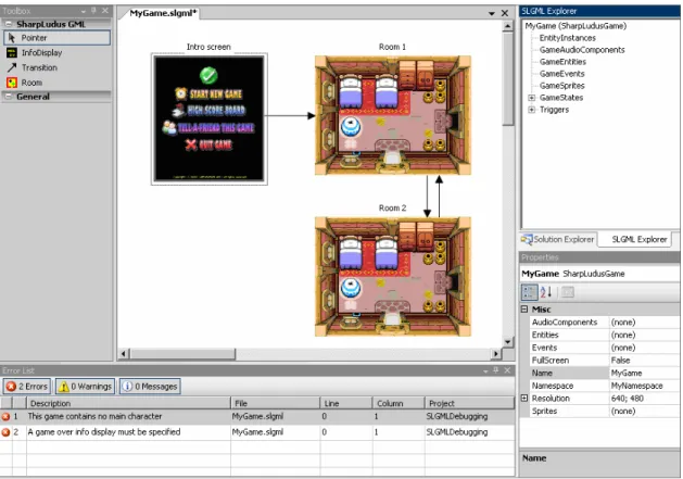
Figure 3 presents the complete SLGML modeling experience, hosted in the Visual Studio .NET development environment [21]. The Toolbox (at the left) presents some domain concepts that can be dragged and dropped to the SLGML designer (at the middle). The Error List (at the bottom) presents errors risen from semantic validators. The Properties window (at the right bottom) makes it possible to edit properties of the selected item in the diagram, eventually launching factory designers (sprite designer, entity designer, room designer, etc.). By using menu commands, users can launch the code generator as well as create their own code.
5. CASE STUDY: ULTIMATE BERZERK
This section presents the creation of a real-world adventure game named Ultimate Berzerk, which illustrates the use of the SharpLudus software factory. In Ultimate Berzerk, the player controls a main character, using the arrows key, to move around a maze composed by connected rooms. Once the player collects a special item (named Weapon), the spacebar can be used to shoot fireballs against enemies. Enemies may have special behaviors (not originally provided by the factory). The goal of the game is to collect the Diamond item and find the exit sign. A screenshot of the game is presented in Figure 4.
Figure 3. Complete SLGML modeling experience
Figure 4. Ultimate Berzerk screenshot
5.1 Designing the Game
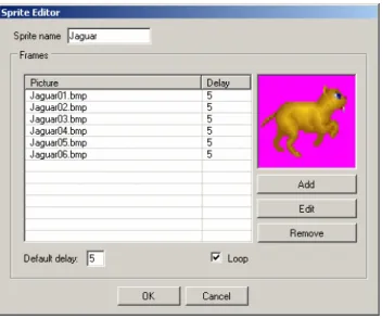
By modeling a SLGML diagram and launching factory designers from the Properties window, the game designer is able to visually create the majority of the game: sprites, entities, events, audio components, etc. For example, Figure 5 presents one of the screens of the sprite designer. This designer is launched from the Sprites property of a SharpLudus game and makes it possible for the game designer to specify frames and information such as if the animation will loop or not.
Figure 6, on the other hand, presents the room designer, where previously created sprites can be assigned to a room as tiles and entity instances (such as enemies and items) can be added to rooms based on previously created entities.
Figure 6. Room Designer
5.2 Custom Developer Code
Some NPCs (non-playable characters) of Ultimate Berzerk have special behaviors. For example, the enemy known as Diamond Guardian (shown in Figure 4) has a special movement in which it is bounced by room tiles of type “rock”. In order to implement such behavior, factory users only need to add a class to the project named DiamondGuardian, mark it as “partial” and override the desired methods. This will make the final class to be the combination of the user DiamondGuardian class with the factory generated DiamondGuardian class.
It is worth noticing that when adding their own code, users will have full IDE editing and debugging support, as well as be able to make complex API calls, such as requesting information from a web service or accessing a database, for example.
5.3 Discussion: Factory Effectiveness
Although Ultimate Berzerk is a relatively simple game, with a few rooms to be investigated by the main character, its development explored many interesting SharpLudus software
factories assets and features that illustrate how the factory can be used to create real-world games. Extending Ultimate Berzerk to a game with a better game-play and replay value is just a question of adding more model elements which reflect the creativity of the game designer. The automation and productivity provided by the SLGML modeling experience, its code generator and consumed game engine is evident: in less than one hour of development effort, 16 classes and almost 3900 lines of source code were automatically generated for the development team. What is most important is that such lines of source code mainly present routine, boring and error-prone tasks, such as assigning pictures to frames, frames to sprites, sprites to entities, entities to rooms, rooms to the game, events to the game and so on.
By using the SharpLudus software factory, especially the visual designers, the development team experience was made more intuitive and accurate. At the same time, when more complex behavior was required (such as specifying the Diamond Guardian movement) the factory was flexible to allow developers to add their own code to the solution, using all of the benefits of an object-oriented programming language and being aided by IDE features such as editor support, debug support and so on. This contrasts the development experience of visual-only game development tools, where weak script languages should be used under an environment which was not originally conceived for codification.
Considering the generated code along with the consumed game engine, it can be concluded that the SharpLudus software factory is able to provide, in one hour, a development experience which would require, from scratch, the implementation of 61 classes and more than 6200 lines of source code.
6. CONCLUSIONS AND FUTURE WORK
This paper presented a study, illustrated with a real example, of how digital games development can better exploit an upcoming tendency: software industrialization. Different aspects were encompassed by such a study, being the development of a visual domain-specific language the most appealing subject.
Since the proposed approach and tools are focused on a specific domain, they may not be suitable to other types of game development contexts. Therefore, one interesting future work is the creation, based on previously acquired knowledge, of other factories targeted at other game genres, such as racing games or first-person shooters. Some domain concepts, factory designers, semantic validation rules and excerpts of the code generator may be reused, while others will need to be recreated.
Extending the SharpLudus software factory architecture and code generator to support the creation of games targeted at mobile devices, such as cell phones, seems to be quite appealing, since a recognized issue is that porting the same game to different mobile phone platforms is a burdensome and error-prone task. In such a case, once a code generator is implemented for each platform, all platforms would be able to share a single game model (specified with the SLGML visual domain-specific language) and maintenance would be made much simpler.
While the results obtained so far empirically shows that the SharpLudus factory is indeed an interesting approach, it is important to notice that deploying a complete software factory is also associated with some costs. Return of investment may arise only after a certain amount of games are produced. Besides that, despite being easy to use, software factories are complex to develop. They will certainly require a mindset evolution of the game development industry. A final remark is that the presented proposal alone will not ensure the success of game development. In fact, no technology is a substitute for creativity and a good game design.
the game or its constituent technologies, should be the final focus of every new game development endeavor.
REFERENCES
[1] Entertainment Software Association, Essential Facts about the Computer and Video Game Industry, 2005.
[2] Digital-lifestyles.info, Men Spend More Money on Video Games Than Music: Nielsen Report, http://digital-lifestyles.info/display_page.asp?section=cm&id=2091.
[3] Greenfield, J. et. al., Software Factories: Assembling Applications with Patterns, Models, Frameworks, and Tools, Wiley & Sons, 2004.
[4] Zerbst, S., Duvel O., 3D Game Engine Programming, Course Technology PTR, 1st edition.
[5] Microsoft DirectX, http://www.microsoft.com/directx. [6] OpenGL, http://www.opengl.org.
[7] RPG Maker XP, http://www.enterbrain.co.jp/tkool/RPG_XP/eng/index.html.
[8] Wiering, M. The Clean Game Library, MSc dissertation, University of Nijmegen, 1999. [9] Ogre3d.org, OGRE 3D: Open Source Graphics Engine, http://www.ogre3d.org.
[10]Sourceforge.net, Crystal Space 3D, http://crystal.sourceforge.net.
[11]Rollings, A.; Morris, D.; Game Architecture and Design, The Coriolis Group, 2000. [12]Albuquerque, M. Revolution Engine: 3D Game Engine Architecture, BS conclusion
paper, Federal University of Pernambuco, 2005.
[13]Rocha, E. Forge 16V: An Isometric Game Development Framework, MSc dissertation, Federal University of Pernambuco, 2003.
[14]Parnas, D. On the Design and Development of Program Families, IEEE Transactions on Software Engineering, March 1976.
[15]Roberts, D.; Johnson, R. Evolving Frameworks: A Pattern Language for Developing Object-Oriented Frameworks, Proceedings of Pattern Languages of Programs, 1996. [16]Deursen, A.; Klint, P.; Visser, J. Domain-Specific Languages: An Annotated
Bibliography, http://homepages.cwi.nl/~arie/papers/dslbib/. [17]MSDN.com, VS Tools for Office Developer Portal,
msdn.microsoft.com/office/understanding/vsto/default.aspx.
[18]Fowler, M. Language Workbenches: The Killer-App for Domain Specific Languages?, www.martinfowler.com/articles/languageWorkbench.html.
[19]Microsoft.com, C# Developer Center, http://msdn.microsoft.com/vcsharp/.
[20]Gamma, E.; Helm, R.; Johnson, R.; Vlissides, J. Design Patterns: Elements of Reusable Object-Oriented Software, Addison-Wesley Longman, 1998
[21]MSDN.com, Visual Studio 2005 Team System: Overview,
http://msdn.microsoft.com/library/default.asp?url=/library/en-us/dnvsent/html/vsts-over.asp.
Building a Flexible Software Factory Using Partial
Domain Specific Models
Jos Warmer1, Anneke Kleppe23 1Ordina SI&D, The Netherlands
[email protected] 2University Twente, Netherlands
Abstract. This paper describes some experiences in building a software factory by defining multiple small domain specific languages (DSLs) and having multiple small models per DSL. This is in high contrast with traditional approaches using monolithic models, e.g. written in UML. In our approach, models behave like source code to a large extend, leading to an easy way to manage the model(s) of large systems.
1 Introduction
A new trend in software development is to use model driven techniques to develop software systems. Domain specific models (DSMs), domain specific languages (DSLs), and the trans-formations from the DSMs to code need to be carefully designed to make them really useable. An obvious observation is that one single model (in a single file or single repository) will not suffice for describing a complete application. Such a model would be too large to handle; it would be unreadable and thus not understandable. Although obvious, this is something that has not been acknowledged in the modelling world. Companies that apply model driven devel-opment on a large scale are having problems in managing models that are sometimes over 100 MB size. We therefore argue for building smaller, partial models, each of which is part of a complete model. This is much like the way a code file for a class is part of the complete source code for the application. Each partial model may be written in either the same or a different DSL, thus using the advantage of the fact that a DSL is designed to solve one specific part of a problem as good as possible.
In this paper we show how partial models can be used to build large, complex applications. We also show the consequences of this approach on the DSL definitions and their accompany-ing model-to-code transformations. We will also show how managaccompany-ing models for large appli-cations is simplified by using partial models.
This paper is based on the industrial experience of one of the authors with building the SMART-Microsoft Software Factory at Ordina, a model driven development software factory using the Microsoft DSL Tools. At the time of writing this software factory included four dif-ferent DSLs. Typically several dozens of DSMs are created in a project that utilizes this soft-ware factory. Although the experience was gained using the Microsoft DSL Tools, the approach can be applied in other environments (like e.g. Eclipse GMF).
This paper is structured as follows. Section 2 explains in short the development process when using a model driven software factory. Section 3 introduces the concept of partial
mod-3. The author is employed in the GRASLAND project funded by the Dutch NWO (project number 612.063.408).
plains different forms of code generation from partial models.
2 The Software Development Process
The traditional development process, not using models, DSLs, or model transformations, can (simplified) be described as follows. Decide on the architecture of the application (1). Design the application (2). Write the code, compile it, and link it (3). Run the application (4).
The model driven software factory process, as introduced in [GSCK04], using DSLs and model transformations, works in a different way. First, the software factory itself is designed as follows:
1. Decide on the architecture of the application. 2. Design the DSLs for this architecture
3. Write the transformations for these DSLs
The system developer does not need to determine the architecture any more, but starts directly with modelling the application:
1. Model the application. 2. Transform the models.
3. Write additional code (if required).
4. Compile and link the code, and run the application
This process is often done iteratively, meaning that after running the application in step 4 you go back to step 1 and start modeling the next part of the application. The development of the software factory is also done iteratively, but in the context of this paper that is not relevant. Also note that a software factory is more than just a collection of DSLs, however this paper focuses on the DSL aspect, and what’s more we focus on the first part of the process: how to build a collection of DSLs and their transformations.
3 Developing a Flexible Software Factory
The first step when developing a model driven software factory, is to determine the architec-ture of the applications that you are going to build with the software factory. Is it, for instance, a web-based, administrative application or is it a process control system? The answer to this question determines the architecture. From the architecture we derive which DSLs are to be defined for modelling the application.
The SMART-Microsoft Software Factory is targeting web-based, administrative applica-tions, of which the architecture is shown in Figure 1. Based on this architecture we have de-fined four different DSLs, each of which corresponds to a part of the architecture. We recognise the following domains: the Web Scenario DSL for the Presentation layer, the ness Class DSL for the Business classes, the Services DSL for the Service Interface and Busi-ness Processes, and the Data Contract DSL for the Data Contract. There is no DSL corresponding to the Data layer, because this layer is completely generated from the Business Class DSL. A developer who wants to build a compete system will use all DSLs together.
The different DSL are mostly independent, therefore it is possible to use a subset of the DSLs provided. We can also combine the DSLs in a different way. For example, we are plan-ning to develop a DSL for building Windows user interfaces, which can then be used instead of the current Web Scenario DSL. This allows us to flexibly evolve the software factory.
3.1 Goals for Domain Specific Languages
1. A model is always executable in the sense that every aspect of a model is used to gen-erate code. We do not consider models used purely for design or documentation, these can be built effectively with UML or tools like Visio.
2. A concept only becomes part of a DSL if it is easier or less work to model it than to code it. This keeps the number of concepts small and ensures that the DSL is very pro-ductive.
3. Models (or better said the code generated from the models) are meant to be extended by code.
3.2 Introducing Partial Models
When using the software factory to build an application, a developer determines the number and kind of DSMs that need to be built. One possibility, which we have seen used at several places, is to create one DSM per DSL. This would mean that we have four DSMs for each ap-plication. Still, for a large application this still does not scale up. For instance, if we have one DSM for the complete Web Scenario Domain, this will become an incredibly large model for any real application. The model would contain many Web Scenario elements, which each con-sists of a set of Web Pages and Actions. A model of such size is not readable, and certainly not understandable.
Working with one large model also introduces many practical problems relating to manag-ing such a model in a multi-user environment. Experience with traditional UML tools has
'DWDVRXUFHV 6HUYLFHV 3UHVHQWDWLRQOD\HU %XVLQHVVOD\HU 8VHUV 8VHU,QWHUIDFHFRPSRQHQWV 8VHU3URFHVVHV %XVLQHVV3URFHVVHV 'DWD$FFHVV/RJLF&RPSRQHQWV 6HUYLFH$JHQWV 'DWD6HUYLFH$JHQWV %XVLQHVV&ODVVHV 'DWDFRQWUDFW '72 9LHZ'72 'DWDVRXUFHV 6HUYLFHV 3UHVHQWDWLRQOD\HU %XVLQHVVOD\HU 'DWDOD\HU 8VHUV 8VHU,QWHUIDFHFRPSRQHQWV 'DWDFRQWUDFW 8VHU3URFHVVHV 6HUYLFH,QWHUIDFHV %XVLQHVV3URFHVVHV %XVLQHVV:RUNIORZV 6HUYLFH$JHQWV %XVLQHVV&ODVVHV 'DWD$FFHVV/RJLF&RPSRQHQWV 'DWD6HUYLFH$JHQWV '72 9LHZ'72
Fig. 1 The Web Application Service Architecture
tiple persons to work simultaneously on a model, the model must usually be divided before-hand in non-overlapping slices and the developers must be very disciplined while working with the tools.
The solution to this problem that we present here is to use multiple DSMs per DSL. We call these models partial models, because they do not represent the complete system. Each partial DSM is stand alone and can be used in isolation. In the case of the Web Scenario DSL, the DSL has been designed such that each DSM contains not more than one Web Scenario. If an appli-cation needs e.g. twenty Web Scenarios, twenty Web Scenario DSMs will be created. As a di-rect consequence of this choice each partial DSM has some unique and useful properties: • One partial DSM can be created and edited stand alone by one user.
• The partial DSM is the unit of version control, and when the DSM is stored on file, ordi-nary version control systems provide ample possibilities for version control.
Our approach fits very well with the structuring of the Microsoft DSL Tools that we have been using, in which one model is stored in one file. Also, in the Microsoft DSL Tools one model is identical to one diagram, and should therefore remain small. In the remainder of this paper all DSMs are partial models, the DSLs are designed to support this.
4 Combining Partial DSMs using References
Allowing partial DSMs has direct consequences for the way that a DSL is defined. One such consequence is that we need a way to define references between DSMs. This section describes the ins and outs of references.
4.1 References between Partial DSMs
A model element from a partial DSM may be referenced in another partial DSM just like class-es and their operations may be referenced in a code file. To ensure that a DSM remains a stand alone artifact, references are always modelled explicitly and are always by name. There are no hard links between different DSMs, otherwise we would end up with one monolithic model again. To accommodate this we have introduced a metatype Reference to ModelElement for each modelelement that we want to refer to in each of our DSLs. This metaclass may be sub-classed to create a reference to a particular type of modelelement. Thus, a model element in a DSM may be of type Reference to BusinessClassDto, holding the name (or path) of a business class in another DSM.
References may link DSMs written in the same DSL, e.g. a Reference to WebScenario in a Web Scenario DSM, or they may link DSMs written in different DSLs, e.g. a Reference to
BusinessClassDto in a Web Scenario DSM, that refers to a modelelement in a Data Contract
DSM. An example of the first can be found in DSM 1 in Figure 2, an example of the second can be found in DSM 2.
4.2 Checking References
In a complete application the references within the DSMs should all be valid, e.g. the referred
WebScenario in Figure 2 must be defined in another DSM. For this purpose we have developed
inter-DSM validation support. With one button, a user can do a cross-check on all references to check whether the referred elements exist. This validation is based on a small run-time com-ponent, which is populated from the DSMs in the developers workspace. This component is similar to a symbol table in a compiler and only holds the minimum information needed for validation purposes.
Note that a single DSM is still valid if a reference does not exist, but the collection of DSMs is not complete. The DSM with the unresolved reference can still be edited, checked in, and its model elements can be referred to by other DSMs, etc.
4.3 Dealing with Changes in References
A change in the name of a referred model element is allowed, but will make existing refer-ence(s) dangling. This is an inherent feature, following directly from the way DSLs are de-signed. Tool support for coping with this kind of changes is not within the scope of language definition, instead it should be provided by the IDE. There are various options for dealing with dangling references:
• No support: the inter-DSM validation will result in an error message and the developer has to “repair” the dangling reference.
• Refactoring support: the user may explicitly perform a name change of the referred model element as a refactoring. The IDE will find all references, and change them to refer to the new name.
• Automatic support: when the user changes the name of a referred element, all references will change automatically.
Having no support at all does work, but is cumbersome. Automatic support has the problem that the developer does not know where automatic changes take place and he might therefore encounter unexpected results. In the Plato model driven environment that we have built in the
ZHEVFHQDULR!! 2UGHU3URGXFW ZHEVFHQDULRUHIHUHQFH!! 6HOHFW3URGXFW :HE6FHQDULR'60 DFWLRQ!! )LQDOL]H2UGHU ZHEVFHQDULR!! 6HOHFW3URGXFW :HE6FHQDULR'60 %XVLQHVV&ODVV'WR!! 3URGXFW 1DPH6WULQJ 3ULFH $PRXQW &RORU &RORU7\SH DFWLRQ!! 8VHUJLYHVQDPH DQGDGGHVV DFWLRQ!! 6KRZOLVWRISURGXFWV %XVLQHVV&ODVV'WR 5HIHUHQFH 3URGXFW DFWLRQ!! 6HOHFW2QH3URGXFW 'DWD&RQWUDFW'60
Fig. 2 Example of references between partial models
cause the changes were not controlled.
The best option seems to be refactoring support. Note that in this case renaming a model el-ement works exactly as renaming a class in C# or Java code. Either the user changes the name, which results in dangling references, or the user requests an explicit refactoring and is offered the possibility to review the resulting changes and apply them. In the SMART-Microsoft Soft-ware Factory we have chosen the option of using explicit refactoring. The run-time component for cross-reference validation holds all the information needed to execute this.
In both automatic and refactoring support the following problem may occur. Specially in large projects, there will be many dozens of DSMs, and each DSM can be edited simultane-ously by a different user. To allow for automatic change propagation or refactoring the user performing the change needs to have change control over all affected DSMs. Because we do not have a model merging feature available in the Microsoft DSL Tools, this problem cannot currently be solved.
5 Code Generation
In this section we explain different forms of code generation from partial models. As our mod-els are meant to generate code, this is an essential part of the DSL definition. We do not use our models for documentation purposes only.
5.1 Different Types of Generation
In model driven development [MSUW04, Fra03, KWB03] multiple layers of abstraction are used. Inhabitants of the lowest layer are called code, inhabitants of all layers above the lowest are called models. There is no restriction on the number of layers that may be used, as shown in [GSCK04].
The definition of a DSL includes the code generation for that DSL. Interestingly, it is also possible to generate another model instead of code, thus making use of multiple layers of ab-straction. For DSLs defined at a higher level of abstraction, it is often more easy to generate a lower level DSM than code, because the generation target itself is at a higher level of abstrac-tion. Therefore we distinguish the following two types of generaabstrac-tion.
DSM to Code Generation. The first type of generation is code generation from a DSM. This is the most common way of generation. Template languages like T4 for Visual Studio or JET and Velocity for Java are often used for this purpose.
DSM to DSM Generation. The second type of generation is to generate another model from a DSM. This is possible when a DSM can be completely derived from another (higher level) DSM. Often the generated DSM takes the form of a partial model. The developer can add (by hand) other partial DSMs that refer to the generated DSM, thus extending or completing the model.
5.2 Linking Partial Models or Linking Partial Code?
Another distinction that needs to be made is the moment when the partial descriptions of the application are brought together. There are two possibilities:
1. Link all partial models together to form the complete model. Transform the complete model into code.
Within the SMART-Microsoft Software Factory we have chosen to use option 2. The code is generated immediately (and automatically) whenever a DSM is saved. Our experience is that generating everything in one step from a complete model can become very time consuming, resulting in long waiting times to conclude the code generation process. Using option 2, we can perform the transformation process incrementally, re-generating only those parts that have been changed. Also, option 2 fits much better in our philosophy that we do not need a complete model at any point in time.
However, option 2 is not always feasible. When the information in two or more partial mod-els needs to be transformed into a single code file, only option 1 will suffice. In our case we generate C# code, which offers the notion of partial classes, which are used extensively in the SMART-Microsoft Software Factory.
5.3 Regeneration and Manual Additions
When something - either code or another DSM - is generated from a DSM we need to be able to do at least two actions:
• Regenerate whenever the source DSM changes.
• Manually add something to the generated code or generated DSM.
Besides, we must at any time be able to use the two options independently. That is, when we have manually added code or DSMs, we must still be able to regenerate the generated parts while maintaining the handwritten code or DSMs. This is implemented as follows.
Regeneration of Code. When we generate C# code, partial classes and abstract / virtual meth-ods are used to enable the user to add code without touching the file that was generated. This allows full regeneration without disturbing the handwritten code. For other types of artifacts, the situation is more complex, often handwritten code has to be in the same file as generated code (e.g. in XML configuration files). The handwritten code is then marked as a guarded block and retained when the file is regenerated.
Regeneration of DSM. When we generate a DSM from a higher level DSM, we use the same approach as when generating C# code. One partial DSM (in one file) is generated, and this file remains untouched by developers. Handwritten additions must be modelled in separate partial DSMs. Reference elements (see 4.1) may be used in the handwritten DSM to refer to model elements in the generated DSM.
6 Other Views on Modeling
In the UML world the term model is often used rather loosely both for a diagram, and for the underlying collection of interrelated modelelements. However, according to the UML lan-guage definition, there can be only one model - consisting of multiple diagrams - and each di-agram is a specific view on part of the underlying model. The UML offers no way to define references between different models, it assumes that you always work with one (large) model. In the agile modeling community there is a tendency to create small models. However, these models are typically used for documentation and design, but are rarely used for code genera-tion. The difference between this type of models and the ones presented here is that the agile models usually cannot be processed automatically to generate working code. Although human readers might recognise references between agile models, tools will not. Also, what is consid-ered to be a set of small models, often is a set of diagrams in one UML model.
The partial DSM as described in this paper always constitutes an executable model. Within a software development project these models have exactly the same status as source code.
system all references in both the source code and the (partial) models must be resolved.
7
Conclusion
We have described the development of a model driven software factory using multiple DSLs. The approach takes a non-traditional view to modelling. Instead of having one monolithic model we use many smaller models of many different types. These models are called partial models or partial DSMs. In our approach one partial DSM has the same characteristics as one source code file, which clarifies many things and leads to a different way of thinking about models. The following characteristics of partial DSMs are identical to source code files. • Storing a DSM in a file
• Code generation per DSM • Version control per DSM
• References between DSMs always by name • Refactoring in the IDE if requested by user
• Intellisense / code completion for Reference elements
While building the SMART-Microsoft Software Factory, we found more and more advantages of our approach. Although not discussed in this paper, each DSL can be used in isolation of other DSLs. This opens up possibilities to use a subset of the DSLs whenever applicable or, for example, replace one DSL by another one in the software factory. We also see opportuni-ties to reuse both DSLs and DSMs in a relatively easy way.
We view the approach to building a software factory using DSLs as an approach to MDA. Although MDA is often related to UML, this is not mandatory. Using DSLs fits into this ap-proach as well. Also, we deal with model-to-model transformations as well, although we have no fixed number of levels like the PIM - PSM - Code levels in MDA.
The SMART-Microsoft Software Factory also has strong connections with the idea of de-veloping product lines [CE00]. The software factory is a product line for administrative web applications according to a defined architecture. We have ensured flexibility for building other product lines by keeping the DSLs as independent entities. Apart from the DSLs, a Software Factory also includes other things, like a specialized process and others. This paper focuses on the DSL aspect only.
References
[CE00] Krzysztof Czarnecki and Ulrich W. Eisenecker. Generative programming: methods, tools, and
ap-plications. ACM Press/Addison-Wesley Publishing Co., New York, NY, USA, 2000.
[Fra03] David Frankel. Model Driven Architecture: Applying MDA to Enterprise Computing. John Wiley & Sons, 2003.
[GSCK04] Jack Greenfield, Keith Short, Steve Cook, and Stuart Kent. Software Factories, Assembling
Appli-cations with Patterns, Models, Frameworks, and Tools. John Wiley & Sons, 2004.
[KWB03] Anneke G. Kleppe, Jos Warmer, and Wim Bast. MDA Explained: The Model Driven Architecture:
Practice and Promise. Addison-Wesley Longman Publishing Co., Inc., Boston, MA, USA, 2003.
[MSUW04] Stephen J. Mellor, Kendall Scott, Axel Uhl, and Dirk Weise. MDA Distilled, Principles of
Model_Driven Architecture. Addison-Wesley, 2004.
Conceptual design of web application families: the BWW approach
Roberto Paiano, Andrea Pandurino, Anna Lisa GuidoUniversity of Lecce
Via per Arnesano, 73100 Lecce (LE) Tel. +390832297229
Abstract: A good analysis of the application domain is the most complex and crucial phase in information system design, regardless of its dimensions. Many well-known methodologies exist for the following development phase, but to design a specific application domain many approaches follow one another: from UML to goal-oriented approach. All these became critical when the final application will be a large web application where it is important to also model the user experience. In this case it is not possible to isolate a well-structured conceptual model of the domain where the computer technology concepts are not taken in consideration but the modeling concepts map directly to the domain concepts.
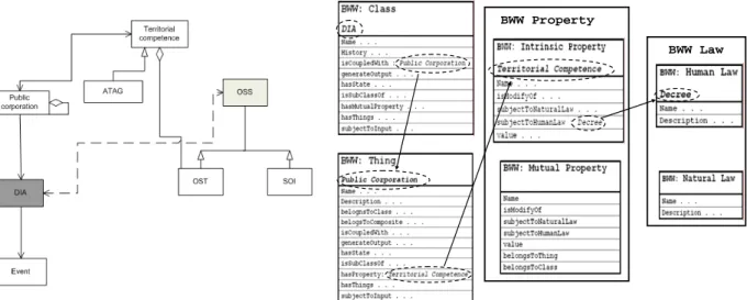
We explain here our experience of a research industrial project founded by the Italian Government about environmental monitoring. In this work, we adopt the UML-Like approach in order to obtain the domain specific conceptual model. The target is not a single application but a family of applications. After this phase, we adapt in an opportune way the BWW (Bunge-Wand-Weber) ontology to design the application domain and we evaluate which domain representation is more objective and useful for the following web information system design and development phases.
1. Introduction and background
Web application became in the last years complex application where several actor, several type of information, several technologies, several roles are involved. In order to link together these different key aspects it is very important to provide a methodological approach to helps in the design and later in the development of web application. We focus on methodologies that consider the information, navigation and transactional aspects typical of web application with several user on several devices. Very often when methodologies are applied they result strictly related to the designer experience about the domain knowledge. When the application domain is very large and several application (not only a single application) can be obtained from the design, it is important to formalize in some way the domain knowledge in order to not lies the application of the methodology only on the experience of the designer but in order to provide a common knowledge on which designer can work. In a few words it is important to take into account the conceptual design. We can see in Fig. 1 three different layers of analysis: the first, the domain layer, allows us to acquire the rigth knowledge of the entire application domain (named conceptual model); in the second, the web application layer, several design methodologies such as IDM, P-IDM and AWARE provide an engineeristic approach to the well-known web application paradigm (in order to solve the information and navigation open issues); and finally in the application layer, implementation details are taken into consideration.