Intel
®
Virtualization Technology
Specification for the Intel
®
Itanium
®
Architecture (VT-i)
Revision 2.0
April 2005
Notice: The Intel® Itanium® 2 processor may contain design defects or errors known as errata which may cause the product to deviate from published specifications. Current characterized errata are documented in this specification update.
THIS DOCUMENT AND RELATED MATERIALS AND INFORMATION ARE PROVIDED “AS IS” WITH NO WARRANTIES, EXPRESS OR IMPLIED, INCLUDING BUT NOT LIMITED TO ANY IMPLIED WARRANTY OF MERCHANTABILITY, FITNESS FOR A PARTICULAR PURPOSE, NON-INFRINGEMENT OF INTELLECTUAL PROPERTY RIGHTS, OR ANY WARRANTY OTHERWISE ARISING OUT OF ANY PROPOSAL, SPECIFICATION, OR SAMPLE. INTEL ASSUMES NO RESPONSIBILITY FOR ANY ERRORS CONTAINED IN THIS DOCUMENT AND HAS NO LIABILITIES OR OBLIGATIONS FOR ANY DAMAGES ARISING FROM OR IN CONNECTION WITH THE USE OF THIS DOCUMENT.
INFORMATION IN THIS DOCUMENT IS PROVIDED IN CONNECTION WITH INTEL® PRODUCTS. EXCEPT AS PROVIDED IN INTEL'S TERMS AND CONDITIONS OF SALE FOR SUCH PRODUCTS, INTEL ASSUMES NO LIABILITY WHATSOEVER, AND INTEL DISCLAIMS ANY EXPRESS OR IMPLIED WARRANTY RELATING TO SALE AND/OR USE OF INTEL PRODUCTS, INCLUDING LIABILITY OR WARRANTIES RELATING TO FITNESS FOR A PARTICULAR PURPOSE, MERCHANTABILITY, OR INFRINGEMENT OF ANY PATENT, COPYRIGHT, OR OTHER
INTELLECTUAL PROPERTY RIGHT.
Intel products are not intended for use in medical, life saving, life sustaining, critical control or safety systems, or in nuclear facility applications. Intel may make changes to specifications and product descriptions at any time, without notice.
Designers must not rely on the absence or characteristics of any features or instructions marked “reserved” or “undefined.” Intel reserves these for future definition and shall have no responsibility whatsoever for conflicts or incompatibilities arising from future changes to them.
Contact your local Intel sales office or your distributor to obtain the latest specifications and before placing your product order.
Copies of documents which have an ordering number and are referenced in this document, or other Intel literature may be obtained by calling 1-800-548-4725 or by visiting Intel's website at http://developer.intel.com/design/litcentr.
Intel and Itanium are trademarks or registered trademarks of Intel Corporation or its subsidiaries in the United States and other countries. Copyright © 2004-2005, Intel Corporation. All rights reserved.
Contents
1 Revision History ... 5
2 Introduction... 7
2.1 Affected Documents/Related Documents ... 7
2.2 Virtualization Terminology ... 7
2.3 Virtualization Concept ... 8
2.4 Virtualization Environment Overview... 9
2.5 Resource Virtualization Policies ... 9
3 Itanium® Architecture Changes... 11
4 Instruction Reference ... 19
5 Processor Abstraction Layer ... 53
5.1 Virtualization Terminology ... 53
5.2 PAL Virtualization Support ... 53
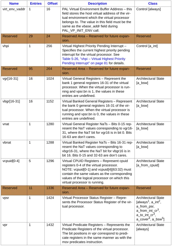
5.2.1 Virtual Processor Descriptor (VPD) ... 54
5.2.2 Interruption Handling in a Virtual Environment ... 58
5.2.3 PAL Intercepts in Virtual Environment... 60
5.2.4 Virtualization Optimizations ... 63
5.2.5 PAL Virtualization Services ... 72
5.3 PAL Procedure Summary... 74
5.4 PAL Virtualization Services Specification... 75
5.5 PAL Procedures for Virtualization ... 87
Figures
2-1 Virtual Processor Concept... 82-2 Interactions in a Virtualization Environment ... 9
2-3 Shared Virtualization Policy... 10
2-4 Dedicated Virtualization Policy ... 10
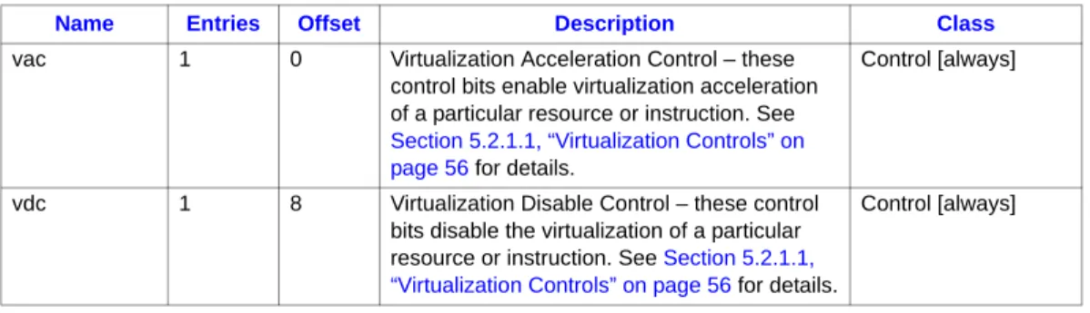
5-2 Virtualization Disable Control (vdc) ... 57
5-1 Virtualization Acceleration Control (vac) ... 57
5-3 PAL Virtualization Intercept Handoff Opcode (GR25) ... 63
Tables
4-1 Indirect Register File Mnemonics ... 305-1 Virtual Processor Descriptor (VPD)... 54
5-2 Virtualization Acceleration Control (vac) Fields... 57
5-3 Virtualization Disable Control (vdc) Fields... 57
5-4 IVA Settings after PAL Virtualization-Related Procedures and Services... 59
Read Optimization... 66
5-11 Interruptions When Interruption Control Register Read Optimization is Enabled ... 66
5-12 Synchronization Requirements for Interruption Control Register Write Optimization ... 66
5-13 Interruptions when Interruption Control Register Write Optimization is Enabled ... 67
5-14 Synchronization Requirements for MOV-from-PSR Optimization ... 67
5-15 Interruptions when MOV-from-PSR Optimization is Enabled... 67
5-16 Synchronization Requirements for MOV-from-CPUID Optimization ... 68
5-17 Interruptions when MOV-from-CPUID Optimization is Enabled ... 68
5-18 Synchronization Requirements for Cover Optimization ... 69
5-19 Interruptions when Cover Optimization is Enabled ... 69
5-20 Interruptions When Bank Switch Optimization is Enabled ... 69
5-21 Virtualization Disables Summary ... 69
5-22 PAL Virtualization Services ... 72
5-23 State Requirements for PSR for PAL Virtualization Services ... 73
5-24 PAL Virtualization Support Procedures ... 74
5-25 Virtual Processor Settings in Architectural Resources for PAL_VPS_RESUME_NORMAL and PAL_VPS_RESUME_HANDLER ... 76
5-26 vhpi – Virtual Highest Priority Pending Interrupt ... 81
5-27 vp_env_info – Virtual Environment Information Parameter... 90
5-28 config_options – Global Configuration Options ... 93
1
Revision History
Version Revision
Number Description Date
-002 2.0
• Added undefined behavior for RFI; modified the VMAL acceleration implementation; added description that d_extint will override a_int; Specified that CR.IVA is not preserved for some PAL Procedures.
April 2005
2
Introduction
This document describes the software interfaces for Itanium® architecture-based processors which support VT-i (Intel® Virtualization Technology for the Intel® Itanium® architecture). These additions allow for the virtualization of processor hardware in order to allow multiple instances of operating systems to be run on a single system. This document is intended for hardware system manufacturers and software developers of applications, operating systems, or tools.
Note: Intel Virtualization Technology is also supported on IA-32 Intel architecture processors. However the implementation of Intel Virtualization Technology for IA-32 architecture processors is different than VT-i due to many reasons, including the fundamental differences between the IA-32 and Itanium architectures. The IA-32 version of Intel Virtualization Technology is referred to as VT-x and documentation on VT-x can be found in the Intel Virtualization Technology
Specification for IA-32 Processors (VT-x).
2.1
Affected Documents/Related Documents
2.2
Virtualization Terminology
The following are terms related to Itanium architecture virtualization:
•
VT-i – Intel Virtualization Technology for the Itanium architecture.•
VT-x – Intel Virtualization Technology for the IA-32 architecture.•
Virtual Machine Monitor (VMM) – The VMM is the system software which implements software policies to manage/support virtualization of processor and platform resources.•
Virtual Processor Descriptor (VPD) – Represents the abstraction of the processor resources of a single virtual processor. The VPD consists of per-virtual-processor control information together with performance-critical architectural state. See Section 5.2.1, “Virtual Processor Descriptor (VPD)” on page 54 for details.•
Virtual Processor State – A memory data structure which represents the architectural state of a virtual processor. Part of the virtual processor state is located in the Virtual ProcessorTitle Document
Number
Intel® Itanium® Architecture Software Developer’s Manual, Volume 1: Application
Architecture 245317
Intel® Itanium® Architecture Software Developer’s Manual, Volume 2: System Architecture 245318
Intel® Itanium® Architecture Software Developer’s Manual, Volume 3: Instruction Set
Reference 245319
Intel® Itanium® Architecture Software Developer’s Manual, Specification Update 248699
•
PAL Intercepts – Interfaces where PAL transfers control to the VMM on virtualization events (execution of virtualized instructions/operations with PSR.vm==1). For details see Section 5.2.3, “PAL Intercepts in Virtual Environment” on page 60.2.3
Virtualization Concept
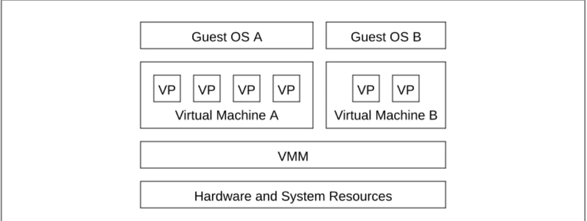
Modern operating system designs typically assume the operating system has complete and direct control of hardware and system resources. The operating system implements the policies to manage these resources to allow multiple user-level applications to be run. The goal of virtualization is to allow multiple instances of operating systems1 to be run on a system. In a typical virtualized environment, there will be a piece of system software responsible for virtualizing the hardware and system resources to allow multiple instances of the operating systems to be run. In the Itanium virtualization architecture, the term Virtual Machine Monitor or VMM refers to the software component that provides such functionality. The VMM is a piece of host software and is aware of the Itanium virtualization architecture.
For each instance of guest operating system, the VMM will need to create and present a virtual machine to the guest operating system. A virtual machine includes all the hardware and system resources (processors, memory, disk, network devices, and other peripherals) expected by the guest operating system. From the VMM perspective, these hardware and system resources are
“virtualized”. In the Itanium virtualization architecture, a virtual processor is a virtualized logical processor. The number of virtual processors created by a VMM in a virtual machine represents the number of logical processors presented to a guest operating system. For example, in Figure 2-1, Guest OS A will see a 4-way system, and Guest OS B will see a 2-way system. There will be at least one virtual processor in a virtual machine. Architecturally there is no limit on the number of virtual machines and virtual processors that can be created by the VMM2 on a system.
1. The operating systems can be same or different versions, and can come from different operating system vendors.
2. Although there is no architectural limit on the number of virtual machines and virtual processors on a system. There will be limits from the implementation of the hardware and system resources. In addition, there will also be limitations from VMM implementation (e.g., time to perform virtual processor switch).
Figure 2-1. Virtual Processor Concept
Hardware and System Resources VMM VP VP VP VP Virtual Machine A VP VP Virtual Machine B Guest OS A Guest OS B
2.4
Virtualization Environment Overview
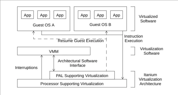
The term virtualization environment refers to the system environment created by the VMM to run virtualized software1. Figure 2-2 shows the main components in a virtualization environment2, and the interactions between them. A virtualization environment will include one or more
processors supporting virtualization, the PAL supporting virtualization, the virtual machine monitor, and virtualized software. The VMM is required to allocate the resources and create the virtualization environment before guest software can be launched. In a virtualization environment, virtualized software will continue to execute on the processor unmodified. Interruptions from the processor will be handled by the VMM. A new architecture interface is defined between the VMM and PAL for access to configuration and optimization options, virtualization services, and
virtualization intercept handling.
2.5
Resource Virtualization Policies
In a virtualization environment, guest operating systems are running virtualized. For each hardware and system resource on the system, there are typically two policies the VMM can choose to run the virtual processor(s) of the guest operating systems:
•
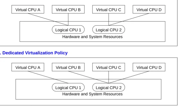
Shared Policy – With the shared policy, the actual hardware and system resources will be shared (time multiplexed) between multiple virtual processors. The VMM will need to implement the scheduling/switching/sharing mechanisms to support this policy. For example, in Figure 2-3, logical processor 1 is shared by two virtual processors, and logical processor 2 is shared by the other two virtual processors. In the Itanium virtualization architecture,virtualization accelerations are defined to optimize the usages of this policy. See
Section 6.2.4.1, “Virtualization Accelerations” on page 61 in Itanium Architecture Virtualization Specification Update, Rev 2.0 for details.
1. Note that the term virtual machine used in Section 2.3, “Virtualization Concept” on page 8 represents the set of virtual resources presented to a guest operating system. Typically the VMM will create one or more virtual machines in a virtualization environment. The usage model and
Figure 2-2. Interactions in a Virtualization Environment
Processor Supporting Virtualization VMM
Guest OS A Guest OS B
PAL Supporting Virtualization
App App App App App App
Instruction Execution
Interruptions
Architectural Software Interface
Resume Guest Execution
Itanium Virtualization Architecture Virtualization Software Virtualized Software
•
Dedicated Policy – With the dedicated policy, the actual hardware and system resources are dedicated to a particular virtual processor. There will be no sharing of that particular hardware and system resource between virtual processors. The virtual processor will have direct control of the particular hardware and system resource. For example, in Figure 2-4, logical processor 1 is dedicated to virtual processor A, and logical processor 2 is shared by multiple virtual processors. In the Itanium virtualization architecture, virtualization disables are defined to optimize the usages of this policy. See Section 6.2.4.2, “Virtualization Disables” on page 67 in Itanium Architecture Virtualization Specification Update, Rev 2.0 for details.The VMM decides the resource virtualization policies for the virtual processors at creation time, the policies are applicable until the virtual processor is terminated.
Since the resource virtualization policy is per-resource, the VMM can apply different policies for different resources on a virtual processor basis. For example, on a given virtual processor, the VMM can use a shared policy for an I/O device (i.e., the I/O device is shared between virtual processors), and can use a dedicated policy for the performance counters (i.e., the performance counters on the logical processor is not shared and can be controlled directly by the running virtual processor). In the Itanium virtualization architecture, since there are optimizations defined to support both policies for each resource1, the VMM cannot apply conflicting optimizations to these resources. The illegal settings are described in each acceleration and disable in Section 6.2.4.1, “Virtualization Accelerations” on page 61 in Itanium Architecture Virtualization Specification Update, Rev 2.0 and Section 6.2.4.2, “Virtualization Disables” on page 67 in Itanium Architecture Virtualization Specification Update, Rev 2.0.
1. For example, external interruption resources like external interrupt control registers, TPR and PSR.i.
Figure 2-3. Shared Virtualization Policy
Figure 2-4. Dedicated Virtualization Policy
Virtual CPU A Virtual CPU B Virtual CPU C Virtual CPU D
Hardware and System Resources Logical CPU 1 Logical CPU 2
Virtual CPU A Virtual CPU B Virtual CPU C Virtual CPU D
Hardware and System Resources Logical CPU 1 Logical CPU 2
3
Itanium
®
Architecture Changes
The rest of this document is formatted as a specification update to the Intel® Itanium® Architecture Software Developer’s Manual. This details out every change to the architecture for VT-i including the new instructions, processor behavior in the different virtualized modes, as well as the new PAL interfaces. The Itanium architecture is a living document and updates happen periodically. Future updates will be incorporated into the Intel® Itanium® Architecture Software Developer’s Manual and specification updates.
1.
Volume 2, Part I, Chapter 3 System State and Programming Model
1. New PSR.vm bit in Figure 3-2 Processor Status Register (PSR) (2:18):
2. New PSR.vm bit in Table 3-2 Processor Status Register Fields (2:19):
3. New section, Section 3.4, Processor Virtualization (2:35):
Itanium architecture processors may optionally implement a mechanism to support processor virtualization. This includes an additional PSR.vm bit (see Section 3.3.2, “Processor Status Register (PSR)”), which, when 1, causes certain instructions to take a virtualization fault (see Section 5.6, “Interruption Priorities” and “Virtualization Vector (0x6100)”).
The set of instructions which are virtualized by PSR.vm are listed in Table 3-10 below. 4. New Table 3-10, Virtualized Instructions (2:35):
31 30 29 28 27 26 25 24 23 22 21 20 19 18 17 16 15 14 13 12 11 10 9 8 7 6 5 4 3 2 1 0 rv rt tb lp db si di pp sp dfh dfl dt rv pk i ic rv mfh mfl ac up be rv 63 62 61 60 59 58 57 56 55 54 53 52 51 50 49 48 47 46 45 44 43 42 41 40 39 38 37 36 35 34 33 32 rv vm ia bn ed ri ss dd da id it mc is cpl system mask user mask
Field Bits Description Interruption
State
Serialization Required vm 46 Virtual Machine – When 1, an attempt to execute
certain instructions results in a virtualization fault. Implementation of this bit is optional. If the bit is not implemented, it is treated as a reserved bit. Written by the rfi and vmsw instructions.
0 rfi
Class Virtualized Instructions
All privileged instructions itc.i, itc.d, itr.i, itr.d, ptc.l, ptc.g, ptc.ga, ptc.e, ptr, tak, tpa, mov rr, mov pkr, mov cr, mov ibr, mov dbr, mov pmc, mov to pmd, ssm, rsm, mov psr, rfi, bsw
Some non-privileged instructions (virtualized at all privilege levels)
thash, ttag, mov from cpuid
Some non-privileged instructions (virtualized at privilege level 0)
5. New paragraph after Table 3-10 (2:35):
Processors which support processor virtualization must provide an implementation-dependent mechanism for disabling the vmsw instruction. When enabled, the vmsw instruction functions as described on the vmsw instruction page. When disabled, the vmsw instruction always raises a virtualization fault when executed at the most privileged level.
Processor virtualization is largely invisible to system software, and therefore its effects on virtualized instructions are not discussed in this document, except on the instruction description pages themselves.
2.
Volume 2, Part I, Chapter 4, Addressing and Protection
1. Section 4.3.2, Unimplemented Virtual Address Bits, add the following paragraph before the final paragraph in the section (2:62):
If the PSR.vm bit is implemented, and if PSR.vm is 1, then virtual addresses are treated as though one additional virtual address bit were unimplemented. If the PSR.vm bit is implemented, at least 52 virtual address bits must be implemented.
2. Section 4.3.3, Instruction Behavior with Unimplemented Addresses, add the following bullet after the last bullet (2:63):
•
The behavior of executing vmsw.1 in a bundle whose address will become unimplemented after PSR.vm is set to 1 is undefined.3.
Volume 2, Part I, Chapter 5, Interruptions
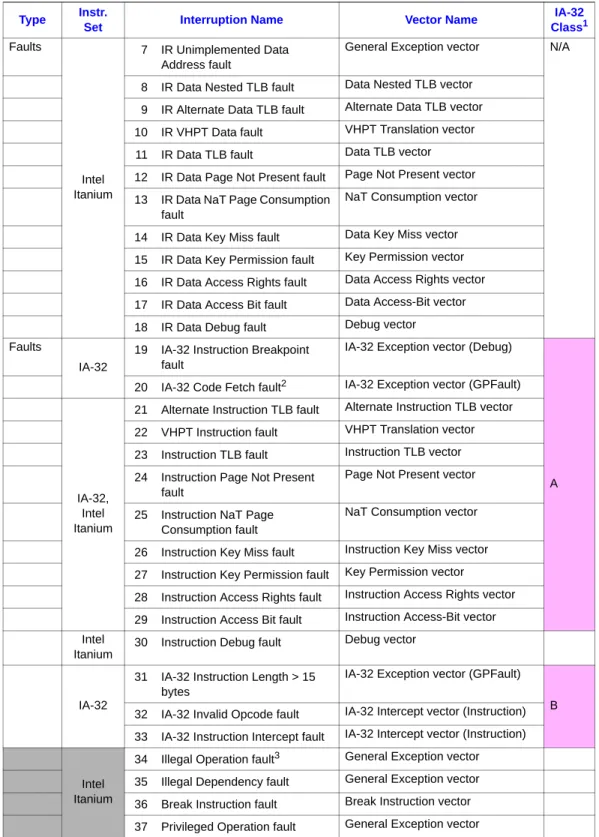
1. Add Virtualization fault and Virtual External Interrupt in Table 5-6, Interruption Priorities (2:92):
Reading AR[ITC] with PSR.si==1 takes (virtualized at all privilege levels)
mov from ar.itc
Instructions which write privileged registers
mov to itc
Class Virtualized Instructions
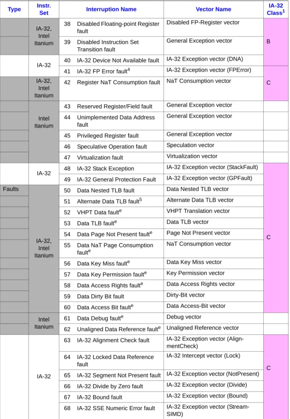
Table 5-6 Interruption Priorities (Sheet 1 of 4) Type Instr.
Set Interruption Name Vector Name
IA-32 Class1 Aborts IA-32, Intel® Itanium®
1 Machine Reset (RESET) PALE_RESET vector
N/A 2 Machine Check (MCA) PALE_CHECK vector
Inter-rupts
3 Initialization Interrupt (INIT) PALE_INIT vector
N/A 4 Platform Management Interrupt
(PMI)
PALE_PMI vector
5 External Interrupt (INT) External Interrupt vector
Faults
Intel Itanium
7 IR Unimplemented Data Address fault
General Exception vector N/A
8 IR Data Nested TLB fault Data Nested TLB vector 9 IR Alternate Data TLB fault Alternate Data TLB vector 10 IR VHPT Data fault VHPT Translation vector 11 IR Data TLB fault Data TLB vector 12 IR Data Page Not Present fault Page Not Present vector 13 IR Data NaT Page Consumption
fault
NaT Consumption vector
14 IR Data Key Miss fault Data Key Miss vector 15 IR Data Key Permission fault Key Permission vector 16 IR Data Access Rights fault Data Access Rights vector 17 IR Data Access Bit fault Data Access-Bit vector 18 IR Data Debug fault Debug vector Faults
IA-32
19 IA-32 Instruction Breakpoint fault
IA-32 Exception vector (Debug)
A 20 IA-32 Code Fetch fault2 IA-32 Exception vector (GPFault)
IA-32, Intel Itanium
21 Alternate Instruction TLB fault Alternate Instruction TLB vector 22 VHPT Instruction fault VHPT Translation vector 23 Instruction TLB fault Instruction TLB vector 24 Instruction Page Not Present
fault
Page Not Present vector
25 Instruction NaT Page Consumption fault
NaT Consumption vector
26 Instruction Key Miss fault Instruction Key Miss vector 27 Instruction Key Permission fault Key Permission vector
28 Instruction Access Rights fault Instruction Access Rights vector 29 Instruction Access Bit fault Instruction Access-Bit vector Intel
Itanium
30 Instruction Debug fault Debug vector
IA-32
31 IA-32 Instruction Length > 15 bytes
IA-32 Exception vector (GPFault) B 32 IA-32 Invalid Opcode fault IA-32 Intercept vector (Instruction) 33 IA-32 Instruction Intercept fault IA-32 Intercept vector (Instruction)
Intel Itanium
34 Illegal Operation fault3 General Exception vector 35 Illegal Dependency fault General Exception vector 36 Break Instruction fault Break Instruction vector 37 Privileged Operation fault General Exception vector Table 5-6 Interruption Priorities (Sheet 2 of 4)
Type Instr.
Set Interruption Name Vector Name
IA-32 Class1
IA-32, Intel Itanium
38 Disabled Floating-point Register fault
Disabled FP-Register vector
B 39 Disabled Instruction Set
Transition fault
General Exception vector
IA-32 40 IA-32 Device Not Available fault
IA-32 Exception vector (DNA) 41 IA-32 FP Error fault4 IA-32 Exception vector (FPError)
C IA-32,
Intel Itanium
42 Register NaT Consumption fault NaT Consumption vector
Intel Itanium
43 Reserved Register/Field fault General Exception vector 44 Unimplemented Data Address
fault
General Exception vector
45 Privileged Register fault General Exception vector 46 Speculative Operation fault Speculation vector 47 Virtualization fault Virtualization vector IA-32 48 IA-32 Stack Exception
IA-32 Exception vector (StackFault)
C 49 IA-32 General Protection Fault IA-32 Exception vector (GPFault) Faults
IA-32, Intel Itanium
50 Data Nested TLB fault Data Nested TLB vector 51 Alternate Data TLB fault5 Alternate Data TLB vector 52 VHPT Data faulte VHPT Translation vector 53 Data TLB faulte Data TLB vector 54 Data Page Not Present faulte Page Not Present vector 55 Data NaT Page Consumption
faulte
NaT Consumption vector
56 Data Key Miss faulte Data Key Miss vector 57 Data Key Permission faulte Key Permission vector 58 Data Access Rights faulte Data Access Rights vector 59 Data Dirty Bit fault Dirty-Bit vector
60 Data Access Bit faulte Data Access-Bit vector Intel
Itanium
61 Data Debug faulte Debug vector
62 Unaligned Data Reference faulte Unaligned Reference vector
IA-32
63 IA-32 Alignment Check fault IA-32 Exception vector (Align-mentCheck)
C 64 IA-32 Locked Data Reference
fault
IA-32 Intercept vector (Lock)
65 IA-32 Segment Not Present fault IA-32 Exception vector (NotPresent) 66 IA-32 Divide by Zero fault IA-32 Exception vector (Divide) 67 IA-32 Bound fault IA-32 Exception vector (Bound) 68 IA-32 SSE Numeric Error fault IA-32 Exception vector
(Stream-SIMD) Table 5-6 Interruption Priorities (Sheet 3 of 4)
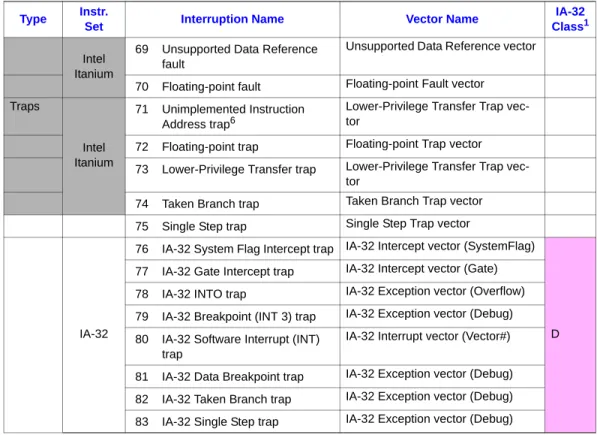
Type Instr.
Set Interruption Name Vector Name
IA-32 Class1
2. Add Virtual External Interrupt vector and virtualization vector in Table 5-7, Interruption Vector Table (IVT) (2:96):
4.
Volume 2, Part I, Chapter 8, Interruption Vector Descriptions
1. Add Virtual External Interrupt vector and virtualization vector in Table 8-1, Writing of Interruption Resources by Vector (2:146):
Intel Itanium
69 Unsupported Data Reference fault
Unsupported Data Reference vector
70 Floating-point fault Floating-point Fault vector Traps
Intel Itanium
71 Unimplemented Instruction Address trap6
Lower-Privilege Transfer Trap vec-tor
72 Floating-point trap Floating-point Trap vector 73 Lower-Privilege Transfer trap Lower-Privilege Transfer Trap
vec-tor
74 Taken Branch trap Taken Branch Trap vector 75 Single Step trap Single Step Trap vector
IA-32
76 IA-32 System Flag Intercept trap IA-32 Intercept vector (SystemFlag)
D 77 IA-32 Gate Intercept trap IA-32 Intercept vector (Gate)
78 IA-32 INTO trap IA-32 Exception vector (Overflow) 79 IA-32 Breakpoint (INT 3) trap IA-32 Exception vector (Debug) 80 IA-32 Software Interrupt (INT)
trap
IA-32 Interrupt vector (Vector#)
81 IA-32 Data Breakpoint trap IA-32 Exception vector (Debug) 82 IA-32 Taken Branch trap IA-32 Exception vector (Debug) 83 IA-32 Single Step trap IA-32 Exception vector (Debug) NOTES:
1. IA-32 Interruption Class, see Section 5.6.1, “IA-32 Interruption Priorities and Classes” on page 2:105 for details.
2. IA-32 Code Fetch faults include Code Segment Limit Violation and other Code Fetch checks defined in
Section 6.2.3.3, “IA-32 Environment Runtime Integrity Checks” on page 121.
3. Illegal Operation faults can be taken for certain predicated off reserved opcodes. For details, refer to Section 4.1, “Format Summary” on page 272.
4. IA-32 FP Error fault conditions detected on an IA-32 FP instruction are reported as a fault on the next IA-32 FP instruction that performs an FWAIT operation.
5. If not deferred.
6. Unimplemented Instruction Address traps on emulated check instructions have a lower priority than Taken Branch trap and Single Step trap. See “Speculation vector (0x5700)” on page 193.
Table 5-6 Interruption Priorities (Sheet 4 of 4) Type Instr.
Set Interruption Name Vector Name
IA-32 Class1
Offset Vector Name Interruption(s) Page
0x3400 Virtual External Interrupt vector 6 2:183
0x6100 Virtualization vector 47 2:202
Interruption Resource IIP, IPSR,
IIPA, IFS.v IFA ITIR IHA IIM ISR
PSR.ic at time of interruption 0 1 0 1 0 1 0 1 0 1 0 1 Interruption Vector
2. Add Virtual External Interrupt vector and Virtualization vector in Table 8-2, ISR Values on Interruption (2:147):
3. Add Virtual External Interrupt vector (0x3400) and Virtualization vector (0x6100) (2:186):
Vector / Interruption ed ei1
NOTES:
1. ISR.ei is equal to IPSR.ri for all faults and external interrupts (1 for faults and interrupts on the L+X instruction of an MLX). For traps, ISR.ei points at the excepting instruction (2 for traps on the L+X instruction of an MLX).
so ni2
2. If ISR.ni is 1, the interruption occurred either when PSR.ic was 0 or was in-flight. ir3
3. ISR.ri captures the value of RSE.CFLE at the time of an interruption. rs4
4. ISR.rs is 1 for interruptions caused by mandatory RSE fills/spills and 0 for all others. sp5
5. ISR.sp is 1 for interruptions caused by speculative loads and zero for all others. na6
6. ISR.na is 1 for interruptions caused by non-access instructions and zero for all others.
r w x
Virtual External Interrupt Vector
Virtual External Interrupt 0 ri 0 ni ir7
7. ISR.ir is 1 if an external interrupt was taken when mandatory RSE fills caused by a br.ret or rfi were re-loading the current register stack frame.
0 0 0 0 0 0
Virtualization Vector
Name Virtual External Interrupt Vector (0x3400)
Cause The guest highest pending interrupt (VHPI) specified by the VMM is unmasked on the virtual processor.
IPSR.is indicates which instruction set was executing at the time of the interruption.
Interruptions on this vector: Virtual External interrupt
Parameters IIP, IPSR, IIPA, IFS – are defined; refer to page 2:163 for a detailed description. ISR – The ISR.ei bits are set to indicate which instruction was to be executed when the external interrupt event was taken. The defined ISR bits are specified below. For external interrupts taken in the IA-32 instruction set, ISR.ei, ni and ir bits are 0.
Notes: Software is expected to avoid situations which could cause ISR.ni to be 1. 31 30 29 28 27 26 25 24 23 22 21 20 19 18 17 16 15 14 13 12 11 10 9 8 7 6 5 4 3 2 1 0
0 0 0
63 62 61 60 59 58 57 56 55 54 53 52 51 50 49 48 47 46 45 44 43 42 41 40 39 38 37 36 35 34 33 32
Name Virtualization Vector (0x6100)
Cause An attempt is made to execute an instruction which requires virtualization. This fault cannot be raised by IA-32 instructions.
Interruptions on this vector: Virtualization fault
Parameters IIP, IPSR, IIPA, IFS – are defined; refer to page 2:163 for a detailed description. ISR – The ISR.ei bits are set to indicate which instruction caused the exception. The defined ISR bits are specified below.
5.
Volume 2, Part I, Chapter 11, Processor Abstraction Layer
1. Add PSR.vm bit in Table 11-19, State Requirements for PSR (2:289):
2. Add a table footnote after “preserved” in the IVA field of Table 11-21, System Register Conventions:
“On some implementations, PAL virtualization support procedures may program IVA to a different value. Refer to the description of the PAL virtualization procedures for details. 3. Add bits 40 and 54 in Table 11-54, Processor Features (2:360):
6.
Volume 3, Chapter 2, Instruction Reference
See “Instruction Reference” on page 16 for changes related to the virtualized instructions.
7.
Revised Chapter 11 of Volume 2, Processor Abstraction Layer (text
included at end of this update)
Volume 2, Chapter 11, Processor Abstraction Layer has been modified to include new content to support processor virtualization. The new content from Chapter 11 is presented at the end of this update for convenience.
31 30 29 28 27 26 25 24 23 22 21 20 19 18 17 16 15 14 13 12 11 10 9 8 7 6 5 4 3 2 1 0
0 0 0 0
63 62 61 60 59 58 57 56 55 54 53 52 51 50 49 48 47 46 45 44 43 42 41 40 39 38 37 36 35 34 33 32
0 0 ei 0 ni 0 0 0 0 0 0 0
PSR Bit Description Entry Exit Class
vm processor virtualization 0 0 unchanged
Bit Class Control Description
40 Opt. No Virtual Machine features implemented. Denotes whether PSR.vm is implemented. This feature may only be interrogated by PAL_PROC_GET_FEATURES. It may not be enabled or disabled by PAL_PROC_SET_FEATURES. The corresponding argument is ignored.
54 Opt. Req. Enable the use of the VMSW instruction. When 0, the vmsw instruction causes a virtualization fault when executed at the most privileged level. When 1, this bit will enable normal operation of the vmsw instruction.
4
Instruction Reference
bsw — Bank Switch
Format: bsw.0 zero_form B8
bsw.1 one_form B8
Description: This instruction switches to the specified register bank. The zero_form specifies Bank 0 for GR16 to GR31. The one_form specifies Bank 1 for GR16 to GR31. After the bank switch the previous register bank is no longer accessible but does retain its current state. If the new and old register banks are the same, bsw is effectively a nop, although there may be a performance degradation.
Abswinstruction must be the last instruction in an instruction group; otherwise, operation is undefined. Instructions in the same instruction group that access GR16 to GR31 reference the previous register bank. Subsequent instruction groups reference the new register bank.
This instruction can only be executed at the most privileged level, and when PSR.vm is 0.
This instruction cannot be predicated. Operation: if (!followed_by_stop()) undefined_behavior(); if (PSR.cpl != 0) privileged_operation_fault(0); if (PSR.vm == 1) virtualization_fault(); if (zero_form) PSR.bn = 0; else // one_form PSR.bn = 1;
Interruptions: Privileged Operation fault Virtualization fault
Serialization: This instruction does not require any additional instruction or data serialization operation. The bank switch occurs synchronously with its execution.
cover — Cover Stack Frame
Format: cover B8
Description: A new stack frame of zero size is allocated which does not include any registers from the previous frame (as though all output registers in the previous frame had been locals). The register rename base registers are reset. If interruption collection is disabled (PSR.ic is zero), then the old value of the Current Frame Marker (CFM) is copied to the Interruption Function State register (IFS), and IFS.v is set to one. Acoverinstruction must be the last instruction in an instruction group; otherwise, operation is undefined.
If PSR.cpl is non-zero, this instruction can only be executed when PSR.vm is also 0. This instruction cannot be predicated.
Operation: if (!followed_by_stop()) undefined_behavior(); if (PSR.cpl == 0 && PSR.vm == 1) virtualization_fault(); alat_frame_update(CFM.sof, 0); rse_preserve_frame(CFM.sof); if (PSR.ic == 0) { CR[IFS].ifm = CFM; CR[IFS].v = 1; } CFM.sof = 0; CFM.sol = 0; CFM.sor = 0; CFM.rrb.gr = 0; CFM.rrb.fr = 0; CFM.rrb.pr = 0;
itc — Insert Translation Cache
Format: (qp) itc.i r2 instruction_form M41
(qp) itc.d r2 data_form M41
Description: An entry is inserted into the instruction or data translation cache. GR r2 specifies the physical address portion of the translation. ITIR specifies the protection key, page size and additional information. The virtual address is specified by the IFA register and the region register is selected by IFA{63:61}. The processor determines which entry to replace based on an implementation-specific replacement algorithm.
The visibility of the itc instruction to externally generated purges (ptc.g, ptc.ga) must occur before subsequent memory operations. From a software perspective, this is similar to acquire semantics. Serialization is still required to observe the side-effects of a translation being present.
itc must be the last instruction in an instruction group; otherwise, its behavior (including its ordering semantics) is undefined.
The TLB is first purged of any overlapping entries as specified by Table 4-1 on page 49.
This instruction can only be executed at the most privileged level, and when PSR.ic and PSR.vm are both 0.
To ensure forward progress, software must ensure that PSR.ic remains 0 until rfi-ing to the instruction that requires the translation.
Operation: if (PR[qp]) { if (!followed_by_stop()) undefined_behavior(); if (PSR.ic) illegal_operation_fault(); if (PSR.cpl != 0) privileged_operation_fault(0); if (GR[r2].nat) register_nat_consumption_fault(0); tmp_size = CR[ITIR].ps; tmp_va = CR[IFA]{60:0}; tmp_rid = RR[CR[IFA]{63:61}].rid;
tmp_va = align_to_size_boundary(tmp_va, tmp_size); if (is_reserved_field(TLB_TYPE, GR[r2], CR[ITIR])) reserved_register_field_fault(); if (!impl_check_mov_ifa() && unimplemented_virtual_address(CR[IFA], PSR.vm)) unimplemented_data_address_fault(0); if (PSR.vm == 1) virtualization_fault(); if (instruction_form) {
tlb_must_purge_itc_entries(tmp_rid, tmp_va, tmp_size); tlb_may_purge_dtc_entries(tmp_rid, tmp_va, tmp_size); slot = tlb_replacement_algorithm(ITC_TYPE);
tlb_insert_inst(slot, GR[r2], CR[ITIR], CR[IFA], tmp_rid,
TC);
} else { // data_form
tlb_may_purge_itc_entries(tmp_rid, tmp_va, tmp_size); slot = tlb_replacement_algorithm(DTC_TYPE);
tlb_insert_data(slot, GR[r2], CR[ITIR], CR[IFA], tmp_rid, TC);
} }
Interruptions: Machine Check abort Reserved Register/Field fault
Illegal Operation fault Unimplemented Data Address
fault
Privileged Operation fault Virtualization fault Register NaT Consumption fault
Serialization: For the instruction_form, software must issue an instruction serialization operation before a dependent instruction fetch access. For the data_form, software must issue a data serialization operation before issuing a data access or non-access reference dependent on the new translation.
itr — Insert Translation Register
Format: (qp) itr.i itr[r3] = r2 instruction_form M42
(qp) itr.d dtr[r3] = r2 data_form M42
Description: A translation is inserted into the instruction or data translation register specified by the contents of GR r3. GR r2 specifies the physical address portion of the
translation. ITIR specifies the protection key, page size and additional information. The virtual address is specified by the IFA register and the region register is selected by IFA{63:61}.
As described in Table 4-1, “Purge Behavior of TLB Instructions” on page 49, the TLB is first purged of any entries that overlap with the newly inserted translation. The translation previously contained in the TR slot specified by GR r3 is not necessarily purged from the processor's TLBs and may remain as a TC entry. To ensure that the previous TR translation is purged, software must use explicit ptr instructions before inserting the new TR entry.
This instruction can only be executed at the most privileged level, and when PSR.ic and PSR.vm are both 0.
Operation: if (PR[qp]) { if (PSR.ic) illegal_operation_fault(); if (PSR.cpl != 0) privileged_operation_fault(0); if (GR[r3].nat || GR[r2].nat) register_nat_consumption_fault(0); slot = GR[r3]{7:0}; tmp_size = CR[ITIR].ps; tmp_va = CR[IFA]{60:0}; tmp_rid = RR[CR[IFA]{63:61}].rid;
tmp_va = align_to_size_boundary(tmp_va, tmp_size); tmp_tr_type = instruction_form ? ITR_TYPE : DTR_TYPE; if (is_reserved_reg(tmp_tr_type, slot)) reserved_register_field_fault(); if (is_reserved_field(TLB_TYPE, GR[r2], CR[ITIR])) reserved_register_field_fault(); if (!impl_check_mov_ifa() && unimplemented_virtual_address(CR[IFA], PSR.vm)) unimplemented_data_address_fault(0); if (PSR.vm == 1) virtualization_fault(); if (instruction_form) {
tlb_must_purge_itc_entries(tmp_rid, tmp_va, tmp_size); tlb_may_purge_dtc_entries(tmp_rid, tmp_va, tmp_size); tlb_insert_inst(slot, GR[r2], CR[ITIR], CR[IFA], tmp_rid, TR);
} else { // data_form
tlb_must_purge_dtc_entries(tmp_rid, tmp_va, tmp_size); tlb_may_purge_itc_entries(tmp_rid, tmp_va, tmp_size); tlb_insert_data(slot, GR[r2], CR[ITIR], CR[IFA], tmp_rid,
TR); } }
Interruptions: Machine Check abort Reserved Register/Field fault
Illegal Operation fault Unimplemented Data Address
fault
Privileged Operation fault Virtualization fault Register NaT Consumption fault
mov — Move Application Register
Format: (qp) mov r1 = ar3 pseudo-op (qp) mov ar3 = r2 pseudo-op (qp) mov ar3 = imm8 pseudo-op
(qp) mov.i r1 = ar3 i_form, from_form I28
(qp) mov.i ar3 = r2 i_form, register_form, to_form I26
(qp) mov.i ar3 = imm8 i_form, immediate_form, to_form I27
(qp) mov.m r1 = ar3 m_form, from_form M31
(qp) mov.m ar3 = r2 m_form, register_form, to_form M29
(qp) mov.m ar3 = imm8 m_form, immediate_form, to_form M30
Description: The source operand is copied to the destination register.
In the from_form, the application register specified by ar3 is copied into GR r1 and the corresponding NaT bit is cleared.
In the to_form, the value in GR r2 (in the register_form), or the sign-extended value in imm8 (in the immediate_form), is placed in AR ar3. In the register_form if the NaT bit corresponding to GR r2 is set, then a Register NaT Consumption fault is raised.
Only a subset of the application registers can be accessed by each execution unit (M or I). Table 3-3 on page 28 indicates which application registers may be accessed from which execution unit type. An access to an application register from the wrong unit type causes an Illegal Operation fault.
This instruction has multiple forms with the pseudo operation eliminating the need for specifying the execution unit. Accesses of the ARs are always implicitly serialized. While implicitly serialized, read-after-write and write-after-write dependency violations must be avoided (e.g., setting CCV, followed by cmpxchg in the same instruction group, or simultaneous writes to the UNAT register by ld.fill and mov to UNAT).
Instruction Reference
Operation: if (PR[qp]) {
tmp_type = (i_form ? AR_I_TYPE : AR_M_TYPE); if (is_reserved_reg(tmp_type, ar3))
illegal_operation_fault(); if (from_form) {
check_target_register(r1);
if (((ar3 == BSPSTORE) || (ar3 == RNAT)) && (AR[RSC].mode
!= 0))
illegal_operation_fault();
if (ar3 == ITC && PSR.si && PSR.cpl != 0)
privileged_register_fault();
if (ar3 == ITC && PSR.si && PSR.vm == 1)
virtualization_fault();
GR[r1] = (is_ignored_reg(ar3)) ? 0 : AR[ar3];
GR[r1].nat = 0;
} else { // to_form tmp_val = (register_form) ? GR[r2] : sign_ext(imm8, 8);
if (is_read_only_register(AR_TYPE, ar3) ||
(((ar3 == BSPSTORE) || (ar3 == RNAT)) && (AR[RSC].mode
!= 0)))
illegal_operation_fault(); if (register_form && GR[r2].nat)
register_nat_consumption_fault(0);
if (is_reserved_field(AR_TYPE, ar3, tmp_val)) reserved_register_field_fault();
if ((is_kernel_reg(ar3) || ar3 == ITC) && (PSR.cpl != 0)) privileged_register_fault();
if (ar3 == ITC && PSR.vm == 1) virtualization_fault(); if (!is_ignored_reg(ar3)) {
tmp_val = ignored_field_mask(AR_TYPE, ar3, tmp_val);
// check for illegal promotion
if (ar3 == RSC && tmp_val{3:2} u< PSR.cpl) tmp_val{3:2} = PSR.cpl; AR[ar3] = tmp_val; if (ar3 == BSPSTORE) { AR[BSP] = rse_update_internal_stack_pointers(tmp_val); AR[RNAT] = undefined(); } } } }
Interruptions: Illegal Operation fault Privileged Register fault Register NaT Consumption fault Virtualization fault Reserved Register/Field fault
mov — Move Control Register
Format: (qp) mov r1 = cr3 from_form M33
(qp) mov cr3 = r2 to_form M32
Description: The source operand is copied to the destination register.
For the from_form, the control register specified by cr3 is read and the value copied into GR r1.
For the to_form, GR r2 is read and the value copied into CR cr3.
Control registers can only be accessed at the most privileged level, and when PSR.vm is 0. Reading or writing an interruption control register (CR16-CR25), when the PSR.ic bit is one, will result in an Illegal Operation fault.
Operation: if (PR[qp]) {
if (is_reserved_reg(CR_TYPE, cr3)
|| to_form && is_read_only_reg(CR_TYPE, cr3)
|| PSR.ic && is_interruption_cr(cr3)) { illegal_operation_fault(); } if (from_form) check_target_register(r1); if (PSR.cpl != 0) privileged_operation_fault(0); if (from_form) { if (PSR.vm == 1) virtualization_fault(); if (cr3 == IVR) check_interrupt_request(); if (cr3 == ITIR) GR[r1] = impl_itir_cwi_mask(CR[ITIR]); else GR[r1] = CR[cr3]; GR[r1].nat = 0; } else { // to_form if (GR[r2].nat) register_nat_consumption_fault(0); if (is_reserved_field(CR_TYPE, cr3, GR[r2])) reserved_register_field_fault();
if ((cr3 == IFA) && impl_check_mov_ifa() &&
unimplemented_virtual_address(GR[r2], PSR.vm)) unimplemented_data_address_fault(0); if (PSR.vm == 1) virtualization_fault(); if (cr3 == EOI) end_of_interrupt(); tmp_val = ignored_field_mask(CR_TYPE, cr3, GR[r2]); CR[cr3] = tmp_val; if (cr3 == IIPA) last_IP = tmp_val; } }
Instruction Reference
Interruptions: Illegal Operation fault Reserved Register/Field fault Privileged Operation fault Virtualization fault
Register NaT Consumption fault
Serialization: Reads of control registers reflect the results of all prior instruction groups and interruptions.
In general, writes to control registers do not immediately affect subsequent instructions. Software must issue a serialize operation before a dependent instruction uses a modified resource.
Control register writes are not implicitly synchronized with a corresponding control register read and requires data serialization.
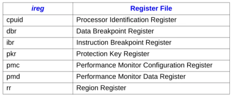
mov — Move Indirect Register
Format: (qp) mov r1 = ireg[r3] from_form M43
(qp) mov ireg[r3] = r2 to_form M42
Description: The source operand is copied to the destination register.
For move from indirect register, GR r3 is read and the value used as an index into the register file specified by ireg (see Table 4-1). The indexed register is read and its value is copied into GR r1.
For move to indirect register, GR r3 is read and the value used as an index into the register file specified by ireg. GR r2 is read and its value copied into the indexed register.
For all register files other than the region registers, bits {7:0} of GR r3 are used as the index. For region registers, bits {63:61} are used. The remainder of the bits are ignored.
Instruction and data breakpoint, performance monitor configuration, protection key, and region registers can only be accessed at the most privileged level. Performance monitor data registers can only be written at the most privileged level. The CPU identification registers can only be read. There is no to_form of this instruction.
For move to protection key register, the processor ensures uniqueness of protection keys by checking new valid protection keys against all protection key registers. If any matching keys are found, duplicate protection keys are invalidated.
Apart from the PMC and PMD register files, access of a non-existent register results in a Reserved Register/Field fault. All accesses to the implementation-dependent portion of PMC and PMD register files result in implementation dependent behavior but do not fault.
Modifying a region register or a protection key register which is being used to translate:
• The executing instruction stream when PSR.it == 1, or • The data space for an eager RSE reference when PSR.rt == 1 is an undefined operation.
Table 4-1. Indirect Register File Mnemonics
ireg Register File
cpuid Processor Identification Register dbr Data Breakpoint Register ibr Instruction Breakpoint Register pkr Protection Key Register
pmc Performance Monitor Configuration Register pmd Performance Monitor Data Register
Instruction Reference
Operation: if (PR[qp]) {
if (ireg == RR_TYPE)
tmp_index = GR[r3]{63:61}; else // all other register types
tmp_index = GR[r3]{7:0};
if (from_form) {
check_target_register(r1);
if (PSR.cpl != 0 && !(ireg == PMD_TYPE || ireg == CPUID_TYPE))
privileged_operation_fault(0); if (GR[r3].nat)
register_nat_consumption_fault(0); if (is_reserved_reg(ireg, tmp_index))
reserved_register_field_fault(); if (PSR.vm == 1 && ireg != PMD_TYPE)
virtualization_fault(); if (ireg == PMD_TYPE) {
if ((PSR.cpl != 0) && ((PSR.sp == 1) || (tmp_index > 3 &&
tmp_index <= IMPL_MAXGENERIC_PMCPMD && PMC[tmp_index].pm == 1))) GR[r1] = 0; else GR[r1] = pmd_read(tmp_index); } else switch (ireg) {
case CPUID_TYPE: GR[r1] = CPUID[tmp_index]; break;
case DBR_TYPE: GR[r1] = DBR[tmp_index]; break; case IBR_TYPE: GR[r1] = IBR[tmp_index]; break; case PKR_TYPE: GR[r1] = PKR[tmp_index]; break; case PMC_TYPE: GR[r1] = pmc_read(tmp_index); break;
case RR_TYPE: GR[r1] = RR[tmp_index]; break; } GR[r1].nat = 0; } else { // to_form if (PSR.cpl != 0) privileged_operation_fault(0); if (GR[r2].nat || GR[r3].nat) register_nat_consumption_fault(0); if (is_reserved_reg(ireg, tmp_index)
|| is_reserved_field(ireg, tmp_index, GR[r2]))
reserved_register_field_fault(); if (PSR.vm == 1)
virtualization_fault();
if (ireg == PKR_TYPE && GR[r2]{0} == 1) { // writing
valid prot key
if ((tmp_slot = tlb_search_pkr(GR[r2]{31:8})) !=
NOT_FOUND)
switch (ireg) {
case DBR_TYPE: DBR[tmp_index] = tmp_val; break; case IBR_TYPE: IBR[tmp_index] = tmp_val; break; case PKR_TYPE: PKR[tmp_index] = tmp_val; break; case PMC_TYPE: pmc_write(tmp_index, tmp_val); break;
case PMD_TYPE: pmd_write(tmp_index, tmp_val); break;
case RR_TYPE: RR[tmp_index]= tmp_val; break; }
} }
Interruptions: Illegal Operation fault Reserved Register/Field fault Privileged Operation fault Virtualization fault
Register NaT Consumption fault
Serialization: For move to data breakpoint registers, software must issue a data serialize operation before issuing a memory reference dependent on the modified register. For move to instruction breakpoint registers, software must issue an instruction serialize operation before fetching an instruction dependent on the modified register.
For move to protection key, region, performance monitor configuration, and performance monitor data registers, software must issue an instruction or data serialize operation to ensure the changes are observed before issuing any dependent instruction.
To obtain improved accuracy, software can issue an instruction or data serialize operation before reading the performance monitors.
Instruction Reference
mov — Move Processor Status Register
Format: (qp) mov r1 = psr from_form M36
(qp) mov psr.l = r2 to_form M35
Description: The source operand is copied to the destination register. See Section 3.3.2, “Processor Status Register (PSR)” on page 22.
For move from processor status register, PSR bits {36:35} and {31:0} are read, and copied into GR r1. All other bits of the PSR read as zero.
For move to processor status register, GR r2 is read, bits {31:0} copied into PSR{31:0} and bits {45:32} are ignored. All bits of GR r2 corresponding to reserved fields of the PSR must be 0 or a Reserved Register/Field fault will result. Moves to and from the PSR can only be performed at the most privileged level, and when PSR.vm is 0.
The contents of the interruption resources (that are overwritten when the PSR.ic bit is 1) are undefined if an interruption occurs between the enabling of the PSR.ic bit and a subsequent instruction serialize operation.
Operation: if (PR[qp]) { if (from_form) check_target_register(r1); if (PSR.cpl != 0) privileged_operation_fault(0); if (from_form) { if (PSR.vm == 1) virtualization_fault();
tmp_val = zero_ext(PSR{31:0}, 32); // read lower 32 bits
tmp_val |= PSR{36:35} << 35; // read mc and it bits
GR[r1] = tmp_val; // other bits read as zero GR[r1].nat = 0; } else { // to_form if (GR[r2].nat) register_nat_consumption_fault(0); if (is_reserved_field(PSR_TYPE, PSR_MOVPART, GR[r2])) reserved_register_field_fault(); if (PSR.vm == 1) virtualization_fault(); PSR{31:0} = GR[r2]{31:0}; } }
Interruptions: Illegal Operation fault Reserved Register/Field fault Privileged Operation fault Virtualization fault
Register NaT Consumption fault
Serialization: Software must issue an instruction or data serialize operation before issuing instructions dependent upon the altered PSR bits. Unlike with the rsm instruction,
ptc.e — Purge Translation Cache Entry
Format: (qp) ptc.e r3 M47
Description: One or more translation entries are purged from the local processor’s instruction and data translation cache. Translation Registers and the VHPT are not modified. The number of translation cache entries purged is implementation specific. Some implementations may purge all levels of the translation cache hierarchy with one iteration of PTC.e, while other implementations may require several iterations to flush all levels, sets and associativities of both instruction and data translation caches. GR r3 specifies an implementation-specific parameter associated with each iteration.
The following loop is defined to flush the entire translation cache for all processor models. Software can acquire parameters through a processor dependent layer that is accessed through a procedural interface. The selected region registers must remain unchanged during the loop.
disable_interrupts(); addr = base;
for (i = 0; i < count1; i++) { for (j = 0; j < count2; j++) { ptc.e(addr); addr += stride2; } addr += stride1; } enable_interrupts();
This instruction can only be executed at the most privileged level, and when PSR.vm is 0. Operation: if (PR[qp]) { if (PSR.cpl != 0) privileged_operation_fault(0); if (GR[r3].nat) register_nat_consumption_fault(0); if (PSR.vm == 1) virtualization_fault(); tlb_purge_translation_cache(GR[r3]); }
Interruptions: Privileged Operation fault Virtualization fault Register NaT Consumption fault
Serialization: Software must issue a data serialization operation to ensure the purge is complete before issuing a data access or non-access reference dependent upon the purge. Software must issue instruction serialize operation before fetching an instruction dependent upon the purge.
ptc.g, ptc.ga — Purge Global Translation Cache
Format: (qp) ptc.g r3, r2 global_form M45
(qp) ptc.ga r3, r2 global_alat_form M45
Description: The instruction and data translation cache for each processor in the local TLB coherence domain are searched for all entries whose virtual address and page size partially or completely overlap the specified purge virtual address and purge address range. These entries are removed.
The purge virtual address is specified by GR r3 bits{60:0} and the purge region identifier is selected by GR r3 bits {63:61}. GR r2 specifies the address range of the purge as 1<<GR[r2]{7:2} bytes in size.
Based on the processor model, the translation cache may be also purged of more translations than specified by the purge parameters up to and including removal of all entries within the translation cache.
ptc.g has release semantics and is guaranteed to be made visible after all previous data memory accesses are made visible. The memory fence instruction forces all processors to complete the purge prior to any subsequent memory operations. Serialization is still required to observe the side-effects of a translation being removed.
ptc.g must be the last instruction in an instruction group; otherwise, its behavior (including its ordering semantics) is undefined.
The behavior of the ptc.ga instruction is similar to ptc.g. In addition to the behavior specified for ptc.g the ptc.ga instruction encodes an extra bit of information in the broadcast transaction. This information specifies the purge is due to a page remapping as opposed to a protection change or page tear down. The remote processors within the coherence domain will then take what ever additional action is necessary to make their ALAT consistent. The local ALAT is not purged. This instruction can only be executed at the most privileged level, and when PSR.vm is 0.
Unless specifically supported by the processors and platform, only one global purge transaction may be issued at a time by all processors, the operation is undefined otherwise. Software is responsible for enforcing this restriction. Implementations may optionally support multiple concurrent global purge transactions. The firmware returns if implementations support this optional behavior.
Propagation of ptc.g between multiple local TLB coherence domains is platform dependent, and must be handled by software. It is expected that the local TLB coherence domain covers at least the processors on the same local bus.
Operation: if (PR[qp]) { if (!followed_by_stop()) undefined_behavior(); if (PSR.cpl != 0) privileged_operation_fault(0); if (GR[r3].nat || GR[r2].nat) register_nat_consumption_fault(0); if (unimplemented_virtual_address(GR[r3], PSR.vm)) unimplemented_data_address_fault(0); if (PSR.vm == 1) virtualization_fault(); tmp_rid = RR[GR[r3]{63:61}].rid; tmp_va = GR[r3]{60:0}; tmp_size = GR[r2]{7:2};
tmp_va = align_to_size_boundary(tmp_va, tmp_size); tlb_must_purge_dtc_entries(tmp_rid, tmp_va, tmp_size); tlb_must_purge_itc_entries(tmp_rid, tmp_va, tmp_size); if (global_alat_form) tmp_ptc_type = GLOBAL_ALAT_FORM; else tmp_ptc_type = GLOBAL_FORM;
tlb_broadcast_purge(tmp_rid, tmp_va, tmp_size, tmp_ptc_type);
}
Interruptions: Machine Check abort Unimplemented Data Address fault
Privileged Operation fault Virtualization fault Register NaT Consumption fault
Serialization: The broadcast purge TC is not synchronized with the instruction stream on a remote processor. Software cannot depend on any such synchronization with the instruction stream. Hardware on the remote machine cannot reload an instruction from memory or cache after acknowledging a broadcast purge TC without first retranslating the I-side access in the TLB. Hardware may continue to use a valid private copy of the instruction stream data (possibly in an I-buffer) obtained prior to acknowledging a broadcast purge TC to a page containing the i-stream data. Hardware must retranslate access to an instruction page upon an interruption or any explicit or implicit instruction serialization event (e.g., srlz.i, rfi).
Software must issue the appropriate data and/or instruction serialization operation to ensure the purge is completed before a local data access, non-access reference, or local instruction fetch access dependent upon the purge.
Instruction Reference
ptc.l — Purge Local Translation Cache
Format: (qp) ptc.l r3, r2 M45
Description: The instruction and data translation cache of the local processor is searched for all entries whose virtual address and page size partially or completely overlap the specified purge virtual address and purge address range. All these entries are removed.
The purge virtual address is specified by GR r3 bits{60:0} and the purge region identifier is selected by GR r3 bits {63:61}. GR r2 specifies the address range of the purge as 1<<GR[r2]{7:2} bytes in size.
The processor ensures that all entries matching the purging parameters are removed. However, based on the processor model, the translation cache may be also purged of more translations than specified by the purge parameters up to and including removal of all entries within the translation cache.
This instruction can only be executed at the most privileged level, and when PSR.vm is 0.
This is a local operation, no purge broadcast to other processors occurs in a multiprocessor system. Operation: if (PR[qp]) { if (PSR.cpl != 0) privileged_operation_fault(0); if (GR[r3].nat || GR[r2].nat) register_nat_consumption_fault(0); if (unimplemented_virtual_address(GR[r3], PSR.vm)) unimplemented_data_address_fault(0); if (PSR.vm == 1) virtualization_fault(); tmp_rid = RR[GR[r3]{63:61}].rid; tmp_va = GR[r3]{60:0}; tmp_size = GR[r2]{7:2};
tmp_va = align_to_size_boundary(tmp_va, tmp_size); tlb_must_purge_dtc_entries(tmp_rid, tmp_va, tmp_size); tlb_must_purge_itc_entries(tmp_rid, tmp_va, tmp_size); }
Interruptions: Machine Check abort Unimplemented Data Address fault
Privileged Operation fault Virtualization fault Register NaT Consumption fault
Serialization: Software must issue the appropriate data and/or instruction serialization operation to ensure the purge is completed before a data access, non-access reference, or instruction fetch access dependent upon the purge.
ptr — Purge Translation Register
Format: (qp) ptr.d r3, r2 data_form M45
(qp) ptr.i r3, r2 instruction_form M45
Description: In the data form of this instruction, the data translation registers and caches are searched for all entries whose virtual address and page size partially or completely overlap the specified purge virtual address and purge address range. All these entries are removed. Entries in the instruction translation registers are unaffected by the data form of the purge.
In the instruction form, the instruction translation registers and caches are searched for all entries whose virtual address and page size partially or completely overlap the specified purge virtual address and purge address range. All these entries are removed. Entries in the data translation registers are unaffected by the instruction form of the purge.
In addition, in both forms, the instruction and data translation cache may be purged of more translations than specified by the purge parameters up to and including removal of all entries within the translation cache.
The purge virtual address is specified by GR r3 bits{60:0} and the purge region identifier is selected by GR r3 bits {63:61}. GR r2 specifies the address range of the purge as 1<<GR[r2]{7:2} bytes in size.
This instruction can only be executed at the most privileged level, and when PSR.vm is 0.
This is a local operation, no purge broadcast to other processors occurs in a multiprocessor system.
As described in Section 4.1.1.2, “Translation Cache (TC)” on page 47, the processor may use the translation caches to cache virtual address mappings held by translation registers. The ptr.i and ptr.d instructions purge the processor’s translation registers as well as cached translation register copies that may be contained in the respective translation caches.
Operation: if (PR[qp]) { if (PSR.cpl != 0) privileged_operation_fault(0); if (GR[r3].nat || GR[r2].nat) register_nat_consumption_fault(0); if (unimplemented_virtual_address(GR[r3], PSR.vm)) unimplemented_data_address_fault(0); if (PSR.vm == 1) virtualization_fault(); tmp_rid = RR[GR[r3]{63:61}].rid; tmp_va = GR[r3]{60:0}; tmp_size = GR[r2]{7:2};
tmp_va = align_to_size_boundary(tmp_va, tmp_size); if (data_form) {
tlb_must_purge_dtr_entries(tmp_rid, tmp_va, tmp_size); tlb_must_purge_dtc_entries(tmp_rid, tmp_va, tmp_size); tlb_may_purge_itc_entries(tmp_rid, tmp_va, tmp_size); } else { // instruction_form
tlb_must_purge_itr_entries(tmp_rid, tmp_va, tmp_size); tlb_must_purge_itc_entries(tmp_rid, tmp_va, tmp_size); tlb_may_purge_dtc_entries(tmp_rid, tmp_va, tmp_size);
Instruction Reference
} }
Interruptions: Privileged Operation fault Unimplemented Data Address fault
Register NaT Consumption fault Virtualization fault
Serialization: For the data form, software must issue a data serialization operation to ensure the purge is completed before issuing an instruction dependent upon the purge. For the instruction form, software must issue an instruction serialization operation to ensure the purge is completed before fetching an instruction dependent on that purge.
rfi — Return From Interruption
Format: rfi B8
Description: The machine context prior to an interruption is restored. PSR is restored from IPSR, IPSR is unmodified, and IP is restored from IIP. Execution continues at the bundle address loaded into the IP, and the instruction slot loaded into PSR.ri. This instruction must be immediately followed by a stop; otherwise, operation is undefined. This instruction switches to the register bank specified by IPSR.bn. Instructions in the same instruction group that access GR16 to GR31 reference the previous register bank. Subsequent instruction groups reference the new register bank.
This instruction performs instruction serialization, which ensures:
• Prior modifications to processor register resources that affect fetching of subsequent instruction groups are observed.
• Prior modifications to processor register resources that affect subsequent execution or data memory accesses are observed.
• Prior memory synchronization (sync.i) operations have taken effect on the local processor instruction cache.
• Subsequent instruction group fetches (including the target instruction group) are re-initiated after rfi completes.
The rfi instruction must be in an instruction group after the instruction group containing the operation that is to be serialized.
This instruction can only be executed at the most privileged level, and when PSR.vm is 0. This instruction can not be predicated.
Execution of this instruction is undefined if PSR.ic or PSR.i are 1 and PSR.vm is 0. Software must ensure that an interruption cannot occur that could modify IIP, IPSR, or IFS between when they are written and the subsequent rfi.
Execution of this instruction is undefined if IPSR.ic is 0 and the current register stack frame is incomplete.
This instruction does not take Lower Privilege Transfer, Taken Branch or Single Step traps.
If this instruction sets PSR.ri to 2 and the target is an MLX bundle, then an Illegal Operation fault will be taken on the target bundle.
If IPSR.is is 1, control is resumed in the IA-32 instruction set at the virtual linear address specified by IIP{31:0}. PSR.di does not inhibit instruction set transitions for this instruction. If PSR.dfh is 1 after rfi completes execution, a Disabled FP Register fault is raised on the target IA-32 instruction.
If IPSR.is is 1 and an Unimplemented Instruction Address trap is taken, IIP will contain the original 64-bit target IP. (The value will not have been zero extended from 32 bits.)
When entering the IA-32 instruction set, the size of the current stack frame is set to zero, and all stacked general registers are left in an undefined state. Software can not rely on the value of these registers across an instruction set transition. Software must ensure that BSPSTORE==BSP on entry to the IA-32 instruction set,
Instruction Reference
If IPSR.is is 1, software must set other IPSR fields properly for IA-32 instruction set execution; otherwise processor operation is undefined. See Table 3-2, “Processor Status Register Fields” on page 23 for details.
Software must issue a mf instruction before this instruction if memory ordering is required between IA-32 processor-consistent and Itanium unordered memory references. The processor does not ensure Itanium-instruction-set-generated writes into the instruction stream are seen by subsequent IA-32 instructions.
Software must ensure the code segment descriptor and selector are loaded before issuing this instruction. If the target EIP value exceeds the code segment limit or has a code segment privilege violation, an IA_32_Exception(GPFault) exception is raised on the target IA-32 instruction. For entry into 16-bit IA-32 code, if IIP is not within 64K-bytes of CSD.base a GPFault is raised on the target instruction. EFLAG.rf and PSR.id are unmodified until the successful completion of the target IA-32 instruction. PSR.da, PSR.dd, PSR.ia and PSR.ed are cleared to zero before the target IA-32 instruction begins execution.
IA-32 instruction set execution leaves the contents of the ALAT undefined. Software can not rely on ALAT state across an instruction set transition. On entry to IA-32 code, existing entries in the ALAT are ignored.