Filtering for Data Acquisition on Wireless Sensor
Network
Aghus Sofwan
Department of Electrical Engineering Diponegoro University
Semarang, Indonesia [email protected]
Sumardi
Department of Electrical Engineering Diponegoro University
Semarang, Indonesia sumardi. [email protected]
Nely Ulwiyati
Department of Electrical Engineering Diponegoro University
Semarang, Indonesia [email protected]
Abstract— The main source of data sensor is measurement that performed on a physical phenomenon or phenomenon that has been modeled. The obtained data from the sensor measurement may yield errors during measurement. The error may be caused by noise that is coming from the environment where the sensor is installed. The filtering process for the less accurate sensor readings is needed. In this research, two types filtering processes of sensors are used for the sensor node of early detection for landslide disaster in an IoT-based wireless sensor network system. The sensors are an IMU sensor MPU6050 and FC-28 for the moisture sensor. The obtained angular data from the MPU6050 sensor is the result of combining data from accelerometer and gyroscope sensors using complementary filter method. As for the FC-28 humidity sensor uses the R-C low pass filter to get a more accurate reading of soil moisture. The obtained data of sensor with filter indicates the more stable reading results.
Keywords— sensor, filter, complementary filter, RC low pass filter
I. INTRODUCTION
The main source of data sensor is a result of measurement on a physical phenomenon or phenomenon that has been modeled. The obtained data from the measurement may experience errors during the measurement. Error in measurement may cause a serious impact on taking decision. This happens caused by the sensor gets a noise coming from the environment around where the sensor is installed. Noise is one of the main causes of interference in the desired sensor readings.
Based on the problem of noise that interferes with the sensor readings, the process of cleaning or filtering from the results of sensor readings that are less accurate is needed. By performing a cleaning process or filter can reduce the level of uncertainty of the sensor readings [1]. The application of filters to reduce the effect of noise has been done on several studies [2], [3], [4].
Filter that can be utilized to reduce noise on analogue sensor FC-28 is Low Pass Filter (LPF). The LPF is a filter that only passes signals with a frequency lower than cut-off frequency [5]. The purpose of the LPF method is because generally noise has a high frequency value, so the use of LPF will reduce the effect of noise on the sensor. In the previous study, the focus study is concerned with aspect on the creating and testing of RC active filters. Based on the results generated by the RC elements' parameters and respectively by simulation, then the filtering modules were actualized[6].
Implementation of filters on IMU sensors is useful as combining of several sensors to produce angular data [7]. The IMU sensor is an electronic device that can measure and detect angular levels using a combination of
accelerometer, gyroscope, and magnetometer data [7]. In the noise research conducted on the sensor MPU6050 obtained the result that there is noise present on the MPU6050 sensor that is the white noise [8]. The gyroscope sensor is a sensor
designed to measure the angular velocity of an object’s
rotation. In the process of calculating the angle is done by measuring the rate of change of angle in integration with time. The integration process of that time causes deviations caused by the presence of bias errors [9]. The accelerometer sensor is designed to measure acceleration density values and can be used to measure seismic activity, engine vibration, and inclination. The value of the angle can be determined by measuring the direction of the gravity acceleration on the object. The determination of the angle value on the accelerometer sensor has an error caused by the translational force [9]. Problems that occur on the measurement of the gyroscope and accelerometer sensors, the incorporation of accelerometer and gyroscope data aims to have a better value than the angle generated on each sensor. The process of combining data from both sensors can be done using a complementary filter. Complementary filters are digital filters that can be applied to IMU sensors.
Several studies on the use of complementary filters have been performed [10], [11]. The utilization of complementary filters in the process of combining accelerometer data, gyroscopes, and magnetometers will produce more accurate angular data in a simple way. This is because the complementary filter requires little computation in the processing of sensor data [12].
Based on the noise problem of the sensor on the wireless sensor network system for early detection of landslide disaster, this research will use RC low pass filter on soil moisture detection sensors, as well as complementary filters that will be used to combine accelerometer data and gyroscope on the MPU6050 sensor. The measurement data from the sensor will be processed on Arduino Mega2650 microcontroller. The resulting data in the form of soil moisture level information, and the angle of the slope of the landslide detector. The paper contributions are providing the filter of data acquisition for node in wireless sensor.
The rest of this paper is organized as follows. In the Section II, hardware design of the proposed system is described in detail. In next section, the results of designed system and discussions are provided. And then followed by conclusions in the last section.
II. HARDWAREDESIGN
In this section, we explain the proposed filtering system for data acquisition of landslide early warning system using a wireless sensor. The system consists of two type of filter Proc. of 2018 5th Int. Conf. on Information Tech., Computer, and Electrical Engineering (ICITACEE)
that are RC Low Pass Filter in the form of hardware and Complementary Filter in the form of software.
Based on experimental results that have been done on the FC-28 humidity sensor, it shows that there is noise on the sensor output. Therefore, it is necessary to design a filter that can reduce the noise consisting of resistor and capacitor components. This filter is expected to pass frequencies below the cut-off frequency and cut or reduce the amplitude above the cut-off frequency. In this design the cut-off frequency is 10 MHz, whereas to determine the capacitor to be used as a filter of course on the market. Determination of value on capacitor and resistor can use equation below.
CR
fc
2
1
=
(1)with fc is the cut of frequency, C is the value of capacitor, and R is the value of resistor.
In this design, the system uses a resistor with a value of
1 kΩ. By entering the value of the resistor, then it is
obtained the value of a capacitor C = 53,052 pF. Furthermore, based on the calculation, this design uses a capacitor with value of 50 pF. The design result of RC low pass filter, it is expected that amplitude of wave having the frequency below 10 MHz will be passed. Moderate frequencies above 10 MHz will be attenuated. Fig. 1 exhibits the interconnection of designed RC LPF.
Fig. 1. Interconnection of designed RC Low Pass Filter with FC28 sensor and Arduino Mega2560 microcontroller
program performs readings of sensor MPU6050 results. The main program acts as a software that will order the entire operation that involves support functions. Support functions will perform special work as needed from the main program. The program starts by initializing the I/O and initializing the variables used on the microcontroller. After initialization, the program will begin the readings of values from the MPU6050 sensor and the FC-28 sensor. Accelerometer (pitch and roll) sensor readings and gyroscope (roll, pitch, and yaw) sensors will be processed on a complementary filter to produce pitch and roll angle reading values.
The accelerometer sensor can read roll and pitch values and the gyroscope sensor can read roll, pitch and yaw values. The calculation of roll and pitch values for the accelerometer sensor is obtained through the following equation.
Roll Angle Orientation
fz
fy
1tan
−=
(2)Pitch Angle Rotation
+
−
=
− 2 2 1tan
fz
fy
fx
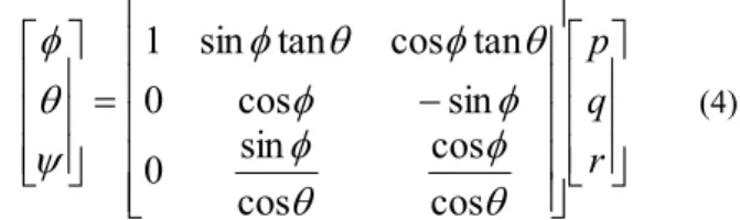
(3)Calculation of roll value (φ), pitch (θ ̇), and yaw (ψ̇) on the gyroscope sensor is obtained through the euler gyroscope angle rotation equation (4).
−
=
r
q
p
cos
cos
cos
sin
0
sin
cos
0
tan
cos
tan
sin
1
(4)Value of roll, pitch, and yaw that has been read on each sensor, then go into complementary filter function with the appropriate formula in the equation below. Complementary filters combine data from these sensors require coefficients for each sensor. KG is a coefficient for gyroscope sensors, whereas KA is a coefficient for accelerometer and magnetometer sensors.
(KG)x( ( Gyroscope)dt
(KA)x( Accelerometer)
Angle=
+
(5) III. RESULTANDDISCUSSION
In this section, we provide the measurement results of the filter design. In order to examine the filter design is working properly, we provide two types of data value, which are measured value using filter and measured value without using filter. Fig. 3 to Fig. 7 show the results of the comparison of the sensor readings by using filters and without using filters for various moisture sensor values. The use of the RC Low Pass Filter results in a more stable reading result than the reading without the use of filters.
Fig. 3. Filter Test Result on Moisture Sensor at Moisture Level 0%
Fig. 4. Filter Test Result on Moisture Sensor at Moisture Level 20%
Fig. 5. Filter Test Result on Moisture Sensor at Moisture Level 32%
Fig. 6. Filter Test Result on Moisture Sensor at Moisture Level 46%
Fig. 7. Filter Test Result on Humidity Sensor at 64%
The moisture sensor is placed in the ground with a depth of 1 meter. The unstable readings are caused by noise. It can be seen in Figs 3 to 7 on the test results without using a filter that the reading has a less stable value. The moisture sensor measures the moisture level of the soil where the sensor is installed. When the soil around the sensor moves then the measurement may yield a different value from the previous measurement. The surge value that occurs can be due to interference from the outside which yields the movement on the ground so that the measurement of moisture becomes less accurate. This is seen in Figs 4, 6, and 7.
The use of RC Low pass filter can reduce the effect of noise on the readings of the moisture sensor. This can be seen from the reading graph using filters resulting in more stable results. Although there is a surge in value due to movement on the ground, the reading results can return to stable again.
Moreover, we expose the average error of each test at a predetermined time, as shown in Table I. The mean value of ADC errors overall on the condition without using filters and using filters has a value of 1 and 0. From the average value of error it is seen that the reading result using the RC Low Pass Filter has better result when compared with the result of reading without using filter.
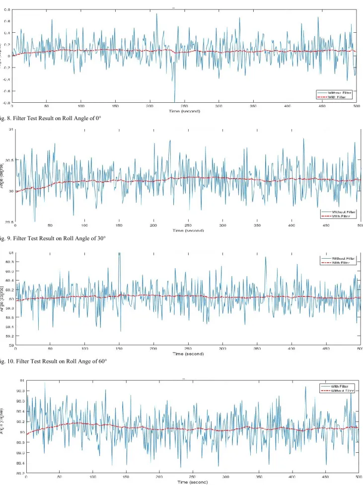
Fig. 8 to Fig. 11 show the results of the comparison of the sensor readings by using filters and without using filters. The use of the Complementary Filter results in a more stable reading result than the reading without the use of filters.
TABLE I. THE RESULT OF LOW PASS FILTER RC ON SOIL MOISTURE LEVEL No Soil Weight (gr) Soil + Water Weight (gr) Calibration of ADC Value Sensor Reading
of ADC Value ADC Error
Without Filter With Filter Without Filter With Filter 1 100 100 1020 1019 1020 1 0 2 100 121 790 789 790 1 0 3 100 132 602 603 602 1 0 4 100 146 400 401 400 1 0 5 100 162 294 293 294 1 0 Average Error 1 0
Fig. 8. Filter Test Result on Roll Angle of 0°
Fig. 9. Filter Test Result on Roll Angle of 30°
Sensor nodes on landslide early detection system are placed in environments potentially to have landslide. The reading from the sensor can be affected by high frequency noise from the outside environment, resulting in unstable readings. It can be seen in Fig. 8 to Fig. 11 with blue line. An example of reading a slope of 60 ° (Fig. 9) shows that the results of measurements without using filters produce results varies reading from a value of 59.2 ° to 61 °. Likewise with test results at angles of 0 °, 30 °, and 90 °. With this unstable reading, it can affect the early landslide detection system that requires accurate data.
The use of complementary filters can help reduce the influence of high frequency noise so that the reading results become more stable. The results of reading the slope angle using complementary filters can produce a more stable reading can be seen in Figs 8 to 11 with a red dashed line graph. It is seen that the reading results using a filter are more stable.
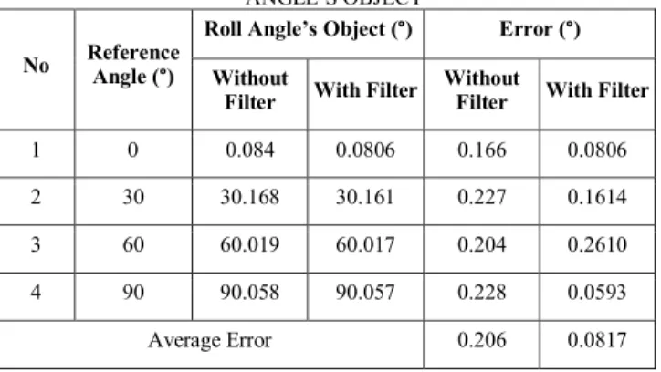
Table II shows the average error of each test at a predetermined time. From the table it can be seen that the results of complementary testing of the tilt angle at a roll angle of 30 ° has the farthest error value of 0.1614°. As for the results of the roll angle readings with the smallest error value found at the reading of 90° angle of 0.059°. The result of using complementary filter to the MPU6050 sensor resulted a better tilt angle reading. By using complementary filter the average error can be decreased from 0,206° to 0,0817°. This result indicated that the performance of complementary filter is good for reducing noise on the MPU6050 sensor reading.
TABLE II. TEST RESULT OF COMPLEMENTARY FILTER ON
ANGLE’S OBJECT
No Reference Angle (
°)
Roll Angle’s Object (°) Error (°) Without
Filter With Filter Without Filter With Filter
1 0 0.084 0.0806 0.166 0.0806 2 30 30.168 30.161 0.227 0.1614 3 60 60.019 60.017 0.204 0.2610 4 90 90.058 90.057 0.228 0.0593 Average Error 0.206 0.0817 IV. CONCLUSION
Based on the results of testing and analysis that has been done the average error of moisture level reading decrease
from 1 to 0 and also at the reading of tilt angle the average error value decreased from 0,206 to 0,0817. It can be concluded that the design of the filter can work well in both cases. This can be seen in the average error results generated on the use of filters that have a smaller result than the results when not using a filter.
ACKNOWLEDGMENT
This work was supported by Superior Research of Higher Education (Penelitian Unggulan Perguruan Tinggi - PUPT) Diponegoro University grant in the fiscal year 2018.
REFERENCES
[1] E. Elnahrawy, “Cleaning and Querying Noisy Sensors,” in WSNA ’03
Proceedings of the 2nd ACM international conference on Wireless sensor networks and applications, 2003, pp. 78–87.
[2] Measurement Computing, Data Acquisition Handbook, 3rd ed. Measurement Computing Corporation, 2004.
[3] B. Alexander, T. Ivan, and B. Denis, “Analysis of noisy signal restoration quality with exponential moving average filter,” in
International Siberian Converence on Control and Communications (SIBCON), 2016, pp. 0–3.
[4] H. Tajiri and teruhisa Kumano, “Input Filtering of MPPT Control by Exponential Moving Average in Photovoltaic System,” in IEEE
International Converence on Power and Energy (PECon), 2012, no. December, pp. 2–5.
[5] L. D. Paarmann, DESIGN AND ANALYSIS OF ANALOG FILTERS : A Signal processing Prespective. Kluwer Academic
Publishers, 2003.
[6] D. I. Stănescu, P. T. Nicolae, I. S. Member, A.-G. I. Dobroiu, and L.
D. Popa, “Designing and Testing of a Second Order Active RC Low
-pass Filter with Different Quality Factors,” in 2014 International Symposium on Fundamentals of Electrical Engineering, 2014, pp. 31–
34.
[7] S. Solution, I. Accelerometer, G. Measurements, B. Platform, S.
Colton, and C. Delphi, “The Balance Filter,” 2007.
[8] K. Nirmal et al., “Noise Modeling and Analysis of an IMU-based Attitude Sensor: Improvement of Pervormance by Filtering and Sensor
Fussion,” 2016.
[9] H. G. Min and E. T. Jeung, “Complementary Filter Design for Angle
Estimation using MEMS Accelerometer and Gyroscope 2 Some
problems in experiment,” pp. 1–11.
[10] T. Ozyagcilar, “Implementing a Tilt-Compensated eCompass using
Accelerometer and Magnetometer Sensors,” Freescale, 2015.
[11] D. D. Quoc, J. Sun, V. N. Le, and N. N. Tan, “Sensor Fusion based on Complementary Algorithms using MEMS,” Int. J. Signal Process.
Image Process. pattern Recognit., vol. 8, no. 2, pp. 313–324, 2015. [12] W. T. Higgins, “A Comparison of Complementary and Kalman