Aalborg Universitet
Development of Next Generation micro-CHP System
Based on High Temperature Proton Exchange Membrane Fuel Cell Technology
Arsalis, Alexandros
Publication date: 2012
Document Version
Publisher's PDF, also known as Version of record
Link to publication from Aalborg University
Citation for published version (APA):
Arsalis, A. (2012). Development of Next Generation micro-CHP System: Based on High Temperature Proton Exchange Membrane Fuel Cell Technology. Department of Energy Technology, Aalborg University.
General rights
Copyright and moral rights for the publications made accessible in the public portal are retained by the authors and/or other copyright owners and it is a condition of accessing publications that users recognise and abide by the legal requirements associated with these rights. ? Users may download and print one copy of any publication from the public portal for the purpose of private study or research. ? You may not further distribute the material or use it for any profit-making activity or commercial gain
? You may freely distribute the URL identifying the publication in the public portal ?
Take down policy
Development of Next Generation
micro-CHP System
Based on High Temperature Proton Exchange
Membrane Fuel Cell Technology
Alexandros Arsalis
Dissertation submitted to the Faculty of
Engineering and Science, Aalborg University
in partial fulfillment of the requirements for the degree of
DOCTOR OF PHILOSOPHY
in
Mechanical Engineering
Development of Next Generation micro-CHP System: Based on High Temperature Proton Exchange Membrane Fuel Cell Technology
Alexandros Arsalis © 2011
All rights reserved. No part of the material protected by this copyright notice may be reproduced or utilized in any form or by any means, electronic or mechanical, including photocopying, recording or by any information storage and retrieval system, without the prior permission of the author.
Printed in Denmark by UniPrint, 2012 First print, January 2012
Development of Next Generation micro-CHP System
Abstract
Novel proposals for the modeling and operation of a micro-CHP (combined-heat-and-power) residential system based on HT-PEMFC (High Temperature-Proton Exchange Membrane Fuel Cell) technology are described and analyzed to investigate the technical feasibility of such systems. The proposed systems must provide electricity, hot water, and space heating for an average single-family household in Denmark. A complete fuel processing subsystem, with all necessary BOP (balance-of-plant) components, is modeled and coupled to the fuel cell stack subsystem. The research project is divided into five main study topics: (a) Modeling, simulation and validation of the system in LabVIEWTM environment to provide the ability of Data Acquisition of actual components, and thereby more realistic design in the future; (b) Modeling, parametric study, and sensitivity analysis of the system in EES (Engineering Equation Solver). The parametric study is conducted to determine the most viable system/component design based on maximizing total system efficiency; (c) An improved operational strategy is formulated and applied in an attempt to minimize operational implications, experienced when using conventional operational strategies; (d) Application of a GA (Genetic Algorithm) optimization strategy. The objective function of the single-objective optimization strategy is the net electrical efficiency of the micro-CHP system. The implemented optimization procedure attempts to maximize the objective function by variation of nine decision variables; (e) The micro-CHP system is optimized by formulating and applying a process integration methodology. The methodology involves system optimization targeting in net electrical efficiency maximization. Subsequently a MINLP (Mixed Integer Non-Linear Programming) problem optimization strategy is applied to minimize the annual cost of the HEN (Heat Exchanger Network). The results obtained throughout this research work indicate the high potential of the proposed micro-CHP system, since net electrical efficiencies of up to 44% were reached, which are far and away higher than heat engine-based systems. Another interesting aspect is the simplicity of the system’s fuel processing subsystem, which makes it more competitive, in terms of commercialization prospects, than other fuel cell-based micro-CHP systems.
Keywords: Fuel cell, PEMFC, PBI, Micro-CHP system, Combined-heat-and-power, Optimization, Pinch analysis, Process integration, Fuel processing, Operational strategy
Author’s address: Alexandros Arsalis, Aalborg University, Department of Energy
Technology, Pontoppidanstræde 101, DK-9220 Aalborg Ø., Denmark
E-mail: [email protected]
Supervisors: Associate Professor Mads Pagh Nielsen, Department of Energy
Technology, Aalborg University, Aalborg Ø., Denmark (primary)
Professor Søren Knudsen Kær, Department of Energy Technology, Aalborg University, Aalborg Ø., Denmark (secondary)
Thesis assessment committee:
Associate Professor Thomas Condra, Department of Energy Technology, Aalborg University, Aalborg Ø., Denmark (chairman)
Professor Per Alvfors, Department of Chemical Engineering and Technology, Division of Energy, KTH-Royal Institute of Technology, Stockholm, Sweden
Dr. Jeppe Grue, Vattenfall A/S Heat Nordic, Aalborg, Denmark
Research program:
Contents
List of Publications 9
Papers included in the thesis 9
Relevant papers not included in the thesis 10
Acknowledgements 11 Abbreviations 13
1 Introduction 15
1.1 Literature Review 15
1.1.1 Fuel Cell Fundamentals 15
1.1.2 Proton Exchange Membrane Fuel Cells 16
1.1.3 High Temperature PEMFC 18
1.1.4 Comparison of Fuel Cell Technologies 19
1.1.5 Combined Heat and Power 20
1.1.6 Micro-CHP Technology 21
1.1.7 Micro-CHP Classification based on the Conversion Process 23
1.2 Comparison Analysis Between the Proposed micro-CHP System and a
Centralized CCGT Power Plant/Heater Combination 27
1.2.1 Efficiency 28
1.2.2 Environmental Considerations 29
1.2.3 Cost 30
1.3 Background and Motivation 30
1.4 Definition of the Research Question 31
1.5 Objectives of the Research Project 31
2 Overview of Research Methodologies 35
2.1 Design of Stationary Fuel Cell Systems 35
2.2 Modeling of Stationary Fuel Cell-based CHP Systems 36
2.2.1 Fuel Processing Subsystem 37
2.2.2 Fuel Cell Subsystem 40
2.2.3 Thermal Management Subsystem 41
3 Description of Publications 43
3.1 Paper I 43
3.2 Paper II 43
3.3 Paper III 44
3.5 Paper V 46
3.6 Overall Evolution of the Configuration Topology 48
4 Summary of Principal Results and Discussion 51
5 Conclusions and Future Work 61
5.1 Conclusions 61
5.2 Future Work 63
List of Publications
Papers included in the thesis
This thesis is based on the work contained in the following five journal articles1, referred to by Roman numerals in the text:
I Arsalis, A., Nielsen, M.P. & Kær, S.K. (2011). Modeling and off-design performance of a 1 kWe HT-PEMFC (high temperature-proton exchange
membrane fuel cell)-based residential micro-CHP (combined-heat-and-power) system for Danish single-family households. Energy 36(2), 993-1002.
II Arsalis, A., Nielsen, M.P. & Kær, S.K. (2011). Modeling and parametric study of a 1 kWe HT-PEMFC-based residential micro-CHP system.
International Journal of Hydrogen Energy 36(8), 5010-5020.
III Arsalis, A., Nielsen, M.P. & Kær, S.K. (2012). Application of an improved operational strategy for a high temperature-proton exchange membrane fuel cell-based micro-combined heat and power system for Danish single-family households. Energy. (submitted)
IV Arsalis, A., Nielsen, M.P. & Kær, S.K. (2012). Modeling and optimization of a 1 kWe HT-PEMFC-based micro-CHP residential system.
International Journal of Hydrogen Energy. (in press)
1. Every research study topic matches exactly with every corresponding journal article publication. Therefore the terms paper/article/study topic are used interchangeably throughout this
V Arsalis, A., Nielsen, M.P. & Kær, S.K. (2012). Optimization of a high temperature PEMFC-based micro-CHP system by formulation and application of a process integration methodology. Energy Conversion and Management. (submitted)
Articles I and II are reproduced with the permission of the publishers.
Relevant papers not included in the thesis
VI Arsalis, A., Nielsen, M.P. & Kær, S.K. (2009). Modeling and simulation of a residential micro-CHP system based on HT-PEMFC technology. EFC09-17045. In European Fuel Cell Technology & Applications - “Piero Lunghi Conference”. Rome, Italy, December 15-18.
Acknowledgements
This PhD research project was supported by Danish companies Dantherm Power and Danfoss. It was also co-funded by the HyFC (Hydrogen Fuel Cell Academy) and Aalborg University.
Thanks to my academic supervisors Mads Pagh Nielsen and Søren Knudsen Kær for providing valuable advice, comments and suggestions throughout the research study.
Special thanks go to Anders Korsgaard for providing simulation models in the initial stages of the project, and also prompt feedback, when needed, throughout the project.
I would also like to thank my colleagues at the Fuel Cell Research Program for exchanging fruitful ideas on the research project.
Finally, I am indebted to my family who has helped me, while I devoted time and energy to this research work.
Alexandros Arsalis Aalborg October 2011
Abbreviations
AFC Alkaline Fuel Cell
BOP Balance-of-Plant CHP Combined Heat and Power
EES Engineering Equation Solver
GA Genetic Algorithm
GAMS General Algebraic Modeling System HEN Heat Exchanger Network
HHV Higher Heating Value
HT High Temperature
ICE Internal Combustion Engine
IRR Internal Rate of Return LHV Lower Heating Value
LT Low Temperature
MCFC Molten Carbonate Fuel Cell MEA Membrane Electrode Assembly
MINLP Mixed Integer Non-Linear Programming PAFC Phosphoric Acid Fuel Cell
PBI Polybenzimidazole
PEMFC Polymer Electrolyte Membrane Fuel Cell
RC Rankine Cycle
RE Reciprocating Engine
RH Relative Humidity
SC Steam-to-Carbon ratio
SE Stirling Engine
SMR Steam Methane Reformer SOFC Solid Oxide Fuel Cell
VI Virtual Instrument
(This is an example of an empty page. A white rectangle is drawn on top of the page number.) (This
1 Introduction
This chapter presents an overall literature review on the fuel cell and micro-CHP technologies. Further on, the background and motivation for the research study are explained, and the project objectives are outlined. Finally, the research question is posed and analyzed.
1.1 Literature
Review
Starting from the general field of fuel cell technology and combined heat and power (CHP), the literature review is narrowed down to the PEMFC (Proton Exchange Membrane Fuel Cell) type, and more specifically to the PBI type. In addition, CHP technology is analyzed and broken down to small-scale residential micro-CHP technology. The different types of micro-CHP systems are described to indicate their advantages and disadvantages. Finally an overview of the implications and prospective of micro-cogeneration technology is given.
1.1.1 Fuel Cell Fundamentals
Fuel cell technology is based on the principle of direct electrochemical energy conversion (Barbir, 2005; Larminie & Dicks, 2003; Mench, 2008; O’Hayre, Colella, Cha, & Prinz, 2009). In other words, fuel cells are not heat engines since no combustion takes place. Also, chemical energy input is converted to electrical energy, without the intermediate step of mechanical energy production, as in heat engines. In terms of electrochemistry, fuel cells are also related to batteries, but the difference is that fuel cells are not depleted as batteries. Figure 1 illustrates the operating principle of fuel cell technology. Two electrodes exist in a fuel cell arrangement, namely cathode and anode, which are separated by the electrolyte. The oxidant and the fuel enter the fuel cell stack through the cathode and the anode, respectively. The fuel cell
reaction typically produces water, which is at a higher temperature than the reactants. More importantly, this exothermic reaction is also associated with the production of electricity with an external load between the two electrodes. Fuel cell performance is assessed with the aid of voltage-current curves (polarization curves), plotted for different loads. These curves can also illustrate the overpotentials (losses), which are divided between activation, ohmic and concentration losses.
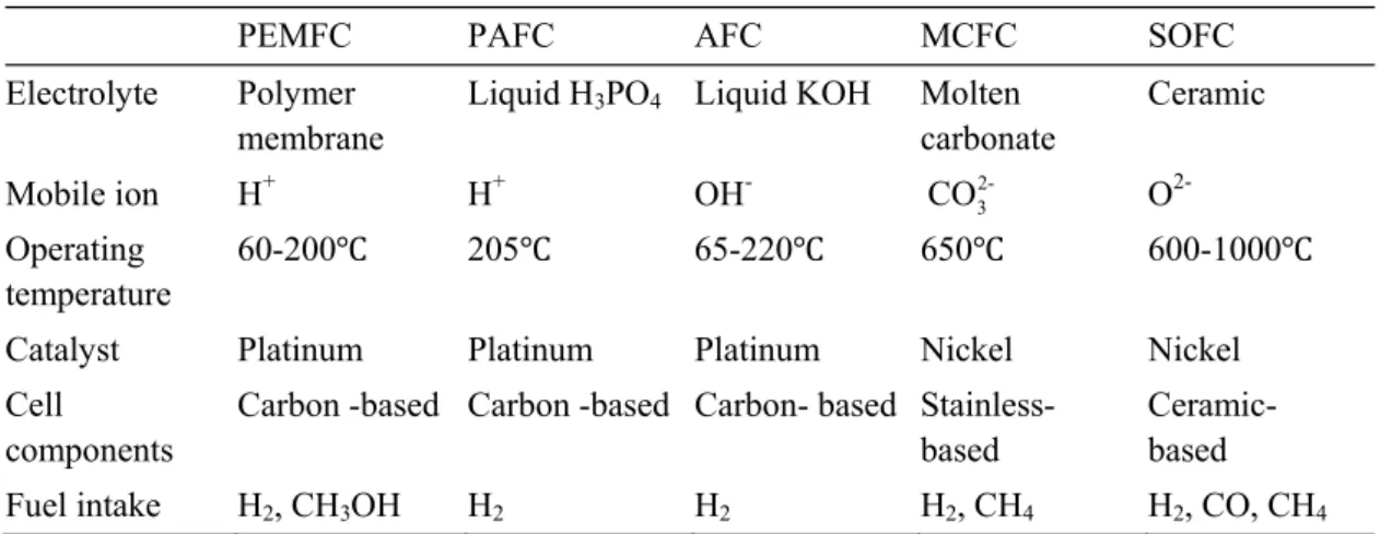
The five main fuel cell types are distinguished by their electrolyte material and they are the following: (a) Polymer Electrolyte Membrane Fuel Cell (PEMFC) (b) Phosphoric Acid Fuel Cell (PAFC), (c) Alkaline Fuel Cell (AFC), (d) Molten Carbonate Fuel Cell (MCFC), (e) Solid Oxide Fuel Cell (SOFC). Every fuel cell type has some distinctive characteristics in terms of operational temperature, pressure, fuel intake and tolerance, building materials (electrolyte, catalyst, cell components), and performance. These characteristics result in advantages or disadvantages, depending on the application, as it will be shown in the following sections. A summary of these characteristics is given in Table 1.
Table 1 Description of major fuel cell types.
PEMFC PAFC AFC MCFC SOFC
Electrolyte Polymer membrane
Liquid H3PO4 Liquid KOH Molten
carbonate Ceramic Mobile ion H+ H+ OH- 2-3 CO O 2-Operating temperature 60-200 205 65-220 650 600-1000
Catalyst Platinum Platinum Platinum Nickel Nickel
Cell components
Carbon -based Carbon -based Carbon- based Stainless-based
Ceramic-based
Fuel intake H2, CH3OH H2 H2 H2, CH4 H2, CO, CH4
1.1.2 Proton Exchange Membrane Fuel Cells2
The following electrochemical half reactions in the PEMFC occur simultaneously in the two electrically conductive electrodes,
+ -2 + -2 2 H 2H +2e (anode) 1 O +2H +2e H O (cathode) 2 (1)
The most common material for the polymer membrane of the ionically conductive material is NafionTM(Barbir, 2005). The membrane must be thin,
flexible and coated with a platinum-based catalyst, while the electrode support material must be a porous carbon. The total assembly is a sandwich structure, namely the Membrane Electrode Assembly (MEA), connecting the anode-catalyst-membrane-catalyst-cathode components. The fuel cell operating temperature for NafionTM-based fuel cell stacks cannot exceed 90°C, because the membrane requires continuous hydration to maintain its conductivity capabilities. Therefore a rigorous water management is required throughout the operation.
load e
-product gases & depleted fuel out
product gases & depleted oxidant out
fuel in oxidant in anode electrolyte cathode (CO) (CO) (CH4) OH -H+ CO3= O= H2 H2O H2 H2 CO2 H2O H2 H2O O2 H2O O2 H2O O2 CO2 O2 AFC PAFC PEMFC MCFC SOFC
Figure 1 Schematic of the operating principle for different fuel cell types [based on the description found in (Barbir, 2005)].
To maintain operation within this low temperature range only platinum-based catalysts and polymer membranes can be used. This means that the building
cost of this fuel cell technology will remain high. On the other hand, power densities are higher than other fuel cell types, ranging from 300 to 1000*mW/cm2 (O’Hayre et al., 2009). Further on, on-off operations and start-ups are also faster than other fuel cell technologies (e.g., SOFC). For these reasons, PEMFC is the primary fuel cell technology for vehicular and portable applications (<1 kWe) (Mench, 2008). In addition, due to their high sensitivity
and low tolerance to sulfur and carbon monoxide, hydrogen is usually preferred as the system fuel, although effort has been made to use other more convenient fuelling options, such as methanol. Usage of fossil fuels, such as natural gas, can add a further cost burden to the fuel cell system’s capital cost, because more complicated fuel processing will be required.
1.1.3 High Temperature PEMFC
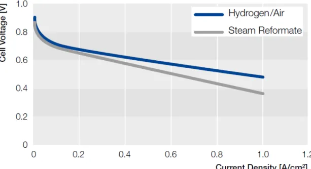
The previous section discussed the implications encountered when operating NafionTM-based PEMFCs. The disadvantage of operating near the two-phase region can be alleviated with the utilization of a phosphoric acid doped polybenzimidazole (PBI) material (see Figure 2 and Figure 3). This material is doped with a strong acid, such as H3PO4, to create an ionic conductivity. This
material allows operation between 120 to 200°C (Büchi, Inaba, & Schmidt, 2009; O’Hayre et al., 2009; Jianlu Zhang et al., 2006), and therefore no membrane hydration is required, leading to a relaxation of the water management requirements. More importantly the performance of the PBI membrane, in terms of conductivity, remains comparable to the one for NafionTM membranes.
The high operational temperature contributes in higher tolerances to sulfur and carbon monoxide, and also yields a higher quality exhaust mixture out of the fuel cell stack. Moreover PBI membranes offer increased mechanical strength, lower building costs, and thermal stability (Jianlu Zhang et al., 2006).
On the other hand, several disadvantages are associated with PBI membranes. The most significant ones include slow kinetics of the oxidant reduction reaction, membrane oxidative degeneration, challenging electrocatalyst ink catalyst blending with the PBI material, and durability issues in relation to acid-leaching (O’Hayre et al., 2009).
Figure 3 HT-PEMFC MEA performance polarization curve (Stolten, 2010). 1.1.4 Comparison of Fuel Cell Technologies
PAFC- and MCFC-based systems are generally applicable for larger-scale applications (e.g. 200 kWe systems) and therefore they are not suitable for micro-CHP system applications (Barbir, 2005; Barclay, 2006; Larminie & Dicks, 2003; O’Hayre et al., 2009). In particular PAFC technology is a mature technology, with proven reliability/long-term performance and low-cost electrolytes (O’Hayre et al., 2009). On the other hand, it requires expensive platinum catalysts, is susceptible to carbon dioxide and sulfur poisoning, and the electrolyte is a corrosive liquid that must be replenished during operation (O’Hayre et al., 2009). In addition, PAFC technology has reached a certain level of limitation, in regards to research improvement as indicated in the literature (Larminie & Dicks, 2003). MCFC technology requires very careful operation and complex BOP components (O’Hayre et al., 2009), including CO2 recycling, corrosive molten electrolytes, and relatively expensive
materials. Also, degradation and lifetime issues have been reported in the literature (O’Hayre et al., 2009).
SOFC is a promising fuel cell technology (Zink et al., 2007) and therefore still under development. Nevertheless, current SOFC-based systems have several disadvantages, as compared to HT-PEMFC technology. These include slower start-up times (due to their higher operational temperature), need for air and fuel preheaters and more complex cooling systems (Larminie & Dicks, 2003; O’Hayre et al., 2009). Also the need for higher temperature operation suggests greater heat losses and thereby more expensive insulation is required. Finally, it requires pressurization of fuel and air, which suggests greater BOP component (e.g. air compressor) power losses. On the other hand, SOFC-based systems allow the use of carbon monoxide content in the reformate gas as fuel, with the use of an internal reforming process (without the need of a separate unit) (Arsalis, 2007; Calise, Dentice d’Accadia, Palombo, et al., 2006), which suggests a significant advantage over other fuel cell technologies. Also the high reaction rates achievable by the SOFC technology allow the use of cheaper catalysts and thereby reducing their capital cost (Larminie & Dicks, 2003).
1.1.5 Combined Heat and Power
The conventional method of covering electrical, heating (e.g. hot water) and cooling (e.g. space cooling) load demands is by purchasing electricity from the electricity network grid and with a fossil fuel-fired boiler. A different method of covering these loads is combined-heat-and-power (CHP) (or cogeneration), which can aid in the reduction of running (fuel) costs and in effect increase the total efficiency. Therefore, CHP is defined as the combined generation of electrical power and heat from a single chemical energy source.
The useful recovery of the biggest portion of waste heat can increase the system efficiency from 30-40%, up to 75-90%, depending on the application and the size of the system. In addition to the efficiency increase, CHP can also lead in the reduction of emissions, since a smaller amount of fuel is required. Therefore CHP is the preferred choice of generating electricity and heat, provided the capital cost is within viable limits in terms of lifetime and payback time.
Cogeneration systems can be distinguished into two main configurations. The first configuration is the production of a high temperature fluid product, which can be used to generate electricity (e.g. gas turbine), while the exhausted heat is at a low temperature and can be used throughout several thermal processes for district heating purposes, or in some cases for additional production of electricity (Arsalis, 2008). Alternatively, the high temperature
fluid product (e.g. from a waste-to-energy power plant) can be used in a heat recovery steam generator to produce superheated steam for a Rankine cycle (steam turbine) process. In some cases it is also possible to use the hot gases directly into a Brayton cycle (gas turbine), without the need of a heat recovery boiler.
1.1.6 Micro-CHP Technology
For the purposes of this research study, micro-CHP (Dentice d’Accadia, Sasso, Sibilio, & Vanoli, 2003; Ferguson, 2004; Gunes & Ellis, 2003; Hawkes & Leach, 2005a, 2005b, 2007, 2008, 2009; Hawkes et al., 2007, 2006; Hubert, Achard, & Metkemeijer, 2006; Pehnt et al., 2006) is defined as the simultaneous production of electricity and heat in a residential application for systems up to 5 kWe. Micro-CHP systems typically have (or expected to have)
a lifetime of ten to twenty years, which is comparatively lower than large-scale CHP systems. They are designed to exhibit minimum total efficiencies of 75%. In order for these systems to make a breakthrough to the power and heat market, many requirements should be satisfied. The main requirements are (a) low cost, (b) compact volume and size, (c) easy installation and (d) automated operation without demanding routine maintenance checks.
Depending on the load profile, an appropriate heat-to-power ratio must be selected based on the demand. For example, a system with a high heat-to-power ratio will be inappropriate for a household requiring a high electrical load. Nowadays, most newly-built households have efficient insulation and are more ‘electricity-demanding’ than ‘heat-demanding’, as compared to the past. Therefore, in general, even lower heat-to-power ratios will be required in the future. Also the production of additional heat, if needed, can be provided by condensing gas-fired boilers, which have become very efficient in recent years, with efficiencies near or above 90% (Hawkes & Leach, 2005a). Therefore, focus is primarily given on systems exhibiting high electrical efficiencies, rather than thermal efficiencies.
For the better utilization and distribution of power and heat, micro-CHP systems must be grid-interconnected, although micro-CHP systems can also operate in a stand-alone (island) mode. The reason for grid-interconnection is that a stand-alone micro-CHP system will be required to operate continuously within an electricity-led operational strategy. As a consequence of this practice, large amounts of heat will have to be vented to the atmosphere. Otherwise a thermal storage tank of massive dimensions will be required, which is inappropriate and unacceptable for a residential design. Another consequence is also the rate of heat loss, which increases with the increasing size of the
thermal storage tank3. In addition, the benefit of importing cheap electricity (e.g. from wind power) from the network grid will not be utilized. It should be noted though, that import/export of electricity should be minimized in order for the application to conserve its on-site power generation/consumption characteristics. On-site power generation minimizes transmission losses, which can have an even greater factor if the power transmitted has a high purchase cost.
Figure 4 Classification of micro-CHP technologies based on the conversion process.
Japan has been the leading market for micro-cogeneration in the last decade, but recently a rapid growth of the technology has also been observed in Europe. An increase in the sales of micro-CHP systems by around 25%, between 2009 and 2010, suggests that the market will grow even at higher proportions in the near future. 20,000 to 70,000 micro-CHP units are expected to be sold by 2015 (Brown, 2011).
1.1.7 Micro-CHP Classification based on the Conversion Process
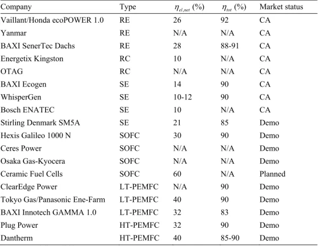
The conversion process of a micro-CHP system can be based on fuel-air combustion or direct electrochemical conversion (Pehnt et al., 2006). The classification of micro-CHP systems in regards to their conversion process is shown in Figure 4. Combustion-based systems combust the fuel-air mixture at a high temperature and eventually mechanical energy is produced. The mechanical energy is then used to drive an electric generator and produce electrical energy. Combustion-based micro-CHP systems are based on various thermodynamic cycles, including reciprocating engines (Otto cycle), steam engines (Rankine cycle) and Stirling engines (Stirling cycle). Alternatively, the conversion process can be based on direct electrochemical conversion from chemical energy to electrical energy (i.e. fuel cell technology). As indicated in the previous section, in addition to the production of electrical energy, the conversion process also results in the production of heat, which can be recovered as needed. The status of the different technologies is discussed in the following subsections and summarized in Table 2.
Reciprocating Engines
A reciprocating engine (RE) based on a spark-ignited, internal combustion piston-cylinder engine operates on the Otto thermodynamic cycle, which includes four consecutive processes: (a) isochoric, (b) isentropic expansion, (c) isochoric, and (d) isentropic compression.
The performance of current RE-based micro-CHP systems is the most promising, as compared to other heat engine-based micro-CHP systems. This technology is also the most mature in the micro-cogeneration market, since a range of different systems have been commercially available in the last decade (Pehnt et al., 2006). Vaillant/Honda has reported electrical and total efficiencies of 26.3% and 92%, respectively, for their ecoPOWER 1 kWe unit
(Energy Efficiency News, 2011; Vaillant, 2011). Japanese company Yanmar has also developed an ICE unit with an electrical power output of 5 kWe (Dijkstra, 2010). Finally, BAXI has developed a 5.5 kWe system (SenerTec
Dachs) with an electrical and total efficiencies ranging at 28 and 88-91% (BAXI, 2011a; Thomas, 2008), respectively.
Rankine Cycle
A Rankine cycle-based (RC) engine is based on a thermodynamic cycle consisting of four consecutive ideal processes: (a) isobaric, (b) isentropic, (c) isobaric, and (d) isentropic. The liquid water is heated (typically with a boiler) until superheated steam is produced. The superheated steam is then used to
drive a steam expander, producing mechanical energy. The mechanical energy is then converted to electrical energy by means of an electric generator.
In 2006, German company OTAG developed a 3 kWe unit (Slowe, 2010),
while in 2010, UK-based company Energetic Group has revealed a 1 kWe unit,
‘Kingston’, which is expected to have an electrical efficiency at around 10% (Energetix Group, 2010).
Table 2 Competing micro-CHP technologies: Status and performance summary.
Company Type el net, (%) tot(%) Market status
Vaillant/Honda ecoPOWER 1.0 RE 26 92 CA
Yanmar RE N/A N/A CA
BAXI SenerTec Dachs RE 28 88-91 CA
Energetix Kingston RC 10 N/A CA
OTAG RC N/A N/A CA
BAXI Ecogen SE 14 90 CA
WhisperGen SE 10-12 90 CA
Bosch ENATEC SE 10 N/A CA
Stirling Denmark SM5A SE 21 85 Demo
Hexis Galileo 1000 N SOFC 30 90 Demo
Ceres Power SOFC N/A N/A Demo
Osaka Gas-Kyocera SOFC N/A N/A Demo
Ceramic Fuel Cells SOFC 60 N/A Planned
ClearEdge Power LT-PEMFC N/A 90 Demo
Tokyo Gas/Panasonic Ene-Farm LT-PEMFC 40 90 Demo
BAXI Innotech GAMMA 1.0 LT-PEMFC 32 83 Demo
Plug Power HT-PEMFC 32 90 Demo
Dantherm HT-PEMFC 40 85-90 Demo
CA: Commercially available
Stirling Engines
A Stirling engine (SE) is an external combustion engine operating on the Stirling thermodynamic cycle, which includes four consecutive processes: (a) isothermal expansion, (b) isochoric cooling, (c) isothermal compression, and (d) isochoric heating. The SE typically includes three pistons, two outer and one displacer. The latter circulates the cylinder products into the chamber, which is cooled or heated by their respective outer streams. The two outer pistons can be used to regulate the capacity of the combustion process.
The main characteristics of Stirling engines, as compared to other heat engines, include adequate part-load performances, low emission rates and low vibration and noise levels. In addition, the external combustion, closed cycle
operational nature of SE restricts the exposure of the moving parts of the engine to the products of combustion. Thereby component degradation is minimized. In addition, SEs allow greater fuel flexibility, which means that liquid or gaseous fuels, biofuels, etc. are compatible (Pehnt et al., 2006).
SE is not a mature technology in the micro-cogeneration marketplace, when compared to RE-based systems. Nevertheless, because of the advantages outlined above, the technology has attracted a significant interest in recent years. BAXI develops a 1 kWe/6 kWth unit, so-called Ecogen, which is capable
of achieving electrical and total efficiencies of 14% and 90%, respectively (Gummert, 2008). WhisperGen develops a 1.2 kWe/8 kWth unit, which is
capable of achieving electrical and total efficiencies of 10-12% and 90%, respectively (Pehnt et al., 2006). Bosch develops a 1 kWe/6 kWth unit,
so-called ENATEC, which is capable of achieving an electrical efficiency of 10% (Beckers, 2006). Finally, Stirling Denmark has developed a larger-scale demonstration unit (9 kWe/25 kWth), which has been tested to perform
electrical and total efficiencies at 21% and 85%, respectively (Thomas, 2008). Fuel Cells Systems
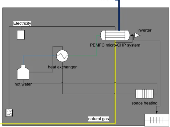
Fuel cell-based micro-CHP systems (see Figure 5) are either based on the PEMFC or SOFC types (Inui, Yanagisawa, & Ishida, 2003). Fuel cells are currently the least mature technology in the area of micro-CHP systems, when compared to heat engine-based applications. Nevertheless, because of their promising features, primarily low emissions and high net electrical efficiencies, these systems have attracted a lot of interest for research and development. In addition, some justification also comes from synergies with other renewable energy sources (e.g. wind power). In this sense, a PEMFC-based system is capable of providing fast regulation services to the grid responsible.
BAXI has developed a 1 kWe/1.7 kWth LT-PEMFC-based unit (Innotech
GAMMA 1.0), which is capable of achieving electrical and total efficiencies of 32% and 83%, respectively (BAXI, 2011b). Korean company ClearEdge Power has been developing a 5 kWe LT-PEMFC-based unit with a total system
efficiency reaching 90% (ClearEdge Power, 2011). Tokyo Gas, in association with Panasonic, has been developing a 0.75 kWe LT-PEMFC-based unit
capable of achieving an electrical efficiency of 40%, while the total system efficiency is expected to reach 90% (Tokyo Gas Ltd., 2011).
Hexis has developed a 1 kWe/2 kWth SOFC-based unit (Galileo 1000 N),
which is capable of achieving electrical and total efficiencies of 30% and 90%, respectively (Callux, 2009). Some other companies, namely Osaka Gas-Kyocera, Ceres Power and Ceramic Fuel Cells are also in the process of developing SOFC-based micro-CHP units (Delta Energy & Environment Ltd,
2010). In particular, Ceramic Fuel Cells is planning to develop an SOFC-based unit (1.5 kWe/0.5 kWth), with a remarkable electrical efficiency reaching up to
60% (Ceramic Fuel Cells Ltd., 2010). Plug Power has developed a 5 kWe HT-PEMFC-based unit, which is capable of achieving electrical and total efficiencies close to 32% and 90%, respectively (Vogel & Tsou, 2007).
natural gas heat exchanger
PEMFC micro-CHP system
hot water space heating Electricity electricity import/export exhaust inverter
Figure 5 Arrangement of a residential PEMFC-based micro-CHP system.
In Germany, a residential fuel cell program, named “Callux”, has been initiated in 2008, and the first phase is expected to be completed in 2012. The consortium combines the expertise of several industrial bodies and companies. The fuel cell manufacturers involved in this project include companies such as BAXI, Hexis and Vaillant (Callux, 2009). Several units have already been installed and currently, they are being tested in German households.
In Denmark, a micro-CHP project has been initiated in 2006, managed by a national consortium and consisting of nine companies and governmental bodies, such as the Danish Energy Agency. The consortium combines all the expertise necessary to develop, test, and demonstrate micro-CHP systems. The Danish Ministry of Climate and Energy finances the project by 40% of the total cost. The project is scheduled to be completed by 2012, and will test units based on various fuel cell technologies, such as NafionTM-based PEMFC,
PBI-based PEMFC and SOFC. It is divided into three phases, and two fuel types are being tested: hydrogen and natural gas. The choice of fuel depends on the fuel cell technology and its availability at the installation site. A preliminary assumption concerning the operational control of the system, indicated that the electrical load must be fulfilled, but also the design should secure the right amount of heat will be available on demand for the space heating and hot water loads. Further on, an auxiliary burner for peak production of thermal energy is under consideration to be integrated to the end-user system (Danish Micro-CHP, 2009; Korsgaard, Nielsen, & Kær, 2008).
The HT-PEMFC-based micro-CHP units are developed by Dantherm Power and operate on natural gas. Experimental tests, with pure hydrogen fuel, showed start-up times of 30 to 60 minutes, with an electrical efficiency of 40% (hydrogen fuel, LHV-based). From the operating point of the finalized design, an efficiency of 50% is expected (hydrogen fuel, LHV-based). Further experimental tests and calculations showed a potential system efficiency of 85 to 90% (LHV-based) (Danish Micro-CHP, 2009). A fast adaption to load variations was also observed. In the first phase, Danish micro-CHP developed unit prototypes with PEMFC and SOFC technologies. In the second phase, ten micro-CHP units are scheduled to be installed and tested at selected consumer households in the municipalities of Lolland and Sønderborg. In the third and last phase, micro-CHP systems will be installed and demonstrated at around 100 households in the two aforementioned municipalities. This will allow the Danish micro-CHP system project to gather and analyze realistic experiences related to installation, operational procedures, maintenance needs and also consumer satisfaction (Danish Micro-CHP, 2009). Currently, HT-PEMFC activities are on standby, pending durability issues to be resolved.
1.2 Comparison Analysis Between the Proposed micro-CHP
System and a Centralized CCGT Power Plant/Heater
Combination
In this section the proposed HT-PEMFC-based micro-CHP system is compared to a more conventional combination of producing electricity and heat for a single-family household in Denmark. The best available technology today is analyzed and set as a suitable baseline for comparison with the proposed micro-CHP system.
It should be noted though, that combined cycle gas turbine (CCGT) and micro-CHP systems are not necessarily in competition with each other, because they can coexist ‘peacefully’ in the future. If both technologies are used in parallel, more options will be available and therefore the better utilization of
resources (e.g. natural gas) will improve. In other words, energy availability and reliability will improve, because dependency to the network grid will decrease, and therefore grid congestions and blackout events will diminish (Chicco & Mancarella, 2009; Praetorius et al., 2009). In addition, the current centralized power production system status-quo will shift towards a more competitive regime, with obvious benefits (Praetorius et al., 2009). Therefore, it should be strongly emphasized that the purpose of this research work is not the investigation of a proposed replacement of centralized CCGT power plants, but rather the replacement of aging natural gas boilers4, as already noted. Therefore the discussion below is only provided for comparison purposes.
Centralized power generation is considered more conventional and power plants are available in various configurations and based in different technologies. The most significant ones are the following: Steam turbines (ST), gas turbines (GT) and CCGT. The latter type is considered to be the most advanced technology, exhibiting overall efficiencies close to 60% (Lund, 2008; Praetorius et al., 2009). It combines the gas turbine (Brayton) and steam turbine (Rankine) thermodynamic cycles, where the former is the topping cycle and the latter the bottoming one. In addition, some other, more novel, central power plants designs have been under investigation in recent years. These include hybrid systems, which combine high temperature fuel cells with turbine cycles (i.e. SOFC-GT, SOFC-ST, SOFC-GT-ST and MCFC-GT).
Therefore the following hypothetical question must be answered:
Can the proposed system compete with centralized CCGT power plants and heat-only boilers which are in widespread use in single-family households today?
To answer the above question, a number of comparison parameters are considered in order to distinguish the characteristics, including advantages and disadvantages, of the two technologies. The following analysis is performed in terms of efficiency, environmental considerations and cost.
1.2.1 Efficiency
The efficiency of a CCGT power plant is lower than the efficiency of the proposed system in many ways. At nominal load, modern CCGT systems can exhibit electrical efficiencies up to 60%5 (Ang, Fraga, Brandon, Samsatli, & Brett, 2011), which is higher than the expected electrical efficiency of the
4. This is also the target of the Danish micro-CHP project (Danish Micro-CHP, 2009).
proposed system. On the other hand, both systems must operate both at nominal and part-load. At part-load, the electrical efficiency of the CCGT will decrease6 (Kehlhofer, Bachmann, Nielsen, & Warner, 1999), while the electrical efficiency of the proposed system will increase. For example, a CCGT plant with a nominal load efficiency of 60%, will have a decreased efficiency of 52% at 50% part-load (estimation based on empirical data found in (Kehlhofer et al., 1999)).
Further on, due to distribution and transmissions losses, around 6 to 10% of the efficiency is lost in the case of CCGT (Al-Sulaiman, Hamdullahpur, & Dincer, 2011; Lund, 2008), while in the case of the proposed system, there are practically no such losses, because the power is produced and consumed on-site (Raven & Verbong, 2007). It should be noted though that this assumption is only valid provided electricity is not exported by the proposed system to the grid (electricity-led operation).
In terms of overall efficiencies, the proposed system can reach efficiencies up to 91%, which is significantly higher than the corresponding efficiencies for CCGT, especially in the case where the exhausted heat of the power plant cannot be usefully utilized (Ang et al., 2011; Westner & Madlener, 2011).
Finally innovative control techniques, such as virtual control of many micro-CHP systems (virtual power plant), can aid in a more efficient operation of the micro-CHP systems, since neighboring micro-CHP systems can operate jointly, transmitting heat and power, as needed (Delta Energy & Environment Ltd, 2010; Praetorius et al., 2009; Raven & Verbong, 2007).
1.2.2 Environmental Considerations
Fuel cell technology features high electrical and total efficiencies, which in terms of environmental benefits translate to lower fuel consumption and decreased CO2 emissions, as compared to a CCGT/boiler combination
(Praetorius et al., 2009). The Kyoto agreement has prompted the EU to adopt energy policies that favor power and heat production with reduced greenhouse emissions (De Paepe & Mertens, 2007; Praetorius et al., 2009; Ropenus, Schröder, Costa, & Obé, 2010). Therefore, it is expected that the proposed system will be offered with several benefits, such as lowered taxation, subsides, etc. Therefore energy policies can further favor the adoption of decentralized systems, such as the proposed system, even though their (actual) total cost will remain higher than CCGT/heater per kWh.
6. In CCGT power plants, without supplementary firing, the total plant efficiency primarily depends on the degree of heat recovery, the GT efficiency and the size of the plant (Kehlhofer et
The main problem with the proposed system, in terms of emission rates, is that the emissions will be exhausted in urban areas. Thereby CCGT is more emissions attractive, at least locally, in the sense that centralized power plants are typically located in rural areas (Chicco & Mancarella, 2009).
1.2.3 Cost
Currently fuel cell-based micro-CHP systems are not commercialized and therefore an estimation of their total cost cannot be accurately calculated. Nevertheless, the current capital cost of a fuel cell system is estimated to be very high and not competitive in terms of market diffusion (Chicco & Mancarella, 2009; Woudstra, van der Stelt, & Hemmes, 2006). A threshold point7 must be reached, to allow the proposed system to compete with centralized power plants. The total cost includes the operating (fuel) cost, capital cost, maintenance cost and taxation cost. In addition the lifetime of the system must be known.
The proposed system can achieve high overall efficiencies and therefore can lead in fuel consumption reductions. Therefore, compared to the lower overall efficiencies of CCGT power plants at both full-load, and especially at part-load operation, the proposed system is more attractive in terms of fuel savings.
Finally in terms of lifetime and reliability, the proposed system has still a long way to prove itself (Delta Energy & Environment Ltd, 2010). Both the fuel cell stack and fuel processing degradation and catalyst deactivation issues have to be resolved, before the proposed system is able to match CCGT or other heat engine-based technologies.
1.3 Background and Motivation
The main motivations for the development of HT-PEMFC based micro-CHP systems for Danish single-family households are the following:
The proven ability of fuel cell technology to achieve higher operational efficiencies (electrical and overall), with lower emissions as compared to other more conventional technologies (e.g. heat engines) (Barbir, 2005; Georgopoulos, 2002; Kim, von Spakovsky, Wang, & Nelson, 2010; Larminie & Dicks, 2003; O’Hayre et al., 2009);
The need for the replacement of gas-fired furnaces in Danish single-family households with more efficient alternatives (Danish
7. The investment cost for a typical modern CCGT-CHP power plant is estimated at around 1200 €/kWe, with a depreciation period of 30 years and IRR of 7.4% (Westner & Madlener,
CHP, 2009; Korsgaard et al., 2008). There is an increasing demand for cleaner and more efficient energy production in conjunction with the increasing price and depletion of fossil fuels. Moreover, higher operational efficiencies suggest lower operational costs (Arsalis, 2008);
The HT-PEMFC technology utilizes PBI membranes, operating at temperatures between 140 to 200 . Therefore, this technology allows enhanced electrochemical kinetics, simpler water management and cooling, and also useful waste heat can be recovered (Büchi et al., 2009; Korsgaard, Nielsen, Bang, & Kær, 2006; Korsgaard, Refshauge, Nielsen, Bang, & Kær, 2006; Stolten, 2010; Jianlu Zhang et al., 2006). In addition lower quality reformed hydrogen may be used as fuel (Jianlu Zhang et al., 2006), suggesting cheaper and simpler fuel processing subsystems are required.
1.4 Definition of the Research Question
Based on the literature review on micro-CHP technology, and the background and motivation, analyzed and explained in the previous sections, the main research question can be formulated:
What are the prospects of 1 kWe HT-PEMFC-based micro-CHP systems to replace gas-fired burners in Danish single-family households in the context of a technical feasibility study?
To answer this question, this research effort establishes the methods and framework for physical and empirical parametric modeling of the HT-PEMFC-based micro-CHP system, including its subsystems/components at a level appropriate for conceptual and preliminary design. The developed system must be validated and throughout a process of computational simulations, including design and off-design operational modes, parametric studies, sensitivity analysis, development of improved operational strategies, and application of optimization strategies (genetic algorithm, pinch analysis and process integration methods), conclusions are drawn on the proposed system potential.
1.5 Objectives
of
the Research Project
The overall goal of this research work is to develop a HT-PEMFC-based micro-CHP system to replace natural gas heating units in Danish households. A 1 kWe (nominal power rate) grid-connected micro-CHP system can fulfill
the needs of such a household (average four person family residence in Denmark). To model and then analyze the micro-CHP system configurations as realistically as possible, detailed system and component thermodynamic, kinetic and geometric models are developed, implemented, and validated. Then by means of different studies, such as parametric studies, sensitivity analysis, genetic algorithm optimization (Chong & Zak, 2001; Ravindran, Ragsdell, & Reklaitis, 2006), and optimization using process integration techniques (pinch analysis) (Biegler, Grossmann, & Westerberg, 1997; Kemp, 2007; Sieniutycz & Jezowski, 2009; Smith, 2005), the system is thoroughly analyzed in the context of a technical feasibility study. Therefore the full advantages of such a HT-PEMFC-based micro-CHP system over more conventional systems can be extracted and analyzed.
The research project is split into five main topics/studies (shown in Figure 6), which can be summarized as follows:
Development of the system in LabVIEWTM for future use with data acquisition hardware and laboratory tests of actual components;
Development of the system in EES. Subsequent analysis using parametric study and sensitivity analysis methodologies;
Investigation of the simulation model performance at different operational loads and formulation of an improved operational strategy;
Optimization of the system by use of a genetic algorithm optimization strategy;
Further optimization using pinch analysis and process integration techniques. Objective functions are formulated for the maximization of the net electrical efficiency and minimization of total HEN cost. Thus, this research project includes the following tasks:
Perform a literature review on fuel cell- and conventional-based micro-CHP systems;
Become familiar with the previously developed HT-PEMFC-based micro-CHP system by A. Korsgaard (Korsgaard et al., 2008);
Modify existing or develop new models/components required for the micro-CHP system. These models include: HT-PEMFC stack, SMR reactor, WGS reactor, catalytic combustor, heat exchangers, steam generator, water pump, air blower, thermal storage tank;
Design, model and optimize the total system to implement the outlined studies;
Examine the off-design operational behavior of the system in terms of efficiency and emissions;
Analyze the results and draw conclusions.
Figure 6 Information flow within the research project effort.
To eliminate possible confusion, while reading this thesis work, the following assumptions are given:
The fuel cell type was predetermined to be of the HT-PEMFC type. It is therefore assumed to be a fixed, non-decision variable, since no evaluation process took place to select which fuel cell technology type is more applicable (e.g. in terms of efficiency) for a fuel cell-based micro-CHP system;
The computational model development varied throughout the project’s evolution, based on decisions taken by the author and the supervising committee, or due to knowledge and information gained while developing the models.
2 Overview of Research Methodologies
In this chapter an overview of the development of the fuel cell system is described in detail. The analysis includes a description of the different components and subsystems needed in the development and operation of a fuel cell system.
2.1 Design of Stationary Fuel Cell Systems
A complete system based on fuel cell technology apart from the fuel cell stack, requires the coupling of some additional components (Barbir, 2005). Each component performs a different function, including heating, cooling, power conditioning and controlling. A fuel cell stack must be heated at start-up, but during operation, and especially during transient loads, it must be cooled to maintain normal operation. Therefore cooling is used to prevent overheating and thermal gradients within the stack (O’Hayre et al., 2009). Cooling and heating is not required only for the stack, but also for other system processes, such as fuel processing. Therefore a careful design, based on the selected application, must be utilized to perform the thermal management of the total system. This will ensure a minimum dumping of heat from the fuel cell stack and the fuel processing subsystem. In a stationary application, the additional waste heat may be suitable for recovery and use by means of cogeneration for different purposes. These may include covering part of the heating load profile (e.g. space heating) of a household (Korsgaard et al., 2008), or utilization in an absorption heat pump system (Zink, Lu, & Schaefer, 2007).
In terms of fueling, stationary fuel cell systems are usually less demanding than portable or vehicular applications. This is because they do not require fuel storage and system volume restrictions are usually more relaxed. Therefore pure hydrogen demand can be avoided, since fossil fuels, which are more
readily available8, can be instead utilized. A hydrogen-rich gas can be produced from natural gas9, throughout a series of fuel processing operations. These typically include desulfurization10, steam methane reforming and carbon monoxide cleaning (e.g. water gas shift, preferential oxidation). These steps are necessary in order to ensure different impurities and poisons have been completely removed, or at least removed at a tolerable limit, before the hydrogen-rich gas can enter the fuel cell stack anode. In the case of SOFCs, only pre-reforming is required, since internal reforming of the fuel is feasible inside the fuel cell stack, taking advantage of the high operating temperature of this fuel cell type (Calise, Dentice d’Accadia, Palombo, & Vanoli, 2006).
The fuel cell’s power output requires conditioning to ensure a stable, reliable electrical output (O’Hayre et al., 2009). The power is conditioned by means of regulation and inversion. DC/AC inverters are used to transform the incoming DC power into an AC power, where DC/DC converters are used to regulate the power by stepping up or down the incoming transient voltage to an outgoing constant value. Almost all the electricity can be conserved, since both inverters and converters are very efficient, with typical values around 85-90% and 90-98%, respectively (Barbir, 2005; Larminie & Dicks, 2003). The fuel cell control unit11 use feedback loops between sensors and actuators (i.e. valves, switches) to maintain operation within a desired range (O’Hayre et al., 2009). The total system efficiency is defined as the sum of the net system electrical efficiency and thermal efficiency (available for cogeneration) divided by the chemical energy input of the system fuel.
2.2 Modeling
of
Stationary
Fuel Cell-based CHP Systems
A fuel cell system is divided into four main subsystems, introduced in the previous section: (a) the fuel processing subsystem, (b) the fuel cell subsystem, (c) the power electronics subsystem, and (d) the thermal management subsystem (O’Hayre et al., 2009). The fuel processing subsystem consists of chemical reactors, a burner and pipelines, where the fuel cell subsystem includes the fuel cell stack, cooling arrangements and an air blower (or air
8. Natural gas supply lines are usually available in most urban areas.
9. For the purpose of calculation simplicity natural gas is assumed to behave as methane. It should be noted that for a realistic operation with natural gas, the effect of higher carbons, should not be neglected. In this case more steam will be needed to address the potential problem of carbon deposition.
10. The purpose of desulfurization is the removal of sulfur compounds from a fossil fuel (e.g. natural gas) (Barbir, 2005; Kolb, 2008).
compressor). It should be noted that SOFCs additionally require a fuel compressor (Calise, Dentice d’Accadia, Vanoli, & von Spakovsky, 2006). The power electronics subsystem includes the electricity cabling (O’Hayre et al., 2009). Finally, the thermal management subsystem includes the heat exchange network, with the associate heat exchangers, pipelines and actuators.
2.2.1 Fuel Processing Subsystem
The purpose of the fuel processing subsystem is the generation of a hydrogen-rich reformate gas, with a low CO-content (composition depends on the tolerance of the fuel cell type). Additionally other poisonous substances, such as H2S must be removed. To accomplish these tasks various processes must
take place in appropriate components (e.g. reactors) in a series of several steps. A simplified configuration of a typical fuel processing subsystem arrangement is shown in Figure 7. The main components include heat exchangers, chemical reactors, a burner, pipelines and extraction equipment (Jahn & Schroer, 2005; Jannelli, Minutillo, & Galloni, 2007; Kolb, 2008; O’Hayre et al., 2009). A steam generator converts liquid water into superheated steam. Steam generation is necessary for the fulfillment of the chemical reactions (e.g. steam methane reforming) in the reactors. The compressed natural gas is also preheated to accelerate and facilitate the reforming reaction. Steam generation and fuel preheating requirements are usually easily accomplished by waste heat generated by either the fuel cell stack or fuel processing. Then the methane/steam mixture enters the reformer, where it reacts at a high temperature (600-700 ), in the presence of a catalyst (to accelerate chemical kinetics), resulting in a hydrogen-rich reformate gas. The reformate gas then enters the water gas shift reactor, which increases the quantity of hydrogen in the stream and decreases the CO content.
The catalytic burner serves into the complete combustion of fuel remnants in the fuel cell exhaust exiting from the fuel cell anode and cathode. Based on the fuel processing arrangement the generated heat can be used in an endothermic reforming reaction (e.g. steam methane reforming) and/or provide heating for other system needs (e.g. steam generation). If heat is still available it can be used externally (e.g. thermal storage tank). Depending on the operating fuel utilization of the fuel cell stack, hydrogen-rich gas may be depleted at the exiting streamline of the fuel cell stack’s anode and used in the burner. In some cases, the steam generated by the combustion of the hydrogen-rich gas in the burner can be reused in other parts of the system (O’Hayre et al., 2009). Finally after the burner, a condenser can be utilized to convert steam back to liquid water by cooling this stream and capturing the latent heat of condensation. In a fuel cell system, a condenser is important for both
recapturing heat and recovering liquid water to achieve neutral system water balance12. Finally it should be noted that very careful insulation and integration of the fuel processing components is necessary to minimize heat loss rates.
BURNER
FUEL CELL STACK
air WGS
SMR
DESULFURIZER
Natural gas
Reformate fuel Reformate fuel
Depleted fuel
exhaust Hot flue gas
Flue gas air
Natural gas
Figure 7 Configuration of a simplified fuel processing subsystem.
Steam Reforming
Steam reforming involves the reaction process of a hydrocarbon with steam. It is highly endothermic and proceeds at high temperature over a nickel catalyst (Kolb, 2008; Xu & Froment, 1989a, 1989b) as follows,
2 (g) 2 2 2 2 1 C H H O CO H 2 CO, CO , H , H O x y x x y x (2)
In addition, the high reaction temperature combined with high steam-to-carbon ratios can aid in the minimization of carbon formation. High pressures can also help in carbon formation minimization, but they result in lower conversion rates (Kolb, 2008). The steam reforming of methane can yield towards a H2
-content of 76% on a dry molar basis (O’Hayre et al., 2009). Steam reforming is
12. A neutral system water balance describes the situation where all the water consumed by
the most efficient reforming option13 in terms ofH2 generation, because of the
absence of oxygen (air) in the reaction, and in turn the outlet stream does not contain nitrogen (Barbir, 2005). H2 generation can be increased by operating the reaction with excess steam to help shift the reaction’s equilibrium in favor of H2production (Xu & Froment, 1989b). Additional increase in H2
generation can be accomplished by shifting the CO towards H2 via the water gas shift reaction (O’Hayre et al., 2009):
2 (g) 2 2
CO H O CO H (3)
All the main chemical reactions associated with steam methane reforming are summarized in Table 3. The most common steam reforming design configuration is the tubular type (e.g. shell-and-tube) and includes a furnace containing tubes filled with catalysts, through which the steam reforming reactants flow (O’Hayre et al., 2009). In a typical shell-and-tube arrangement, the reforming reaction takes place inside the tubes (tube-side), which are heated by the hot flue gas flowing in the shell-side. Shell-and-tube is not easily applicable in low-scale fuel cell-based systems, because integration becomes more difficult in compact design applications.
Table 3 Steam reforming reactions.
Reaction # Reaction Type Stoichiometric Formula hˆrxn0
kJ mol
1 Steam reforming CH4H O2 (g)CO 3H 2 +206.4
2 Water gas shift reaction CO H O 2 (g)CO2H2 -41.2
3 Evaporation H O2 (l) H O2 (g) +44.1
Water Gas Shift
The aforementioned steam reforming reaction results in the production of CO in the reformate fuel. Therefore, the second fuel reforming step involves one, or a series, of CO-cleanup processes. The initial and main CO-cleanup process involves passing of the reformate gas through a WGS reactor (Keiski, Salmi, Niemisto, Ainassaari, & Pohjola, 1996; Kolb, 2008). The CO-content yCO is the
mole fraction of CO in the reformate stream, CO CO n y n (4)
13. The other main reforming options are partial oxidation and autothermal reforming. Partial oxidation is less efficient than steam reforming in terms of hydrogen production. In particular for methane, it is only able to generate two moles of hydrogen per mole of methane, while steam
where nCOis the number of moles of CO in the reformate stream. The WGS
reaction can reduce the CO-content up to around 0.2%, with the presence of a shift catalyst (Kolb, 2008).
The reversible WGS reaction is moderately exothermic. At high temperatures the balance is shifted towards the reactants (CO and H2O), where
at low temperatures, the balance follows the opposite direction (CO2 and H2)
(O’Hayre et al., 2009). Therefore, at low temperatures, the reaction increases its H2 yield (equilibrium), but on the other hand, at high temperatures the
reaction kinetics proceeds faster. To accomplish both tasks, the WGS process may proceed in two (or more) stages, utilizing initially a high temperature reactor, and afterwards another low temperature reactor, downstream of the first. Typical low temperature shift (LTS) reactors and high temperature shift (HTS) reactors operate at around 200-300°C and 375-450°C, respectively (Kolb, 2008). Because of the temperature difference between the two shift reactors, an intermediate cooling heat exchanger is required to maintain the desired input temperature to the LTS reactor. The most common catalyst material for LTS reactors is copper/zinc oxide (Kolb, 2008), while HTS reactors incorporate iron oxide-based catalysts (Keiski et al., 1996; Kolb, 2008). A PBI-based PEMFC can tolerate up to 3% of CO-content, and therefore a single stage WGS reactor is usually adequate for CO-cleaning (Serenergy, 2011).
2.2.2 Fuel Cell Subsystem
The H2-rich reformate gas is fed to the anode side of the fuel cell stack, while
simultaneously compressed air is fed to the cathode side. The fuel cell reaction produces DC electrical power and exhaust heat. The total system electrical efficiency is lower than the fuel cell electrical efficiency, due to the parasitic power required to operate pumps or compressors (O’Hayre et al., 2009). Therefore a high efficiency can be maintained, only if the system can operate near ambient pressure. The fuel cell efficiency increases with an increasing voltage, but higher voltage values result into a decrease in power density. Therefore in this case a larger fuel cell stack, with an associated higher purchase cost, must be utilized for the same power output (Barbir, 2005).
Equivalently, part-load fuel cell efficiencies are higher than the corresponding efficiencies at nominal load. It should be noted though, that a high fuel cell efficiency does not necessary correspond to a high overall system efficiency, because other system components may perform poorly under load conditions. For example, the SMR reactor will be less efficient at part-load due to the increase of heat losses, or balance-of-plant components may require more power input (comparatively to power output) at these conditions.
The net electrical efficiency of the fuel cell subsystem R,SUBis defined as the ratio of the net electrical power of a fuel cell subsystem Pe,SUBand the HHV of
H2 in the inlet gas (O’Hayre et al., 2009),
2 ,SUB R,SUB HHV,H e P H (5)
2.2.3 Thermal Management Subsystem
The thermal management subsystem recovers waste heat from the system for both internal (system) use and also external use (O’Hayre et al., 2009), if applicable. Therefore this subsystem must integrate the system streamlines in such a way that will allow both smooth and efficient operation. This is typically accomplished by the use of heat exchangers. The selection of a heat exchanger network can be a very difficult process, because many important parameters are involved. These parameters include the heat exchanger purchase cost, the heat exchanger type, the exchanger heat transfer area, the number of heat exchangers and also the heat exchanger integration with other system components.
A fuel cell-based system can be very demanding in terms of thermal integration, especially in the case of an integrated fuel processing subsystem (Barbir, 2005). A series of heat exchangers will be required to either heat (e.g. steam generation and fuel preheating) or cool (e.g. cooling of reformate fuel between reactors and before the fuel cell anode inlet) the various system streamlines. Typically heat can be recovered from the catalytic burner, exothermic chemical reactor, reformate cooling processes and the fuel cell stack exhaust. On the other hand, heat must be supplied to the steam generator, fuel preheater, thermal storage tank, etc.
A very rigorous process for the configuration of heat exchangers is required, in order for the system to accomplish an economically feasible operational threshold, without the need for extensive external heating and/or cooling. An optimum heat exchanger network can be designed with the aid of advanced integration techniques, such as pinch analysis and process integration, which allow the determination of an idealized configuration, based on the system designer’s requirements. Therefore the objective function for such a procedure may involve cost and other parameters, usually within a constrained optimization regime (Kemp, 2007).
3 Description
of
Publications
In this chapter all published and submitted journal articles are introduced and described in terms of hypothesis, methodology and results. In addition, a description of the logical and scientific progression of the work is explained.
3.1 Paper
I
In the first paper (I), the HT-PEMFC-based micro-CHP system is designed and modeled in LabVIEWTM. A detailed literature review, including an introduction to stationary fuel cell systems, micro-CHP and HT-PEMFC technology, is outlined. Also, an introduction to the Danish micro-CHP project is given, including “state-of-the-art”, project schedule and future objectives. The system is designed and simulated in LabVIEWTM, with the intention of providing easiness in user usage and control of the model, and to allow future experimental testing capabilities with Data Acquisition hardware.
A representative averaged load profile of a single-family household in Denmark is used to simulate the model within design and off-design conditions. The system is divided into subVIs (subsystems) and connected and controlled with the main VI. The model includes component models for the fuel cell stack, SMR and WGS reactors, mixers, by-pass valves, heat exchangers, combustor, steam generator and water pump. The model is then validated and results are extracted to describe its characteristics for 25 to 100% operational loads.
3.2 Paper
II
In the second paper (II), the micro-CHP system is modeled in EES. The reason is that modeling in EES is relatively easy and most importantly it includes many built-in features, such as parametric tables, uncertainty analysis,
optimization methods, thermophysical property functions, etc. Therefore, this topic is set as the basis for the remaining three research topics (III-V) of the study plan.
A literature review on micro-CHP technology and other cogeneration systems based on fuel cell technology, as found in the literature, is given. The details on the system modeling are given in detail, including assumptions on modeling simplifications. In this paper, a novel SMR reactor model is integrated with the micro-CHP system. The compact SMR reactor (Ahlstrom-Silversand & Odenbrand, 1999) is of the plate heat exchanger type and its modeling details are explained. The other models are similar to the ones given in paper I.
The system is then validated and a sensitivity analysis, using the built-in EES uncertainty propagation tool, is applied to determine system performance trends. A parametric study is then conducted using four decision variables, found to be influential in the sensitivity analysis. These are the following: (a) fuel cell operating temperature, (b) combustor output temperature, (c) anode stoichiometric ratio, and (d) steam-to-carbon ratio. A detailed analysis of the results of the parametric study is given, including efficiency variation against different current density values. Also the variation in the chemical composition of the reformate gas is illustrated and analyzed.
3.3 Paper
III
In the third paper (III), the simulation model developed in II is used as a basis for the study of conventional and combined improved strategies for the micro-CHP system. The paper includes a literature review on the different types of micro-CHP systems available. These include PEMFC, SOFC, ICE (Internal Combustion Engine), and SE-based systems. Their advantages and disadvantages, with emphasis on their operational behavior and efficiency, are given for each type. Further on, an introduction on the market penetration projection for micro-CHP systems is analyzed. Finally, a literature review, encompassing conventional and novel operational strategies, is explained in detail.
The system modeling and layout is given. For the purposes of this study topic (III), a thermal storage tank is modeled and coupled to the micro-CHP system (Salcines, Estébanez, & Herrero, 2004), to provide greater operational flexibility. Then, the three operational strategies used in this research study are analyzed in detail. The three strategies are the following: heat-led, electricity-led, and improved operation.
![Figure 1 Schematic of the operating principle for different fuel cell types [based on the description found in (Barbir, 2005)]](https://thumb-us.123doks.com/thumbv2/123dok_us/10959677.2984274/18.892.137.734.319.981/figure-schematic-operating-principle-different-types-description-barbir.webp)