Simulation of the SCI Transport Layer on the Wisconsin Wind Tunnel
Douglas C. Burger and James R. Goodman
Computer Sciences Department
University of Wisconsin-Madison
1210 West Dayton Street
Madison, Wisconsin 53706 USA
Appears in: “The Second International Workshop on SCI-based High-Performance Low-Cost Computing,” March 1995.
Abstract
Parallel simulation of parallel machines is fast becom-ing a critical technique for the evaluation of new parallel architectures and architectural extensions. Fast and accu-rate simulation of the interconnection network in parallel simulators is extremely difficult, but also extremely impor-tant. In this report, we describe an extension to the Wis-consin Wind Tunnel that simulates the transport layer of the Scalable Coherent Interface. This module enables an evaluation of switch designs and network topologies that uses real parallel codes. It also enables the exploration of architectural and protocol optimization effects on network performance. Finally, our extension increases confidence in SCI-related results that were obtained without detailed network simulation.
1 Introduction
The evaluation of proposed parallel machines is increasingly being dominated by software simulation. Executing such simulations on uniprocessors is prohibi-tively expensive for target machines of any significant size. Physical memory is the prime limiting factor, but even with enough memory, such simulations run extremely slowly. An increasingly popular solution is to parallelize the simulations [2, 4, 11], permitting substan-tially larger simulations to be performed. Parallelizing the simulation, however, creates at least one significant prob-lem: the efficient communication of target state between physical nodes of the host machine.
The Wisconsin Wind Tunnel (WWT) [11] is one such parallel simulator, which runs on a Thinking Machines CM-5. WWT uses conservative, discrete-event simulation [5, 8, 10, 15] to accurately calculate the logical execution time of the target application. Superior performance is obtained through direct execution [3] of identical target and host instructions on the native CM-5 hardware.
WWT’s solution to the problem of communicating simula-tion state is to guarantee windows of target time during which a node can perform simulation without requiring state from other physical nodes. This permits fixed quanta of execution, alternated with global synchronizations. WWT implements fixed-time windows by assuming a fully-connected, point-to-point network, through which messages travel in a constant number of cycles.
The fundamental problem with simulating a network on top of a WWT-like simulator is that an inverse relationship exists between the size of the fixed-time windows and the performance of the simulator. By assuming a minimum, constant time for any target node’s message to reach any other, simulations can progress unimpeded by communi-cation or synchronization until they have run for the full quantum latency. When a target interconnection network is represented in greater detail, state changes at a node can affect other nodes in a much shorter time, reducing the simulation lookahead and hence the minimum possible quantum length. This effect becomes more severe if the network state is distributed, requiring synchronization upon execution of each target cycle.
The constant latency model ignores the effects of net-work contention, finite bandwidth and buffering, hot-spots, and flow control. These factors can have a signifi-cant impact on target execution time, particularly when target applications exhibit heavy communication. Differ-ent communication protocols and synchronization primi-tives can drastically affect the load on the network, and therefore the target program run-time. Consequently, the network must be considered when parallel systems are evaluated through simulation.
This report describes a network simulator that extends WWT with a network based on the Scalable Coherent Interface [14] transport layer. The simulator is a cycle-by-cycle event-driven module that runs on one centralized node, simulating the network in between quanta of target execution. This centralization is a severe limitation, which inflates simulation time substantially. The simulator is nevertheless critical for validating whatever less-expen-sive network models are used (a detailed discussion of rel-evant trade-offs appears elsewhere [1]). It also allows This work is supported in part by NSF Grant CCR-9207971, an
unre-stricted grant from the Apple Computer Advanced Technology Group, and donations from Thinking Machines Corporation. Our Thinking Machines CM-5 was purchased through NSF Institutional Infrastructure Grant No. CDA-9024618, with matching funding from the University of Wisconsin Graduate School.
design parameters of SCI-based networks to be evaluated. Finally, the network simulator enables the measurement effects produced by architectural and protocol optimiza-tions that change the network load or contention distribu-tions.
The rest of this report is structured as follows: Section 2 presents an overview of the SCI transport layer protocol. Section 3 describes the design of the router and queues that our simulator assumes. Section 4 presents the simulation algorithm. Results from a series of experiments are provided in Section 5, and this work is summarized in Section 6.
2 The SCI transport layer
The Scalable Coherent Interface (SCI) is an IEEE stan-dard that provides fine-grain, cache-coherent shared mem-ory for multiprocessors. It is targeted toward medium- to large-scale parallel systems. The standard is composed of three layers: the optional coherence protocol, the transport layer, and the physical layer. The coherence layer defines a list-based cache coherence protocol. The transport layer defines the protocol for transporting messages in between processing elements. Although they were designed jointly with efficient interaction in mind, they are conceptually separate and can be treated independently.
The transport protocol defines a network topology that consists of rings constructed with point-to-point links. The links are 16 bits wide (the width of one symbol, the SCI unit of transmission), and are ideally clocked at 500 MHz.
When a message (defined as a packet in SCI) is to be sent over the network, the processor places it into a send queue, where the message waits until it can be inserted on the ring. Since a symbol may arrive on the incoming link at every cycle, a packet can only be inserted by buffering incoming symbols (in the SCI-defined bypass buffer) while the send packet is transmitted on the outgoing link. Figure 1 depicts this organization. Once the packet is com-pletely sent, the node enters the recovery phase, in which each incoming symbol is sent to the bypass buffer and each symbol at the head of the bypass buffer is sent to the output link. As empty symbols (called idle symbols in SCI terminology) arrive, they are discarded, and since buffered symbols are simultaneously being output, the number of symbols in the bypass buffer shrinks. The recovery phase ends when the bypass buffer is empty and incoming sym-bols that are not stripped are sent directly to the outgoing link. Packets are always separated by at least one idle sym-bol, which is the only idle symbol not absorbed during the recovery phase. A packet may only be transmitted when the bypass buffer is empty and an idle symbol is arriving on the incoming link.
When a packet is sent from a processing element, a copy of the packet remains in the send queue, in case
retransmission becomes necessary. The sent packet moves around the ring, until it reaches its destination or must be transferred to another ring (by a ring-to-ring interface, called an agent). The destination (or agent) accepts responsibility for the packet, and an acknowledgment (an accept echo in SCI terminology) is sent around the remainder of the ring to the packet sender.
Should the receive queues at the recipient or agent be full, a reject echo (e.g., a negative acknowledgment) will be returned to the sender. The sender, upon receipt of an echo, discards the saved message or retransmits it, depending on whether an accept or reject echo was received. Send packets fall into two classes: requests and responses. To prevent deadlock, responses and requests are queued in logically separate queues. Request packets are only processed when the response queue is empty.
3 Physical model
While the SCI standard defines what types of packets may be sent, considerable latitude exists in defining the network topology [6], the physical structure of the switches, and the processor/network interface. In this sec-tion we describe the physical assumpsec-tions on which our simulator are based.
The topology simulated is a k-ary n-cube of rings. The dimensionality of the network is an input parameter, as is the number of processing elements. Each network switch acts as an agent, and can transfer a packet from any dimen-sion to any other. We assume that packets are routed in dimension-order. Requests are routed in order of increas-ing dimension, while responses are routed in decreasincreas-ing dimension-order.
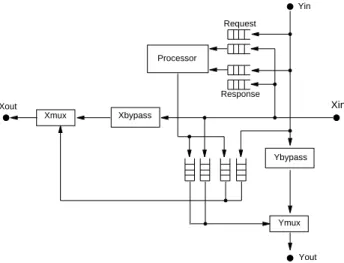
Figure 2 depicts a high-level view of the proposed net-work switch. The switch shown is for a two-dimensional network only, but an extrapolation to higher dimensions is trivial. Only the datapath and queues are shown; the con-trol is not.
The processor interface has one send queue and two receive queues for each dimension. The receive queues are
Processor Bypass buffer Ring in Ring out Stripper Mux
Figure 1. Processor-SCI switch interface
separated into request and response queues, which are treated with different priorities: responses are processed before requests, which helps to prevent deadlocking the network. There are also two additional queues, which function as agent queues connecting the X- and Y-rings. The agent queue organization requires a queue from each ring onto every other ring, which is queues for an n-dimensional network. Including the send and receive queues, this switch organization requires total queues. For higher dimensions this is clearly prohibitively expensive, but the control is much simpler than for merg-ing multiple physical queues. Such a merger would require allowing multiple high-speed channels to simultaneously write variable-sized packets into a single queue.
A previous study [12] assumed that packets sent from a queue were placed into an active buffer to await the return-ing echo. The queues assumed here hold a sent packet in the queue while its transmission is pending. This makes the queue into more of an associative memory than a FIFO structure, but has the advantage of permitting more pack-ets to be queued (should the area taken by the active buffer be reclaimed as queue slots).
When a processor attempts to send a packet, it is placed in the first dimension (lowest or highest, depending on the packet type) in which the packet has any distance to travel. If the send queue for that dimension is full, the processor will block until a slot becomes available. Such a slot is freed only upon the return of an accept echo for a packet saved in that particular queue. Other queues that are full (agent and receive queues) merely generate reject echoes and subsequent retransmissions.
The SCI standard defines several features that have not been accounted for in the simulator. The most significant is the flow control mechanism, which consists of go bits. A node accumulates go bits during its recovery phase to throttle other nodes, so that it is never starved for
band-n2–n
n2+2n
width when ring utilization is high. For a detailed descrip-tion of the flow control algorithm the reader is referred to the standard document [14]. The elasticity buffer, which nodes use to maintain synchronism with adjacent channels (clocks are synchronized with a phase-lock loop), is also not represented in the simulator.
4 Implementation of network simulation
In this section we first describe the original WWT net-work model. We then discuss the changes required to WWT for the centralized SCI simulator, and finally we present the actual simulation algorithm.
4.1 Original WWT network implementation WWT uses a conservative, discrete-event algorithm to simulate execution and the memory hierarchy. The assumed target communication paradigm is hardware-based, cache-coherent shared memory. Using the original constant latency model, remote messages take a parame-terized constant number of cycles to cross the network. The length of the execution quanta is set to be the same as the network latency, guaranteeing that a synchronization point would occur between the virtual time a target mes-sage was sent and the virtual time at which it needed to be scheduled.
Communication on the CM-5 occurs with messages of five words. WWT sends messages broken up into such units, which consist of one header unit followed by data units (where is the size of the message, in words of data). When all units are received, the recipient schedules the target message at virtual time , where is the virtual time at which the message was sent, and is the constant latency across the target network. Since the CM-5 network makes no guarantee of maximum deliv-ery time, a global barrier is performed after each cycles of target execution. This barrier continually performs sum reductions on the number of outstanding messages until the entire network is drained and all target messages slated to be received in the next quantum have been scheduled. Figure 3 illustrates this model.
4.2 Centralized network simulator
The SCI network simulator is incorporated into this communication model as follows. The data units of a CM-5 message are still sent to the destination node, as described in Section 4.1. The header unit, however, is sent to one specific node designated as the network simulator node. This node receives the header, and schedules an event representing the injection of the message into the simulated network.
At the end of a quantum, a global reduction is per-n 4⁄ n n 4⁄ +1 T+nl T nl nl
Figure 2. Datapath of simulated network switch Xout Xbypass Processor Request Response Yin Xin Ybypass Ymux Yout Xmux
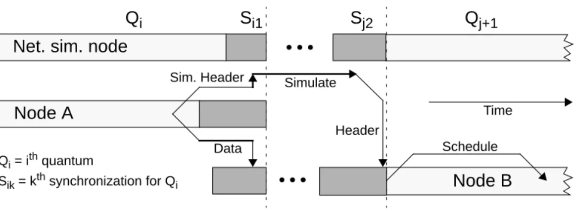
formed to drain the network, assuring that all data units have been received by the destination nodes and that all headers have been received by the network simulator node. The network simulation is then performed for the previously completed quantum. The network simulator identifies any target packets that will be received in the next quantum, and forwards their headers to the original message destinations. Another global reduction is then performed, to assure that all such “completion headers” have been received and the target packet receipts sched-uled. Figure 4 illustrates both the sending of a packet in quantum , and the packet receipt and scheduling immedi-ately before quantum .
Even without the actual network simulation execution, the overall simulation speed suffers under this model, due to the necessarily reduced quantum latency and the extra barrier reduction in between quanta. The quantum latency must be no greater than the difference between the virtual times at which the message receipt time can be calculated and at which the message is completely received (it is set to 24 cycles for the SCI network simulator). This is neces-sary to preserve causality, as with the constant latency model. If the quantum latency is too large, the network simulator may not send the header unit to the intended recipient before the target receipt event was to occur, caus-ing an error. Smaller quanta can greatly inflate simulation
i
j+1
time, as the number of inter-quanta synchronizations per target cycle increases [1].
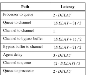
4.3 Resource latencies
The physical times that symbols take to move across network resources are listed in Table 1. is a base factor that accounts for the speed of the hardware. The relations shown in Table 1 were arrived at by estimating the amount of hardware needed to perform each function, and normalizing all latencies to . In the study for which this simulator was first used [7], was set to be 9 cycles.
These delays, however, are measured in network cycles. As the network is not necessarily clocked at the same rate as the processor, a scaling factor was introduced that adjusts network latencies to be converted to the num-ber of instructions issued in the same amount of time. In a previous study [7], we introduced two scaling factors. The first assumed current technology; a network clocked at 250 MHz and a processor (sustaining one IPC) clocked at 200 MHz, resulting in a ratio of 1.2 instructions issued per network cycle. The second assumed technology available in the near future; specifically, a 250 MHz network (that utilizes both edges of the clock for transmission) and a 500 MHz processor, sustaining 2 IPC. The future technological assumptions result in a ratio of 2 instructions issued per
DELAY DELAY DELAY
Q
iS
iQ
i+1Node A
Node B
Qi = ith quantum Si = ith synchronization ql = quantum lengtht
t+ql
Scheduling of message receipt
A target message logically sent from node A to node B at logical time t is scheduled as a receipt event at logical time t+ql.
Time
Figure 3. Original WWT message model
Q
iS
i1S
j2Q
j+1Net. sim. node
Node A
Node B
Time Sim. Header SimulateData
Header
Schedule Qi = ith quantum
Sik = kth synchronization for Qi
network cycle.
4.4 SCI simulation algorithm
Although all of the network simulation is performed at one centralized node (PNS), management of the send queues is performed locally at each node to minimize communication between the sending node and PNS. When a send queue for a given dimension is full, and the pro-cessing element attempts to send another packet beginning in that same dimension, the packet information is saved in a special structure. The sending sequence is then put to sleep, and is reawakened when a send queue slot becomes available. When a buffered message is cleared due to receipt of an accept echo, PNS sends a
free_send_slot message to the sending node, prompting it to check for any sleeping threads that require the sending of a message. Conversely, receive queue buffer management is performed at PNS. Whenever a mes-sage is completely consumed by the receiver, a
free_receive_slot message is sent to PNS, causing it to decrement the queue counter and free the associated storage. This organization allows both sending nodes and PNS to avoid communication whenever checking for a full queue, sending a one-way message only upon the freeing of a queue slot.
Enumerated below are the event types that drive the simulator and the actions taken therein.
• New_Msg: Initializes the packet structure, and places the packet in the send queue. If the bypass buffer is not in recovery mode, it schedules an
Acquire_Channel event for the outgoing channel in the appropriate dimension.
• Acquire_Channel: This event schedules an
Incoming_Message event for the input port of the next node in the ring, schedules a
Relinquish_Channel event for the output port
of the current node, and updates the bypass buffer length.
• Relinquish_Channel: Frees the outgoing chan-nel and checks the bypass buffer and send queue, respectively, to find if anAcquire_Channel event needs to be scheduled.
• Incoming_Message: Acts as the stripper and con-trol specified in the SCI standard. This event deter-mines whether to queue an arriving packet in the bypass buffer or to schedule anAcquire_Channel
event for the outgoing link (if the bypass buffer is empty). If the destination node for the packet’s cur-rent dimension is the receiving node, the packet is either discarded or placed in a queue. An accept echo is scheduled if a slot is available in the appropriate agent or receive queue, and a reject echo is scheduled if that queue is full.
• Fill_Buffer: Simulates decoding, queueing, and transfer delays. Other events, when moving a packet across a structure (such as an agent) schedule a
Fill_Buffer for some time in the future, at which point the packet is actually placed in the queue. The bypass buffer, receive and agent queues, and the resending of a rejected packet all use this event to trigger the appropriate action (usually an
Acquire_Channel event).
• Pullout: Removes a message from a queue after a parameterized delay. This event also frees the mes-sage structure if all related echoes have completed.
5 Experimental results
This section evaluates the necessity, utility, and cost of using the centralized simulator instead of a less-expensive network model. We first measure the error introduced by WWT’s constant 100 cycle network latency and then eval-uate a more accurate constant model. We explore three network design parameters, and finally measure the per-formance of WWT using the SCI network simulator instead of a constant network latency model.
All experimental results presented in this section were obtained by running Ocean, one of the SPLASH [13] benchmarks, as the target application. Ocean is a hydrody-namic simulation, which was run for a 98x98 input grid over two simulated days. All of our experiments used the base SCI coherence protocol with MCS locks [9], 64-byte cache blocks, 32 processors, and asynchro-nous flushes [7]. Unless otherwise specified, simulated networks have 4 slots per queue, and the speed of the net-work switch is cycles.
5.1 Network effect on execution time
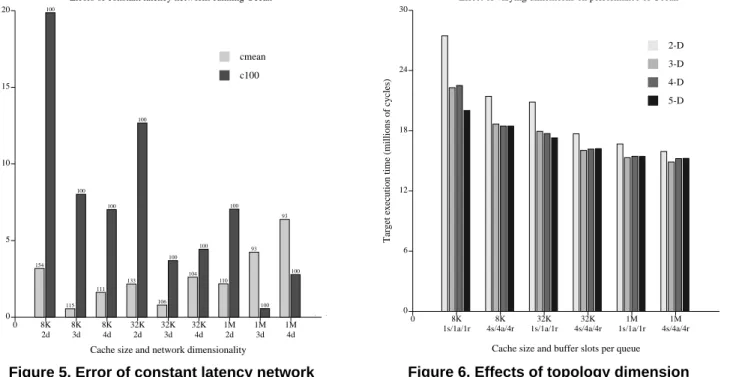
Figure 5 depicts the percent error of constant network DELAY = 9
Path Latency
Processor to queue
Table 1: Latencies through the network
Queue to channel
Channel to channel
Channel to bypass buffer
Bypass buffer to channel
Agent delay Channel to queue Queue to processor 2 DELAY⋅ DELAY–3 ( ) ⁄3 1 DELAY+1 ( ) ⁄2 DELAY–2 ( ) ⁄2 3 DELAY⋅ 2 DELAY⋅ ( ) ⁄3 2 DELAY⋅
latency experiments versus the same experiments using SCI network simulation (henceforth calledns). Two sets of constant latency experiments were run. The first assumed a constant latency of 100 cycles for each set of parameters (we call this modelc100). The second experi-ment set, calledcmean, ranns for each set of parameters, and then reran the simulation using the mean network latency obtained from thens run as the constant network latency.
We varied both the size of each processor cache (using 8KB, 32KB, and 1MB caches) and the number of dimen-sions in which the network was wired.
The errors were calculated using the virtual times (VTs) of the pertinent runs. Each error was calculated as follows: (1) Figure 5 shows errors as high as 20% for c100, but errors up to only 6% for cmean. The constant models consistently underestimatens, since they do not account for contention. The exceptions for which
were the 8KB- and 32KB-cache, two dimension runs of
cmean, which had the two highest mean latencies (154 and 133 cycles respectively). Adjusting the constant laten-cies upward to prevent consistent underestimation of the true execution time would be fruitless, since the range of errors is so large.
The cmean model generates increasingly large posi-tive errors as the number of dimensions increases. This is
Err abs VT( SCI–VTconst) VTSCI
---×100% =
VTconst>VTSCI
counterintuitive, as contention in the network decreases with increasing dimension. We hypothesize that this is caused by increased interference at agent queues, generat-ing greater numbers of message rejections. This would create localized hot-spots in the network that degrade per-formance at a higher proportion than their contribution to overall contention.
The magnitude of the errors, however, is still suffi-ciently small to warrant confidence in cmean. Even though a preliminary run usingns needs to be performed to obtain a rough estimate of the network latency for a class of experiments, usingcmean instead ofc100 per-mits much greater confidence in the simulation results. 5.2 Exploration of network parameters
The SCI network module is useful for exploring the design space of SCI networks. Both the large-scale topol-ogy and the individual switch parameters may be varied and tested through simulation, using genuine parallel pro-gram workloads.
5.2.1 Topology - dimensionality
Increasing the dimensionality of an SCI-based k-ary n-cube network presents an interesting set of trade-offs. A higher number of dimensions increases the total network bandwidth, reducing overall contention. The mean path length per message is also reduced as the number of dimensions grows. A greater dimension-switching latency is incurred in an SCI network than in a more traditional k-ary n-cube network, however, due to buffering overhead
Figure 5. Error of constant latency network
0 5 10 15 20 0 8K 2d 8K 3d 8K 4d 32K 2d 32K 3d 32K 4d 1M 2d 1M 3d 1M 4d
Cache size and network dimensionality
Error (% different in virtual time)
Errors of constant latency networks running Ocean
154 100 115 100 111 100 133 100 106 100 104 100 110 100 93 100 93 100 . . cmean c100
Figure 6. Effects of topology dimension
0 6 12 18 24 30 0 8K 1s/1a/1r 8K 4s/4a/4r 32K 1s/1a/1r 32K 4s/4a/4r 1M 1s/1a/1r 1M 4s/4a/4r
Cache size and buffer slots per queue
Target execution time (millions of cycles)
Effect of varying dimensions on performance of Ocean
2-D 3-D 4-D 5-D
and the delays of traversing the agent.
Figure 6 depicts the performance effects of varying the number of dimensions in the network. We selected values of that would maximize performance: balanced powers of two (i.e., a 3-dimensional 32-node network would have the dimensions 4x4x2). The execution time for Ocean is plotted against 6 cluster bargraphs, which vary processor cache size and buffer space in the network. The notation “xs/ya/zr” represents x buffer slots in each send queue, y slots per agent queue, and z slots per receive queue.
The effects of the parameters on network utilization are straightforward: smaller cache sizes will tend to increase the load on the network, as will fewer agent and receive queue slots (fewer send slots, conversely, will decrease the network utilization but will still increase the total execu-tion time).
The results in Figure 6 show, unsurprisingly, that a 2-dimensional network performs worse than one with higher dimensionality, particularly when the network utilization is higher. Contention becomes less of a problem when the network is more lightly loaded, causing the performance of 2-dimensional networks to approach that of higher-dimension networks.
Three-dimensional networks perform almost as well as higher numbers of dimensions when the network load is high (i.e., for the 8KB-cache experiments). For the 1MB-cache experiments, the three-dimensional network actu-ally performs better than higher dimension networks. This is because the network traffic is sparse enough that the higher-dimension networks do not significantly reduce
k
contention. They also do not greatly reduce path length (for 32 nodes, which is a small system for a 4- or 5-dimen-sional network). The high-dimension networks do, how-ever, cause messages to switch rings more frequently, incurring the latency of moving through multiple agents. This degradation subsumes the slight performance gains obtained by reducing contention and path length, causing total execution time to increase.
Increasing the number of target nodes should not quali-tatively affect these results; we expect that the optimal point will merely shift to a higher number of dimensions as the number of target nodes is progressively increased.
5.2.2 Queue sizes
Queues are quite expensive in terms of real-estate, par-ticularly when holding something as large as an SCI data message (80 bytes). Minimizing the size of the queues without sacrificing too much system performance is an important goal. We have therefore measured the perfor-mance effects of constraining the network queue sizes.
Real queues would likely be designed to hold a certain quantity of data, and would be able to buffer as many mes-sages as could fit in that quantity. For simplicity, we ignored this fact and assumed queues that could hold only a certain number of packets, not a certain quantity of data. This will make our results somewhat pessimistic.
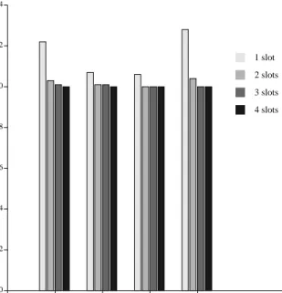
Figure 7 shows the slowdowns associated with con-straining the sizes of various queues in the network. The three classes of queues are send queues, agent queues, and receive queues (recall that a receive queue is actually two
Figure 7. Number of slots per queue
0.0 0.2 0.4 0.6 0.8 1.0 1.2 1.4
0 Send Agent Receive All
Which queues are limited
Ratio of run-time to 10x10x10 queue slots run-time
Effect of changing queue sizes for Ocean, 8K cache
1 slot 2 slots 3 slots 4 slots
Figure 8. Network switch speed
0 3 6 9 12 15 18 21 24 27 0 8K 2d 8K 3d 8K 4d 32K 2d 32K 3d 32K 4d 1M 2d 1M 3d 1M 4d
Cache size and topology dimension
Target execution time (millions of cycles)
Effect of network speed on performance of Ocean
4 cycles 9 cycles 14 cycles
queues, one each for requests and responses, and thus has double the number of specified slots). We measured the execution of Ocean (assuming a 2-D, 32 node network with an 8K processor cache, to maximize contention) for a range of queue sizes.
Each cluster in Figure 7 constrains one type of queue to either 1, 2, 3, or 4 slots, and assumes 4 slots in the other two queue types. The last cluster constrains all queue types to 1, 2, 3, and 4 slots. The execution times of these experiments were normalized to an execution assuming 10 slots in each type of queue, which for our workloads was effectively infinite.
The results show virtually no benefit of implementing more than two slots in any type of queue. Agent and receive queues show a small benefit from having two slots instead of one. Execution time is improved by over 15% when the send queue has two slots rather than one. We hypothesize that this is primarily due to responses being blocked in the processing element, which degrades perfor-mance faster than simply slowing the flow of requests into the network.
5.2.3 Switching speeds
Figure 8 graphs the effects of varying the network switch speed. (Altering the network clock in the simula-tion is one way to accomplish this). We present the target execution time on the y-axis, in millions of target cycles. On the x-axis are clusters, one for each experiment, vary-ing processor cache size and interconnect dimensionality. The intra-cluster bars each represent a different base value
for the speed of the network switch. This value is equiva-lent to the parameter presented in Table 1. The three values used for are 4, 9, and 14.
The results of these experiments show that faster or slower switches do not qualitatively affect relative execu-tion times when cache sizes or dimensionality are altered. The target execution times are scaled by a roughly linear factor as is raised or lowered. The lack of severe performance degradation due to slow switches is primarily due to the flow control imposed by the SCI transport layer; this prevents network occupancy from skyrocketing as the switches become slower relative to the processors.
An interesting side-effect of faster ( ) switches is that the slight performance degradation at higher dimensions disappears, as the relative overhead of switching rings through an agent diminishes.
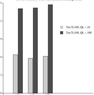
5.3 Simulator performance
Figure 9 quantifies the slowdowns incurred by running the SCI network simulator. The three clusters represent a range of network utilizations.
The dark grey bars show the slowdown ofns over the
c100 model, with the quantum latency for c100 set at 100 cycles. These slowdowns are reasonably stable across increasing network load, and vary between 14 and 15.
The lighter grey bars also represent the slowdown of
ns versusc100, but with a quantum latency of 24 cycles for c100. These bars thus depict the slowdowns due solely to the increased computation for ns (a factor of about 6). The differences between the two sets of bars quantify the additional slowdowns due to the necessary disparity in quanta size (sincens must be run with a quan-tum length of 24 cycles). This difference is roughly a fac-tor of 2.5, with or without network simulation.
6 Summary
Parallel simulation has become an extremely important technique for evaluating future systems. The Wisconsin Wind Tunnel is one such simulator, which enables effi-cient simulation of large parallel machines.
Unfortunately, simulating an interconnection network at any level of detail drastically reduces the simulation efficiency. Ignoring the network for the sake of speed, however, can lead to large errors and erroneous conclu-sions.
In this paper we described an extension to WWT that accurately simulates the Scalable Coherent Interface trans-port layer and network. When coupled with the SCI cache-coherence module that runs on WWT, a complete SCI sys-tem is simulated.
We selected one of the SPLASH benchmarks—one that generates a higher load on the network than most of the
DELAY
DELAY
DELAY
DELAY = 4
Figure 9. Network simulation slowdown
0 3 6 9 12 15 0 15.5% 24.9% 32.2% Network utilization Slowdown
Slowdown effects of network simulation running Ocean
Tns/Tc100, QL = 24 Tns/Tc100, QL = 100
others—and performed a series of experiments to evaluate the trade-offs and importance of using this simulator. We first demonstrated that the error of the original WWT net-work model can be quite high (~20%), depending on the target network assumptions. We then showed that using our simulator to estimate a mean network latency (for multiple experiments using the faster constant latency model) can significantly reduce error without sacrificing speed.
We also demonstrated the utility of our simulator for evaluating network design parameters: optimal dimension-ality and buffer space in the network switches. We found that, for a 32-node system, three dimensions seems to offer the best cost/performance. We showed that using 2 slots per send, agent, and receive queue captures most of the advantages of queueing. We also showed that varying the speed of the network does not produce any surprising effects (for these experiments); a decrease in switch speed (or an increase in network cycle time) slows the target exe-cution time proportionately.
Finally, we quantified the performance impact of using this simulator, and showed it to be somewhat substantial. The network simulator slows WWT down by roughly a factor of 6, more or less independent of network load. The necessitated reduction in quantum size more than doubles the performance hit of the network simulation, increasing the slowdown to approximately 15.
Although somewhat expensive, we consider this to be an extremely useful tool that will increase our confidence in many of our results and permit us to explore a more sophisticated design space of SCI-based machines.
Acknowledgments
Many thanks go to David Wood, who contributed greatly to the development of the original WWT network simulator, Steve Reinhardt and Babak Falsafi, who pro-vided valuable assistance during the simulator develop-ment, and Alain Kägi, who developed the SCI cache-coherence simulator used in these experiments. Alain and Subbarao Palacharla provided helpful comments that improved this paper. Finally, we wish to thank Dave James and Don North of Apple Computer for their generous sup-port.
References
[1] Douglas C. Burger and David A. Wood. Accuracy vs. Perfor-mance in Parallel Simulation of Interconnection Networks. In
Pro-ceedings of the 9th International Parallel Processing Symposium,
April 1995.
[2] David L. Chaiken and Anant Agarwal. Software-Extended Coher-ent Shared Memory: Performance and Cost. In Proceedings of the
21th Annual International Symposium on Computer Architecture,
pages 314–324, April 1994.
[3] R.C. Covington, S. Madala, V. Mehta, J.R. Jump, and J.B.
Sin-clair. The Rice Parallel Processing Testbed. In Proceedings of the
1988 ACM SIGMETRICS Conference on Measurements and Mod-eling of Computer Systems, pages 4–11, May 1988.
[4] Helen Davis, Stephen R. Goldschmidt, and John Hennessy. Multi-processor Simulation and Tracing Using Tango. In Proceedings of
the 1991 International Conference on Parallel Processing, pages
II99–107, August 1991.
[5] Richard M. Fujimoto. Parallel Discrete Event Simulation.
Com-munications of the ACM, 33(10):30–53, October 1990.
[6] Ross E. Johnson and James R. Goodman. Interconnect Topologies with Point-to-Point Rings. Technical Report 1058, Computer Sci-ences Department, University of Wisconsin-Madison, September 1991.
[7] Alain Kägi, Nagi Aboulenein, Douglas C. Burger, and James R. Goodman. Techniques for Reducing the Overheads of Shared-Memory Multiprocessing. Technical Report 1266, Computer Sci-ences Department, University of Wisconsin-Madison, 1995. [8] Boris D. Lubachevsky. Efficient Distributed Event-Driven
Simu-lations of Multiple-Loop Networks. Communications of the ACM, 32(2):111–123, January 1989.
[9] John M. Mellor-Crummey and Michael L. Scott. Algorithms for Scalable Synchronization on Shared-Memory Multiprocessors.
ACM Transactions on Computer Systems, 9(1):21–65, February
1991.
[10] David Nicol. Conservative Parallel Simulation of Priority Class Queueing Networks. IEEE Transactions on Parallel and
Distrib-uted Systems, 3(3):398–412, May 1992.
[11] Steven K. Reinhardt, Mark D. Hill, James R. Larus, Alvin R. Leb-eck, James C. Lewis, and David A. Wood. The Wisconsin Wind Tunnel: Virtual Prototyping of Parallel Computers. In Proceedings
of the 1993 ACM SIGMETRICS Conference on Measurements and Modeling of Computer Systems, pages 48–60, May 1993.
[12] Steven L. Scott, James R. Goodman, and Mary K. Vernon. Perfor-mance of the SCI Ring. In Proceedings of the 19th Annual
Inter-national Symposium on Computer Architecture, pages 403–414,
May 1992.
[13] Jaswinder Pal Singh, Wolf-Dietrich Weber, and Anoop Gupta. SPLASH: Stanford Parallel Applications for Shared Memory.
Computer Architecture News, 20(1):5–44, March 1992.
[14] IEEE Computer Society. IEEE Standard for Scalable Coherent Interface (SCI). IEEE Std 1596-1992, August 1993.
[15] Jeff S. Steinman. Breathing Time Warp. In Proceedings of