International Journal of Emerging Technology and Advanced Engineering
Website: www.ijetae.com (ISSN 2250-2459, ISO 9001:2008 Certified Journal, Volume 5, Issue 1, January 2015)
413
Performance Evaluation of Space Time Block Codes Using Bit
Error Rate in MIMO Systems
Prof. Keyur U. Chauhan
1, Prof. Bhargav B. Patel
2, Prof. Sagar B. Patel
31,2,3
MBICT College, EC Department, New V.V.Nagar
Abstract— This Multipath fading is inherent in wireless communication systems. Diversity is the technique which takes the advantage of multipath and mitigates the effect of fading and increase received signal strength. Space Time Block codes (STBC) is a promising way to improve the
performance of wireless communication system by
maximizing transmit diversity in space as well as time for flat fading channel using multiple antennas at the transmitter side and multiple antennas at the receiver side which is called as MIMO.
In this paper, we present simulation and comparison of various STBCs with fixed number of transmit and variable number of receive antennas because higher diversity can be
achieved by increasing uncorrelated paths between
transmitter and receivers. Simulation results also show that the comparison of different Scheme of OSTBC for QPSK Modulation and the BER Performance Comparison of Alamouti Scheme in Frequency Selective Channel Using BPSK Modulation. Additionally Simulation results of OSTBC using QPSK and 16QAM Modulation scheme.
Keywords— OSTBC, QPSK, QAM, STC, MIMO.
I. INTRODUCTION
With rapid expansion of the Internet and development of related services, the Internet has become an indispensable part of daily life creating a need for high speed and reliable communication systems. The research community has generated a number of promising solutions for significant improvements in system performance. One of the most
promising future technologies in mobile radio
communications is multi antenna elements at the transmitter and at the receiver.
Multiple-input multiple-output (MIMO) open a new dimension in reliable communication, in which transmit antennas at one end and the receive antennas at the other end are connected and combined‖ in such a way that the quality (the bit error rate (BER), or the data rate) for each user is improved. The core idea in MIMO transmission is space-time signal processing in which signal processing in time is complemented by signal processing in the spatial dimension by using multiple, spatially distributed antennas at both ends.
One inherent problem of the wireless channel is fading, which occurs as the signal follows multiple paths between transmit and receive antennas. Under certain, not uncommon conditions, the arriving signals will add up destructively, reducing the received power to zero (or very near to zero). In this case reliable communication is very difficult.
Fading can be mitigated by diversity, which means that the information is transmitted not only once but several times, hoping that at least one of the replicas will not undergo severe fading. Diversity makes use of an important property of wireless MIMO channels: different signal paths can be often modeled as a number of separate, independent fading channels. These channels can be distinct in frequency domain or in time domain.
Several transmission schemes have been proposed that utilize the MIMO channel in different ways, e.g., spatial multiplexing, space-time coding or beam forming. Space-time coding (STC), introduced first by Tarokh at el. [3], is a promising method for transmit multiple copies of a data stream across a number of antennas in different time slots, so it provides diversity in time as well as in space, so ultimately by using STC we get diversity maximization. These code symbols are generated by the space-time encoder in such a way that diversity gain, coding gain, as well as high spectral efficiency are achieved.
Space-time coding finds its application in IEEE 802.11n standard, i.e. one of the Wi-Fi systems, 3GPP Long Term Evolution (LTE) and the 3GPP2 Ultra Mobile Broadband (UMB) standards.
In the last few years the research community has made an enormous effort to understand space time codes, their performance and their limits. This paper explains the concept of complete family of space time block code in a systematic way. This paper starts with basic MIMO and Space time Block code with method of Alamouti scheme and its generalized form known as OSTBC.
II. BASIC OF MINO
International Journal of Emerging Technology and Advanced Engineering
Website: www.ijetae.com (ISSN 2250-2459, ISO 9001:2008 Certified Journal, Volume 5, Issue 1, January 2015)
414 In particular, at the end of the 1990s multiple-antenna techniques were shown to provide a novel means to achieve both higher bit rates and smaller error rates. In addition to this; multiple antennas can also be utilized in order to mitigate co-channel interference, which is another major source of disruption in (cellular) wireless communication systems. Altogether, multiple-antenna techniques thus constitute a key technology for modern wireless communications.
Fig.1 Benefits of Multiple Antenna Techniques for Wireless Communications [12]
The benefits of multiple antennas for wireless communication systems are summarized in Fig. In the sequence, they are characterized in more detail.
1. Higher Bit Rates with Spatial Multiplexing
2. Smaller Error Rates through Spatial Diversity
3. Improved Signal-to-Noise Ratios and
Co-Channel-Interference Mitigation Using Smart Antennas
4. Combined Techniques.
In contrast to spatial multiplexing techniques, where the main objective is to provide higher bit rates compared to a
single-antenna system, spatial diversity techniques
predominantly aim at an improved error performance. This is accomplished on the basis of a diversity gain and a coding gain. Indirectly, spatial diversity techniques can also be used to enhance bit rates, when employed in conjunction with an adaptive modulation/channel coding scheme.
There are two types of spatial diversity, referred to as macroscopic and microscopic diversity.
III. SPACE TIME BLOCK CODES
The main idea of transmit diversity is to provide a diversity and/or coding gain by sending redundant signals over multiple transmit antennas (in contrast to spatial multiplexing, where independent bit sequences are transmitted). To allow for coherent detection at the receiver, an adequate preprocessing of the signals is performed prior to transmission, typically without channel knowledge at the transmitter. With transmit diversity, multiple antennas are only required at the transmitter side, whereas multiple receive antennas are optional. However, they can be utilized to further improve performance. In cellular networks, for example, the predominant fraction of the overall data traffic typically occurs in the downlink. In order to enhance the crucial downlink it is therefore very attractive to employ transmit diversity techniques, because then multiple antennas are required only at the base station. With regard to cost, size, and weight of mobile terminals this is a major advantage over diversity reception techniques.
An early beginning of transmit diversity schemes was made with two papers that independently proposed a simple technique called delay diversity [8], [9]. Another early publication on transmit diversity can be found, e.g. in [10].
However, the value of transmit diversity was only recognized in 1998, when Alamouti proposed a simple technique for two transmit antennas [2]. In the same year, Tarokh, Seshadri, and Calderbank presented their space-time trellis codes (STTCs) [9], which are two-dimensional coding schemes for systems with multiple transmit antennas. While delay diversity and Alamouti’s transmit diversity scheme provide solely a diversity gain (more precisely, full diversity with regard to the number of transmit and receive antennas), STTCs yield both a diversity gain and an additional coding gain.
International Journal of Emerging Technology and Advanced Engineering
Website: www.ijetae.com (ISSN 2250-2459, ISO 9001:2008 Certified Journal, Volume 5, Issue 1, January 2015)
415 In the delay diversity scheme [8], [9], for example, identical signals are transmitted via the individual antennas, using different delays. This causes artificial ISI, which can be resolved at the receiver by means of standard equalization techniques available for single-antenna systems. In contrast to this, Alamouti’s transmit diversity
scheme [2] performs an orthogonal space-time
transmission, which allows for ML detection at the receiver by means of simple linear processing.
Fig.2. Basic Principle of Space Time Coding
STTCs [10] may be interpreted as generalizations of trellis coded modulation to multiple transmit antennas. Optimum decoding in the sense of MLSE can be performed using the Viterbi algorithm. On the basis of simulation results, it was shown in [10] that STTCs offer an excellent performance that is within 2-3 dB of the outage capacity limit. However, this performance comes at the expense of a comparatively high decoding complexity. Motivated by the simple receiver structure of [2], orthogonal space-time block codes (OSTBCs) were introduced in [10], which constitute a generalization of Alamouti’s scheme to more than two transmit antennas. OSTBCs are designed to achieve full diversity with regard to the number of transmit and receive antennas. In contrast to STTCs, OSTBCs do not offer any additional coding gain.
IV. ORTHOGONAL SPACE BLOCK CODE
This chapter discusses about the orthogonal STBC which has the characteristics of providing full rate and full diversity for two transmit antennas and for more than two transmit antennas it provides full diversity with less than one transmission rate. STBC are basically design for flat fading channel this chapter also provides the concept of using OSTBC in frequency selective channel using OFDM.
Chapter starts with the theory concept of OSTBC in flat as well as in frequency selective channel and concluded with simulation results and observations.
A. Alamouti Scheme
In addressing the challenge of decoding complexity, a remarkable scheme for two transmit antenna MIMO system is proposed [5], which is widely referred to as the Alamouti scheme. Properties of Alamouti schemes are full rate and full diversity but it is limited to two transmit antennas.
1. Signal transmission of Alamouti code
A block diagram of the Alamouti space time encoder is shown in Figure. The information bits are first modulated using an M-ary modulation scheme. The encoder takes the
block of two modulated symbols and in each
encoding operation and hands it to the transmit antennas according to the code matrix shown in eq. (4.1)
Fig.3 Block Diagram of the Alamouti Space-Time Encoder
The first row represents the first transmission period and the second row the second transmission period. During first
transmission, symbols and are transmitted
simultaneously from antenna one and antenna two respectively. In the second transmission period, the symbol
is transmitted from antenna one and the symbol from transmit antenna two. It is clear that the encoding is performed in both time (two transmission intervals) and space domain (across two transmit antennas). The two rows and columns of C are orthogonal to each other and the code matrix in eq. is orthogonal:
CCH =
=
International Journal of Emerging Technology and Advanced Engineering
Website: www.ijetae.com (ISSN 2250-2459, ISO 9001:2008 Certified Journal, Volume 5, Issue 1, January 2015)
416
Where I2 is a (2 × 2) identity matrix. This property
enables the receiver to detect and by a simple linear
signal processing operation.
2. Signal reception of Alamouti code
Let us look at the receiver side now. A block diagram of the Alamouti space-time decoder is shown in Fig. 4.2. Only one receive antenna is assumed to be available. The channel at time t may be modeled by a complex
multiplicative distortion h1(t) for transmit antenna one and
h2(t) for transmit antenna two.
Fig.4 Block Diagram of the Alamouti Space-Time Decoder
Assuming that the fading is constant across two consecutive transmit periods of duration T, we can write
h1(t) = h1(t+T) = h1 = | h1|
h2(t) = h2(t+T) = h1 = | h2|
Where, |hj| and j , j = 1, 2 are the amplitude gain and
phase shift for the path from transmit antenna j to the receive antenna. The received signals at the time t and t + T can then be expressed as
r1 = h1 + h2 + n1
r2 = h1 + h2 + n2
Where, r1 and r2 are the received signals at time t and t +
T, n1 and n2 are complex random variables representing
receiver noise and interference. This can be written in matrix form as:
r = Ch + n
Where, h = [h1, h2] T is the complex channel vector and n
is the noise vector at the receiver.
V. LINEAR SIGNAL COMBINING AND MAXIMUM
LIKELIHOOD DECODING OF THE ALAMOUTI CODE
If the channel coefficients h1 and h2 can be perfectly
estimated at the receiver, the decoder can use them as channel state information (CSI).
Assuming that all the signals in the modulation constellation are equiprobable, a maximum likelihood
(ML) detector decides for that pair of signals ( , )
from the signal modulation constellation that minimizes the decision metric
d2 (r1, h1 + h2) + d2 (r2, h1 + h2) =
| r1 - h1 - h2|2 + | r2 + h1 - h2|2
Where, d(x1, x2) = |x1 - x2|. On the other hand, using a linear receiver, the signal combiner at the receiver
combines the received signals r1 and r2 as follows
Hence and are two decisions statistics constructed
by combining the received signals with coefficients derived from the channel state information. These noisy signals are sent to ML detectors and thus the ML decoding rule can be
separated into two independent decoding rules for and
namely For detecting
For detecting
The Alamouti transmission scheme is a simple transmit diversity scheme which improves the signal quality at the receiver using a simple signal processing algorithm (STC) at the transmitter. The diversity order obtained is equal to that one applying maximal ratio combining (MRC) with one antenna at the transmitter and two antennas at the receiver where the resulting signals at the receiver are:
r1 = h1 + n1
r2 = h2 + n2
and the combined signal is
= r1 + r2
International Journal of Emerging Technology and Advanced Engineering
Website: www.ijetae.com (ISSN 2250-2459, ISO 9001:2008 Certified Journal, Volume 5, Issue 1, January 2015)
417 The resulting combined signals in are equivalent to those obtained from a two-branch MRC in equ. The only difference is phase rotations on the noise components which do not degrade the effective SNR. Therefore, the resulting diversity order obtained by the Alamouti scheme with one receiver is equal to that of a two-branch MRC at the receiver. We confirm this statement by simulating the BER performance of the Alamouti scheme.
VI. ORTHOGONAL SPACE-TIME BLOCK CODES(OSTBCS) IN FLAT FADING CHANNEL
The pioneering work of Alamouti has been bases to create OSTBCs for more than two transmit antennas [6], [7]. Orthogonal STBCs are an important subclass of linear STBCs that guarantee that the ML detection of different
symbols {Cn} is decoupled and at the same time the
transmission scheme achieves a diversity order equal
to . The main disadvantage of OSTBCs is the facts
that for more than two transmit antennas and complex-valued signals; OSTBCs only exist for code rates smaller than one symbol per time slot.
Next, we will give a general survey on orthogonal design and various properties of OSTBCs. There exist real orthogonal and complex orthogonal designs. We focus here on complex orthogonal designs. More about real orthogonal design can be found in [6], [8]. In this thesis we consider four transmit and multiple receive antennas for different types of modulation schemes and observe the BER performance.
An OSTBC is a linear space-time block code C that has the following unitary property:
CHC= 2 I
According to eq. the columns of the transmission matrix C are orthogonal to each other. That means that in each block, signal sequences from any two transmit antennas are orthogonal. The orthogonality enables us to achieve full transmit diversity and at the same time, it allows the receiver by means of simple MRC to decouple the signals transmitted from different antennas and consequently, it allows a simple ML decoding.
Next, we will show some OSTBC matrices for NT = 3
and 4 antennas. For NT = 2 transmit antennas the most
popular OSTBC is the Alamouti code eq.
a. OSTBC with a rate of ½ symbols per time slot
For any arbitrary complex signal constellation, there are OSTBCs that can achieve a rate of 1/2 for any given
number of Nt transmit antennas.
For example, the code matrices C3 and C4 are OSTBCs for three and four transmit antennas, respectively and they have the rate ½[13].
With the code matrix C3, four complex symbols are taken at a time and transmitted via three transmit antennas in eight time slots. Thus, the symbol rate is ½. With the code matrix C4, four symbols are taken at a time and transmitted via four transmit antennas in eight time slots, resulting in a transmission rate of 1/2 as well.
b. OSTBC with a rate of ¾
The following code matrices and are complex
[image:5.612.327.567.387.528.2]generalized designs for OSTBC with rate 3/4 for three and four transmit antennas, respectively [10] Obviously, some transmitted signal samples are scaled linear combinations of the original symbols. for simulation purpose four transmit and variable receive antennas are consider. Code matrix defined in eq. (4.12) is used for simulation process. Figure shows the OSTBC encoder and decoder part is describe in figure 4.6
[image:5.612.326.559.391.689.2]Fig.5 Block Diagram of OSTBC Encoder
[image:5.612.337.553.559.693.2]International Journal of Emerging Technology and Advanced Engineering
Website: www.ijetae.com (ISSN 2250-2459, ISO 9001:2008 Certified Journal, Volume 5, Issue 1, January 2015)
[image:6.612.57.279.147.281.2]418 Fig.7 Four Transmit and Two Receive Antennas, Showing the Fading
Channel Coefficients
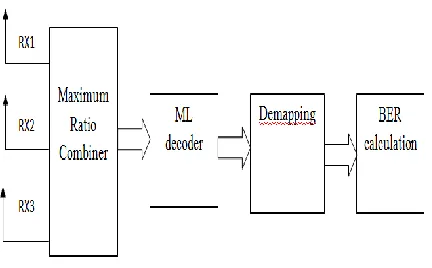
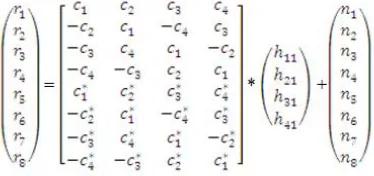
[image:6.612.328.566.194.373.2]As shown in figure OSTBC encoder first input symbols modulated, in this simulation QPSK and 16-QAM modulation scheme are consider. Then modulated symbols are applied to OSTBC convertor. From here symbols are encoded in space and time as shown equation. As shown in Figure four symbols are transmitted in eight time slot from four transmit antennas. Received symbol matrix for four transmit and single receive antennas is shown in equation, this equation can be generalized for four transmit and three receive antennas. At the receiver side combiner will combine the signals transmitted from four transmit antennas and receive at particular receive antennas. After this process ML decoder will decode the symbols
( )[9]. Demapping gives demodulated
symbols i.e. information symbols and finally BER is calculated.
VII. SIMULATION RESULTS
a. The BER Performance Comparison of BPSK with
MRRC and Two-Branch Transmit Diversity in Flat Fading Channel.
Fig. shows that the performance of the Alamouti (2x1) is 2dB worse than two-branch MRRC. 2dB penalty is incurred because the simulations assume that each transmit antenna radiates half the energy in order to ensure the same total radiated power as with one transmit antenna. If each transmit antenna in the new scheme was to radiate the same energy as the single transmit antenna for MRRC, however, the performance would be identical [2].
The (2× 2) Alamouti scheme shows a better performance than either of the other curves because the order of
diversity in this case is = 4. In general, the
Alamouti scheme with two transmit and Nr receive antennas has the same diversity gain as an MRC receive diversity scheme with one transmit and 2Nr receive antennas.
The BER Performance Comparison of Alamouti
[image:6.612.79.266.519.607.2]International Journal of Emerging Technology and Advanced Engineering
Website: www.ijetae.com (ISSN 2250-2459, ISO 9001:2008 Certified Journal, Volume 5, Issue 1, January 2015)
[image:7.612.333.568.125.376.2] [image:7.612.62.272.148.319.2]419 Fig. shows performance of Alamouti schemes (2x1 and 2x2) with different level of modulation. From this figures it is noted that when diversity order becoming double there is 3dB performance gain is achieved and this gain is independent of modulation scheme
Table-1
Comparisons of Alamouti Scheme and MRC for BPSK
When diversity order becoming double there is 3dB
improving in performance at higher SNR the performance gap between 2x1 and 2x2 scheme is becoming slightly wider which shows that at higher SNR the improvement in performance is slightly increase performance gain which is achieved because of diversity is independent of modulation scheme i.e. there 3db performance gain as we shifted from 2x1 to 2x2, this gain is applicable for all modulation schemes.
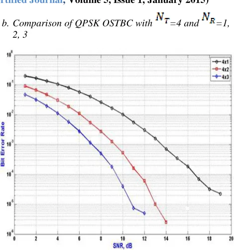
b. Comparison of QPSK OSTBC with =4 and =1,
2, 3
As the numbers of uncorrelated paths are increasing the diversity order is also increasing because of this there should be improvement in BER.
Fig. shows the simulation results of OSTBC using four transmit antennas and variable receive antennas. It is noted from the figure that when 4x1 OSTBC used we get 13.5dB
SNR at 10-3 BER, at the same BER we get 9dB SNR when
we go for 4x2 schemes, as diversity order is becoming double when we are shifted from 4x1 to 4x 2 schemes. It can be observed from the Fig. 4.12 that there is 6dB performance improvement when 4x3 OSTBC is used
International Journal of Emerging Technology and Advanced Engineering
Website: www.ijetae.com (ISSN 2250-2459, ISO 9001:2008 Certified Journal, Volume 5, Issue 1, January 2015)
420
c. Comparison of 16-QAM OSTBC with =4 and
=1, 2, 3
Fig. shows the simulation results of OSTBC using four transmit and multiple receive antennas for QAM. 16-QAM modulation scheme is higher compared with QPSK because of this reason we get high spectral efficiency but with sacrificing in performance. We can see the same observations for diversity order i.e. as we go for higher number of receive antennas number of uncorrelated paths are increased and because of this improvement in BER with reference to number of receive antennas (i.e. there is same
6dB improvement in SNR for BER=10-3 when we are
shifted from 4x1 to 4x3) for 16-QAM and QPSK.
This simulations are limited to three receive antennas because at four transmit and three receive antennas we get very lower value of SNR. This lower value of SNR is easily preferable. But in general we can increase number of receive antennas up to eight without any performance loss but little scarifying in complexity at the receiver.
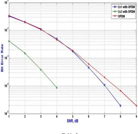
[image:8.612.59.277.137.382.2] [image:8.612.329.556.145.366.2]d. The BER Performance Comparison of Alamouti Scheme in Frequency Selective Channel Using BPSK Modulation
Table-2
Comparison of Different Scheme of OSTBC for QPSK Modulation
OSTBC Provides 4dB improvement when diversity
order becoming double at target BER of 10-4 for QPSK
and 16QAM both so we can say that diversity gain is independent of modulation scheme From the above table it
is noted that at BER of 10-3 we get diversity gain of 3.3 dB
which is increases to 4dB at BER of 10-4 because diversity
International Journal of Emerging Technology and Advanced Engineering
Website: www.ijetae.com (ISSN 2250-2459, ISO 9001:2008 Certified Journal, Volume 5, Issue 1, January 2015)
421
VIII. CONCLUSIONS
This paper is based on space-time coding for multiple- input/multiple-output (MIMO) systems in flat fading as well as in frequency selective channel. Initially, create the base of STBC by describing the concept of space-time coding in a systematic way. Afterwards the paper includes theory and simulation results of BER Performance of OSTBC.
1)BER Performance of MIMO-OFDM with Alamouti
for different modulation techniques.
2)Performance improvement obtained for
MIMO-OFDM as compared to only MIMO-OFDM increases with level of modulation. Thus diversity plays important role for higher level modulation techniques like 64-QAM.
3)Diversity gain obtained when we move from 2x1
Alamouti to 2x2 Alamouti is 3dB and independent of modulation schemes for flat fading as well as for frequency selective channel.
This paper involves the studying of 802.11n WLAN through simulations by considering the physical layer parameters like different coding schemes, various modulation techniques and different types of STBC. The performance is measured in the form of bit error rate (BER).
REFERENCES
[1] G. J. Foschini, ―Layered space-time architecture for wireless communication in a fading environment when using multi-element antennas,‖ ell Syst. Tech. J., pp. 41–59, Autumn 1996.
[2] S. Alamouti, ―A Simple Transmitter Diversity Technique for Wireless communications‖, IEEE Journal on Selected Areas of Communications, Special Issue on Signal Processing for Wireless Communications, vol.16, no.8, pp.1451-1458, Oct.1998.
[3] D. G. Brennan, ―Linear diversity combining techniques,‖ Proc. IRE,vol. 47,pp.1075–1102, June 1959, Reprint: Proc. IEEE, vol. 91, no. 2, pp. 331-356, Feb. 2003.
[4] L.C.Godara, ―Application of antenna arrays to mobile communications –Part: Performance improvement, feasibility, and system considerations; PartII: Beam-forming and direction-of-arrival considerations,‖ Proc. IEEE,vol.85,no.7/8,pp.1031–1060, 1195– 1245, July/Aug. 1997.
[5] L. Zheng and D.N.C. Tse, ―Diversity and multiplexing: A fundamental trade-offs in multiple-antenna channels,‖ IEEE Trans. Inform. Theory, vol.49,no.5,pp.1073–1096, May 2003
[6] G.D.Gray, ―The simulcasting technique: An approach to total-area radio coverage,‖IEEE Trans. Veh. Technol., vol. VT-28, no. 2, pp. 117–125, May 1979.
[7] P. Balaban and J. Salz, ―Optimum diversity combining and equalization in digital data transmission with applications to cellular mobile radio – Part I: Theoretical considerations; PartII: Numericalresults, IEEETrans.Commun‖ vol.40, no.5, pp.885–894, 895–907, May 1992.
[8] N. Seshadri and J. H. Winters, ―Two signaling schemes for improving the error performance of frequency-division-duplex (FDD) transmission systems using transmitter antenna diversity,‖ in Proc. IEEE Veh.Technol. Conf. (VTC), Secaucus, New Jersey, USA, May 1993, pp.508–511.
[9] M. DaSilva and E. S. Sousa, ―Fading-resistant modulation using several transmitter antennas,‖IEEE Tans. Commun. Vol.45,no.10, pp. 1236-1244, Oct. 1997.
[10] J. G. Proakis, Digital Communications, 4th ed. New York, NY: McGraw-Hill, 2001