280
Comparative Performance Analysis of Induction Motor Using
Semiconductor Devices in Terms of Firing Angle
Umar Farooq Siddiqui
1, Ajit Verma
2, Shilpa Soni
3Abstract—Due to harmonics, sudden voltage dips and large fluctuating torque causes a great problem in the starting of large induction motor. Some times due to tripping of relay, equipment failure, surge, no load or overload motor voltage fluctuates resulting in the failure of motor starting. This paper discusses the solution of these problems by using soft starter technique. Soft starting of induction motor is obtained by using power switching devices. In this paper THD is calculated by various firing angles, and influence of load variations in terms of firing angle has been investigated for Thyristor and IGBT (Insulated Gate Bipolar Transistor).
Keywords—Variable speed induction motor, Soft Starter, Thyristor, IGBT, Firing Angle, THD.
I. INTRODUCTION
Harmonic is component of a sine wave that is an integer multiple of the fundamental wave. Harmonics cause losses and depreciation in the transmission and distribution equipment and power consumers, so to control them is essential. One method is to insert filter between the supply and machine. If the supply output voltage contain high frequency harmonics, these can be reduce by low-size filter. For attenuation of low-frequency harmonics, however, the size of filter components increases. This makes the filter circuit costly, bulky and weighty and in addition, the transient response of the system become sluggish. This shows that lower order harmonics from the system output voltage should be reduce by some means other than the filter. Subsequent to this, high frequency component from this voltage can easily be attenuated by using a semiconductor based control circuit model. This controlled circuit not only reduce harmonics as well as reduce problem of direct online starting and give smooth and jerk free stating to the machine. Appearance of semiconductor and nonlinear elements such as diode, Thyristor and so on and great use of them in the power system make new factor for development harmonic. use of nonlinear loads connected to distribution network, including multiple rectifiers is growing. Increase their number create a lot of problem in Electricity network. Some of this problems are Transformers and motors heating, Increasing current of parallel capacitors, Increasing current of Neutral wire in Four-wire three phase systems, destroy voltage shape and etc.
281
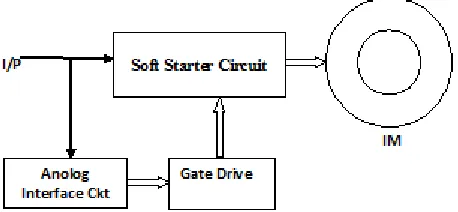
[image:2.612.54.283.312.418.2]This paper focuses on the classical topology of the soft starter based on thyristor and IGBT power switches for induction motor. Thus this surely affects the starting of induction motor on load. Additionally the output voltage quality is poor resulting in high distortion and poor power factor. For higher values of firing angle, THD is elevated. When the load is vacuous the soft starter method is dexterous. The major improvement with this scheme is the continuous ac side input current in contrast to the conventional ac regulator where the input current happens to be discontinuous. Triggering angle of the thyristor defines switching function and controller implements it. This in turn improves the transient response. This method mends the execution of the motor by dislodging the supply frequency torque pulsation. Block diagram of split phase induction motor with soft starter is shown in fig.
Fig. 1 Block Diagram of Soft-Starter Controlled induction motor drive
II. ACVOLTAGE REGULATOR
Regulators powered from AC power circuits can use silicon controlled rectifier (SCRs) as the series device. Whenever the output voltage is below the desired value, the SCR is triggered, allowing electricity to flow into the load until the AC mains voltage passes through zero (ending the half cycle). SCR regulators have the advantages of being both very efficient and very simple, but because they cannot terminate an on-going half cycle of conduction, they are not capable of very accurate voltage regulation in response to rapidly-changing loads. An alternative is the SCR shunt regulator which uses the regulator output as a trigger, both series and shunt designs are noisy, but powerful, as the device has a low on resistance.
Variable frequency IGBT convertor fed method is widely used to control the speed harmonic, and starting current , voltage, rotor speed , output torque of a squirrel cage induction motor (IM) over a wide range by varying the stator frequency.
In particular the IGBT fed induction motor are widely preferred in industries for individual medium to high power variable speed drive system, driving a group of motors connected in parallel at economic cost. The IGBT can switch on and off several thousand times per second and precisely control the power delivered to the motor.
III. DEVELOPMENT OF MATLAB/SIMULINKMODEL
Simulink is a software package that enables you to model, simulate, and analyze systems whose outputs change over time. Such systems are often referred to as dynamic systems. The Simulink software can be used to explore the behavior of a wide range of real-world dynamic systems, including electrical circuits, shock absorbers, braking systems, and many other electrical, mechanical, and thermodynamic systems. This section explains how Simulink works.
Simulating a dynamic system is a two-step process. First, a user creates a block diagram, using the Simulink model editor, that graphically depicts time-dependent mathematical relationships among the system's inputs, states, and outputs. The user then commands the Simulink software to simulate the system represented by the model from a specified start time to a specified stop time.
The sample time of a block is a parameter that indicates
when, during simulation, the block produces outputs and if appropriate, updates its internal state. The internal state includes but is not limited to continuous and discrete states that are logged.
282
The Simulink product extends these classic block diagram models by introducing the notion of two classes of blocks, nonvirtual blocks and virtual blocks. Nonvirtual blocks represent elementary systems. Virtual blocks exist for graphical and organizational convenience only: they have no effect on the system of equations described by the block diagram model. You can use virtual blocks to improve the readability of your models.
The term "time-based block diagram" is used to distinguish block diagrams that describe dynamic systems from that of other forms of block diagrams, and the term block diagram (or model) is used to refer to a time-based block diagram unless the context requires explicit distinction. A Simulink block diagram can consist of layers. Each layer is defined by a subsystem. A subsystem is part of the overall block diagram and ideally has no impact on the meaning of the block diagram. Subsystems are provided primarily to help with the organizational aspects of a block diagram. Subsystems do not define a separate block diagram.
The Simulink software differentiates between two different types of subsystems: virtual and nonvirtual. The primary difference is that nonvirtual subsystems provide the ability to control when the contents of the subsystem are evaluate.
In the modern era, almost all the processes and techniques are at first simulated before their actual real time implementation. This reduces a significant portion of effort and cost of real time implementation. The performance of the proposed System /process /technique can be evaluated accurately by using proper simulation models. The main advantage of the SIMULINK over other programming software is that, instead of compilation the simulation model is built systematically by means of function blocks. A set of machine differential equations can be modelled by interconnection of appropriate blocks, each of which performs a specific mathematical operation. Since the SIMULINK is model operation programme, the simulation model can be easily developed by addition of new sub-models to cater for various control functions. The induction motor could be incorporated in the complete electric motor drive system from Simulink Library. The complete simulation model of a single-phase voltage regulator for soft starting of induction machine using thyristors is shown in Figure. Single-phase sinusoidal voltage is generated using voltage source block from Simulink Library.
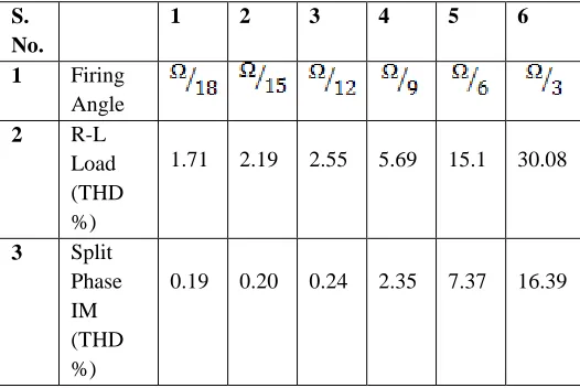
[image:3.612.331.569.111.269.2] [image:3.612.332.595.328.504.2]Fig.2 Single-Phase Soft Starter Using Thyristors With R-L Load TABLE 1
THD for various firing angle for thyristor based soft starter
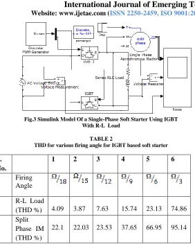
Fast switching devices are commonly used these days for all industrial applications. Thyristors have low switching frequency so the fast switching devices such as MOSFETs and IGBTs are used. Here discrete PWM generator is used for controlling purpose. Thus a simulation model is developed in this section incorporating a soft start system using IGBTs as shown in Figure below.
S. No.
1 2 3 4 5 6
1 Firing Angle
2 R-L
Load (THD %)
1.71 2.19 2.55 5.69 15.1 30.08
3 Split Phase IM (THD %)
283
Fig.3 Simulink Model Of a Single-Phase Soft Starter Using IGBT With R-L Load
TABLE 2
THD for various firing angle for IGBT based soft starter
The RMS value of the nth harmonic of input current corresponding with the following relation:
In = 1/ (an2 + bn2)1/2………. (1)
In = ……… (2)
Where
an= [ ]
and
bn = [ ]
The total rms value is given by following eq.:
I(rms) = (I1(rms)+ I2(rms)+I3(rms)+I4(rms)……….+In(rms))1/2…….(3)
Input current of the system is given by following eq.
Ia = (2 ) Id 1) + 1) +
1) + 1) +…..] ….. (4)
Where = Phase angle between source voltage and current
The source voltage is given by the following eq.
Va=√2 Vs sin ωt ………. (5)
The output voltage is given by
Vo = { Vs2 sin (ωt) d (ωt)} 1/2 ……… (6)
Vo = Vs {1 - + }1/2 ……… (7)
Where, is a conduction angle
Vo = Output RMS voltage Io= Output RMS Current Is = Input RMS current
Total harmonic distortion is defined as the ratio of the rms value of all harmonic components to the rms value of the fundamental frequency:
THD = .………… (8)
Total Harmonic Distortion in terms of power :
THD = ……….. (9)
Total Harmonic Distortion in terms of voltage:
…………
Input and output power of non-sinusoidal waveforms can be obtained by
Poutput = Vrms(o/p) Irms(o/p) …………..…….. (11)
…... (10)
Irms(o/p) = {1 - + } 1/
2………. …….(13)
IV. RESULT
Fig.4 Thyrister and IGBT based model i/p voltage at R-L load S.
No.
1 2 3 4 5 6
1 Firing Angle
2 R-L Load
(THD %) 4.09 3.87 7.63 15.74 23.13 74.86 3 Split
Phase IM (THD %)
284
Fig.5 Thyristor based model o/p voltage at R-L load
Fig.6 Frequency vs. Time for Thyristor based model
Fig.7 Total harmonic distortion at50 Hz frequency
Fig.8 O/P Voltage waveform Of IGBT based model
Fig.9 Frequency vs. Time for IGBT based model
Fig.10 Total harmonic distortion at 50 Hz frequency
V. CONCLUSION
The paper discusses the performance of induction motor drive supplied from a variable voltage soft starter. It is concluded that when the firing angle goes high, speed changes and THD also increases with increasing firing angle, motor fails in critical cases. As IGBTs requires filters to be used as power switch, large amount of distortion cab be observed in the input voltage which results in drive system instability, we set firing angle is set at its minimum value for reducing fluctuation and THD.
VI. NOMENCLATURE
285
REFERENCES
[1] D.Venkatasubramanian, S. P. Natarajan, B. Baskaran S. Suganya, Dual Converter Controlled Single Phase Matrix Converter Fed Dc Drive, ARPN Journal of Engineering and Applied Sciences, 7, June 2012.
[2] Mehran Mirjafari, Robert S. Balog, Multi-objective design
optimization of renewable energy system inverters using a Descriptive language for the components, Applied Power Electronics Conference and Exposition (APEC), 2011 Twenty-Sixth Annual IEEE, pp.1838 – 1845.
[3] F. Blaabjerg, F. Iov, T. Kerekes, R. Teodorescu, ,Trends in power electronics and control of renewable energy systems, Power Electronics and Motion Control Conference (EPE/PEMC), 2010, pp. K-1 - K-19.
[4] Maria IMECS, Csaba SZABO, Ioan Iov INCZE, Modeling and
simulation of controlled bi-directional power electronic converters in a DC energy distribution line with AC grid- and motor-side active filtering, Power Electronics and Applications, 2007 ,pp.1–10.
[5] M.A Mahar, M.A Uqaili, A.S Larik, Harmonic analysis of AC-DCtopologies and their impacts on power system, Mehran University of Engineering and technology, 30, Jan, 2011.
[6] A.S larik, M.A.Mahar, A.R Sheikh, Perform analysis of phase Controlled unidirectional and bidirectional AC voltage controller, Mehran University of Engineering and technology, 30, Jan, 2011. [7] M.A. Mahar, A.S Larik, Syed Asif Ali Shah, Impacts on power
factor of AC voltage controllers under nonsinusoidal condition, Mehran University of Engineering and technology, 3, April, 2012. [8] Santosh S. Raghuwanshi Ankita Singh Yamini mokhariwale, A
Comparison & Performance of Simulation Tools