An Integrated Emission Control For a Connected
Transportation System
JENITH KUMERSAN.P
Assistant Professor UG Scholar
Department of Electronics & Communication Engineering Department of Electronics & Communication Engineering Christian College of Engineering & Technology Christian College of Engineering & Technology
Oddanchatram, Oddanchatram,
MAHA PRABHU P RAJ KANNAN.V
UG Scholar UG Scholar
Department of Electronics & Communication Engineering Department of Electronics & Communication Engineering Christian College of Engineering & Technology Christian College of Engineering & Technology
Oddanchatram, Oddanchatram,
RAM KUMAR
UG Scholar
Department of Electronics & Communication Engineering Christian College of Engineering & Technology, Oddanchatram
Abstract
This paper designs an embedded system for a vehicle cabin, which senses the gases like carbon-monoxide and oxygen and displayed at each and every second. A warning message is sent to the authorized user via GSM. The advantage of this system is proper detection and faster response time leading to faster diffusion of the situation, compared with the manual methods. To give intimation to RTO office, RTO can control the speed of vehicle through remote PC
Keywords: Gas detecting sensors,GSM modem, Picmicrocontroller,Ultrasonic distance sensor
________________________________________________________________________________________________________
I. INTRODUCTION
It is common that on a typical day in modern society, a person has to face a considerable number of problems with current transportation systems, such as traffic congestion and parking difficulties, longer commuting times, higher levels of CO2 emissions, and an increased number of accidents, among others. Consequently, modern society could face serious problems with traffic congestions. Finally, even though the economic costs of transportation are significant, the human cost resulting from vehicular accidents is high. According to the Commission for Global Road Safety, road crashes kill at least 1.3 million people each year and injure 50 million, with 90 percent of these road casualties occurring in low and middle-income countries. These motor vehicles contribute to over 30% of the hazardous gases that are released into the atmosphere. The embedded system is used inside a vehicle cabin such that the presence or leakage of toxic gases can be detected by the gas sensors and proper precautions can be taken to avoid the driver from getting fatigue or drowsiness.
II. RELATED WORK
Maintaining the Integrity of theSpecificationsExperimen information is provided here on the emission measurement equipment.
Emission Measurement Equipment
The Axion system, which is a portable emission measurement system, was used to measure the emissions and fuel consumption of the vehicles in real operating conditions. In each mobile test, the Axion equipment was first setup onboard the vehicle, a short version
vehicles found that the bias between the Axion NO sensor and laboratory chemiluminescence NOx measurements ranged between −l21.3% and 8.48% . Nitrogen oxide (NOx) emissions from conventiona l heavy-duty diesel engines is comprised of 90–95% which is considered when comparing NO measurements from the Axion system to NOx emissions data reported from other studies. HC, CO, and CO2 are measured using a non-dispersive infrared (NDIR) sensor. CO and CO2 measurements in the laboratory for emissions certification are also made using NDIR. In comparisons with laboratory grade NDIR sensors for light duty gasoline tests, the Axion sensor performed quite well(bias ranging from −12.9% to 5.4%), whereas CO2 exhibited more bias (8.09%–44.7%). HC measurements for emission certification are made using flame ionization detectors (FIDs). The Axion HC measurements showed the most bias of the gaseous measurements in comparison to the reference HC laboratory methods (11.2%–63.9%), as well as the smallest linear correlation between the measurements across different tests. Bias between FID and NDIR measurements of HC has been observed by previous researchers where NDIR measurements has been observed to require correction factors ranging from 1.5 ∼ 4.4 to correspond to FID measurements of light-duty vehicle exhaust. The response factor for the instruments varies on individual HC compounds; thus, the differences depend on the HC composition of the exhaust stream being measured and the HC used to calibrate the NDIR and FID instruments The NDIR within the Axion System used in this paper were not calibrated to FID measurements from the diesel engines measured in this paper. The Axion System measures the engine speed, intake air temperature, and boost pressure (for turbocharged engines) from which the Axion estimates the exhaust flow rate. It estimates the fuel rate using a carbon balance based on the measurements of CO2, CO, HC, the specified carbon content of the diesel fuel, and the calculated exhaust flow rate.The CO2 measurements contribute 97.5% of the carbon balance across the different vehicle tests, with more than 95% across all vehicles. Fuel consumption data estimated from the Axion system was compare with volumetric measurements during the stationary tests by measuring the fuel needed to return the fuel tank to full
Fig. 1: Fuel consumption rates by hours of operation, kilometer mowed, and hectare mowed.
real-world conditions by 13 different vehicle operators .Third, the vehicles were typically only tested with one mower configuration used by NYSDOT. As such, the individual vehicle type, mower type, the operating conditions (length of grass, slope of highways, area of mowing), and the style of the vehicle operator are difficult to estimate because they are not controlled individually with an experimental design. The sensor is available at the outside of the vehicle. Gas sensor fixed at traffic region and emission checking center. In traffic region, few vehicles may misses the gas sensor cover area. Emission check center-false report. Only fine will be collected by the RTO, in case of no emission check. That particular vehicle will keep on emitting hazardous gas, till that vehicle is caught by RTO.
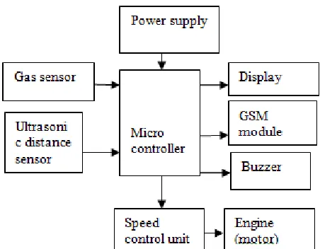
Hardware description
Fig. 2: Block Diagram for vehicle unit
Proposed system
To check the pollutant emission level of exhaust air in the vehicle is in the specified limit. Intimation to RTO office, when the exhaust smoke level crosses this specified level. RTO can control the speed of the vehicle from remote PC- when no action taken by vehicle owner during more emission. A low cost rear end collision warning and control system is also implemented for Indian market. To fix the gas sensor inside the vehicle unit. Gas sensor level crosses the specified value, buzzer will alarm inside the vehicle and then the SMS will be sending to RTO and owner. The RTO server will replay back with the grace period to vehicle/vehicle owner to repair the emission unit.
Peripheral interface controllers (PIC)
Peripheral Interface Controllers (PIC) is one of the advanced microcontrollers developed by microchip technologies. These microcontrollers are widely used in modern electronics applications. A PIC controller integrates all type of advanced interfacing ports and memory modules. These controllers are more advanced than normal microcontroller like INTEL 8051. The first PIC chip was announced in 1975 (PIC1650). As like normal microcontroller, the PIC chip also combines a Microprocessor unit called CPU and is integrated with various types of memory modules (RAM, ROM, EEPROM)
Peripheral Features:
- Timer0: 8-bit timer/counter with 8-bit prescaler
- Timer1: 16-bit timer/counter with prescaler, can be incremented during Sleep via external crystal/clock - Timer2: 8-bit timer/counter with 8-bit period register, prescaler and postscaler
- Two Capture, Compare, PWM modules - Capture is 16-bit, max. resolution is 12.5 ns - Compare is 16-bit, max. resolution is 200 ns - PWM max. resolution is 10-bit
- Synchronous Serial Port (SSP) with SPI (Master mode) and I2C™(Master/Slave) - Universal Synchronous Asynchronous Receiver
Transmitter (USART/SCI) with 9-bit address detector
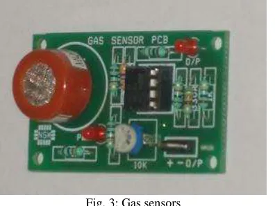
Gas sensors
warnings via a series of audible signals such as alarms and visible signals such as flashlights, as they meet dangerous levels. This is a simple-to-use Carbon Monoxide (CO) sensor, suitable for sensing CO concentrations in the air. The MQ-7 can detect CO-gas concentrations anywhere from 20 to 2000ppm.
This sensor has a high sensitivity and fast response time. The sensor’s output is an analog resistance. The drive circuit is very simple; all you need to do is power the heater coil with 5V, add a load resistance, and connect the output to an ADC.
Features
- High sensitivity to carbon monoxide - Stable and long life
Application
They are used in gas detecting equipment for carbon monoxide(CO) in family and industry or car.
Fig. 3: Gas sensors
GSM Modem
GSM (Global System for Mobile Communications: originally from Group Special Mobile) is the most popular standard for mobile telephony systems in the world. The GSM association has its promoting industry trade organization of mobile phone carriers and manufactures, estimate that 80% of the global mobile market uses this standard. A GSM modem is wireless modem that works with a GSM wireless network. GSM modem requires a SIM card from a wireless carrier in order to operate. A GSM available service like SMS (Short Message Service) represents alternative modalities to make remote measurements and control. SMS service is suited for remote control applications that requires.
Fig. 4: Block Diagram of GSM
Ultrasonic Sensor
The transmitter emits 8 bursts of an directional 40KHz ultrasonic wave when triggered and starts a timer. Ultrasonic pulses travel outward until they encounter an object, The object causes the wave to be reflected back towards the unit. The ultrasonic receiver would detect the reflected wave and stop the stop timer. The velocity of the ultrasonic burst is 340m/sec. in air. Based on the number of counts by the timer, the distance can be calculated between the object and transmitter The TRD Measurement formula is expressed as:
D = C X T which is known as the time/rate/distance measurement formula where D is the measured distance, and R is the propagation velocity (Rate) in air (speed of sound) and T represents time. In this application T is divided by 2 as T is double the time value from transmitter to object back to receiver.
Fig. 6: Ultrasonic sensor
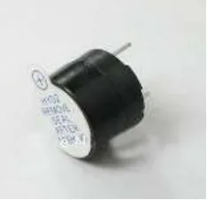
Buzzer
The transistor used in this project to drive the buzzer is BC547. The features of this transistor are discussed in the next topics.Digital systems and microcontroller pins lack sufficient current to drive the circuits like buzzer circuits and relay circuits(3). While these circuits need around 10milli amps to be energized, the microcontroller pin can provide a maximum of 1-2milli amps current. For this reason, a driver such as a power transistor is placed in between the microcontroller and the buzzer. This is a small 12mm round speaker that operates around the audible 2kHz range. You can use these speakers to create simple music or user interfaces. Each speaker is PTH solderable and requires an operating voltage of 3.5-5V with a mean current of 35mA max. These speakers also have a typical sound output of 95 dBA and a coil resistance of 42 ±6.3 ohm
Fig.7: Buzzer
Features
- Low current (max. 100 mA) - Low voltage (max. 65 V). - Annunciator panels - Electronic metronomes - Game show lock-out device
- Microwave ovens and other household appliances - Sporting events such as basketball games - Electrical alarms
III. SOFTWARE DESCRIPTION
MPLAB IDE Basics
MPLAB IDE is a software program that runs on a PC to develop applications for Microchip microcontrollers. It is called an Integrated Development Environment, or IDE, because it provides a single integrated “environment” to develop code for embedded microcontrollers. Once the code builds with no errors, it needs to be tested. MPLAB IDE has components called “debuggers” and free software simulators for all PIC micro and ds PIC devices to help test the code. Even if the hardware is not yet finished, you can begin testing the code with the simulator, a software program that simulates the execution of the microcontroller. The simulator can accept a simulated input (stimulus), in order to model how the firmware responds to external signals. The simulator can measure code execution time, single-step through code to watch variables and peripherals, and trace the code to generate a detailed record of how the program ran. Once the hardware is in a prototype stage, a hardware debugger, such as MPLAB ICE or MPLAB ICD 2 can be used. These debuggers run the code in real time on your actual application. The MPLAB ICE physically replaces the microcontroller in the target using a high-speed probe to give you full control over the hardware in your design. The MPLAB ICD 2 uses special circuitry built into many Microchip MCUs with Flash program memory and can “see into” the target micro controller’s program and data memory. The MPLAB ICD 2 can stop and start program execution, allowing you to test the code with the microcontroller in place on the application. After the application is running correctly, you can program a microcontroller with one of Microchip device programmers, such as PICSTART Plus or MPLAB PM3. These programmers verify that the finished code will run as designed. MPLAB IDE supports most PIC micro MCUs and every ds PIC Digital Signal Controller.
The process for writing an application is often described as a development cycle - as it is rare that all the steps from design to implementation can be done flawlessly the first time. More often code is written, tested and then modified in order to produce an application that performs correctly. The Integrated Development Environment allows the embedded systems design engineer to progress through this cycle without the distraction of switching among an array of tools. By using MPLAB IDE, all the functions are, allowing the engineer to concentrate on completing the application
without the interruption of separate tools and different modes of operation.
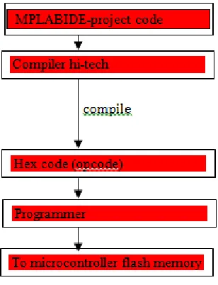
Software
Fig. 9: Software Block for MPLAB Basics
integrated, allowing the engineer to concentrate on completing the application without the interruption of separate tools and different modes of operation.
IV. CONCLUSION
This paper results in the pollution control, also interfaces the modules like GSM , with the controller PIC16F877A offering the high end outputs .The values as output is successfully carried out in this paper. Here the two sections are used and with the help of GSM the messages are transferred and received as well. The future scope, we can make the ignition system Off due to high rates of pollution in the vehicles on busy roads indication the flash lights on and a audio buzzer too.
V. FUTURE SCOPE
REFERENCE
[1] Energy Consumption and Emission Rates of Highway Mowing Activities Darrell B. Sonntag, H. Oliver Gao, Patrick Morse, and Mary O’Reilly
[2] Mitigation Strategies for Design Exceptions, Chapter 3: The 13 Controlling Criteria. Stopping Sight Distance, Federal Highway Administration (FHWA),
U.S. Dept. Transp., Washington, DC, USA, Jul. 2007. [Online]. Available:
http://safety.fhwa.dot.gov/geometric/pubs/mitigationstrategies/chapter3/3_stopdistance.htm
[3] “Modeling air quality and energy of NYSDOT highway ROW practices,” Region 2 Univ. Transp. Res. Center, New York, NY, USA, NYSDOT RFP:
C-07-13, Nov. 9, 2007 [Online]. Available: http://www.utrc2.org/research/rfps/c0713.pdf
[4] D. A. Nelson, G. R. McVoy, and L. Greninger, “Promoting environmental Steward ship in transportation maintenance and operations at the New York
State Department of Transportation Research Record 1792,” New York State Dept. Transp. Transp. Res., Albany, NY, USA, Paper 02-2811, 2002.
[5] Environmental Handbook for Transportation Operations, NYSDOT,Albany, NY, USA, 2009, Accessed Jan. 2010. [Online].
Available:https://www.nysdot.gov/portal/page/portal/divisions/engineering/environmentalanalysis/repository/oprhbook.pdf
[6] “Clean air nonroad diesel rule–Facts & figures,” U.S. EPA, Washington,DC, USA, EPA 420-F-04-037, 2004, Accessed Jul. 26, 2010. [Online] .Available:
http://www.epa.gov/nonroad-diesel/2004fr/420f04037.htm
[7] Embedded Technology for vehicle cabin safety Monitoring and Alerting System.V.Ramya1, B. Palaniappan2.