International Journal of Emerging Technology and Advanced Engineering
Website: www.ijetae.com (ISSN 2250-2459, ISO 9001:2008 Certified Journal, Volume 9, Issue 2, February 2019)
95
Standalone Wind Energy Conversion System Control Using
New Maximum Power Point Tracking Technique
I. M. Abdelqawee
1, Ayman Y. Yousef
2, Khaled M. Hasaneen
3, Maged N. F. Nashed
4, H. G. Hamed
5 1,2,3,5Electrical Engineering Dept., Faculty of Engineering at Shoubra, Benha University, Egypt4Dept. of Power Electronics and Energy Conversion, Electronics Research Institute, Egypt
Abstract— This paper presents a new maximum power
point tracking (MPPT) technique control strategy for a variable speed stand-alone wind turbine with a permanent magnet synchronous generator (PMSG). The PMSG is controlled to achieve maximum power extraction from the available wind power. This control technique contains the merits of both perturb and observe (P&O) technique and the tip speed ratio (TSR) technique. The P&O technique is modified to be a variable duty cycle steps and the TSR is used to improve the steady state performance. The PMSG is connected to a DC/DC boost converter through a three-phase uncontrolled rectifier. The system is modeled and simulated by using Matlab/Simulink package under different wind speed.
Keywords— Maximum power point tracking (MPPT),
Permanent magnet synchronous generator (PMSG), Perturb and observe (P&O), Tip-speed ratio (TSR).
I. INTRODUCTION
Wind energy is the fastest growing renewable energy due to its free availability and environmental benefits [1]. It is one of the most efficient renewable energy sources for the generation of electrical energy from the kinetic energy [2]. The main components of the wind energy conversion system (WECS) are two main parts: mechanical part (aerodynamic rotor and gear box) and electrical part (electrical generator, power electronics converters, and electrical loads) [3].
The mechanical power extracted from the wind turbine (WT) is converted to an electrical power through an appropriate generator. There are many types of generators are used. The major difference among them is using a fixed speed or as variable speed WT [4]. The PMSG is used in this paper as it has many advantages compared to other generators such as: high energy produced, high power density, High active and reactive power controllability, absence of brush or slip ring, and low mechanical stress [5].
As known, the wind turbines are designed to operate at specified wind speed. This speed is limited between the in speed, at which the turbine starts working, and cut-out speed, at which the turbine stops working [6].
Between these limits the turbine must be controlled to capture the maximum power. The maximum extracted energy is achievable only with variable speed wind turbines as they can change the generator rotational speed to follow the instantaneous changes in the wind speed [7]. Hence, they are able to maintain a constant rotational speed to wind speed ratio. In other words, in order to operate at this point, the generator speed should be changed to operate at the optimal tip speed ratio.
The generator rotational speed through power electronics converters will be controlled to be able to capture as much electrical power as possible from the available wind power in the shortest time. This objective can be achieved through different power electronics converters topologies and different MPPT algorithms [8-10]. These algorithms can be classified according to method and type of generating the reference control signals, the number of sensors which are required, the tracking time, the complexity of the hardware implementation, memory requirement, and the algorithms performance under varying wind speeds [11].
The MPPT algorithms are classified into three types based on the methodology employed in generating the reference signal (voltage/torque/speed). These types are: the methods which uses the reference speed such as TSR control and Power-Signal feedback (PSF), methods that are used the reference voltage such as Hill climb search (HCS), methods that are used the generator torque as a reference signal such as an optimal torque control (OTC) [2, 7]. Another classification of MPPT techniques based on sensor required for measuring the wind velocity can be divided into two types: Sensor based MPPT methods such as TSR control and Sensorless MPPT methods such as P&O and PSF control [12]. The proposed algorithm in this paper is combination between TSR method and P&O method to obtain the advantages from both algorithms
II. MATHEMATICAL MODELLING OF THE SYSTEM PARTS
A. Modeling of the aerodynamic wind turbine
International Journal of Emerging Technology and Advanced Engineering
Website: www.ijetae.com (ISSN 2250-2459, ISO 9001:2008 Certified Journal, Volume 9, Issue 2, February 2019)
96
31
( , ) 2
m w p
P Av C (1)
Where, ρ is the air density (Kg/m3), A is the blades
swept area, vw is the wind speed (m/sec), and CP (λ,β) is the
power coefficient, which is defined as the ratio of turbine power to wind power and it is a function of the pitch angle (β) and the tip speed ratio (λ). The tip speed ratio is the ratio between the rotor speed and the wind speed as given by:
Rb vw
(2)
Where: ω is the blades angular velocity (rad/sec) and Rb
is the rotor blade radius (m). The equation that describes the power coefficient has been reported by different fitted equations [4, 13]. In this study, the power coefficient can be calculated as [14]:
21 116
( , ) 0.5167*( 0.4 5) 0.0068
Cp e
(3)
Where,
1 1 0.035
3
0.08 1
(4)
The Maximum power can be extracted from the WT when it operates at the optimal value of Cp , Cp-opt.
Therefore, it is necessary to adjust the rotor speed at optimum value of tip speed ratio (λopt) with variation in
wind speed.
B. Permanent Magnet Synchronous Generator Model
In The PMSG, the excitation field is obtained using permanent magnets in the rotor. The equivalent circuit of the PMSG on the d-q synchronous rotating reference frame is shown in Fig.1 [4].
The modeling of the PMSG is written in d-q synchronous rotating reference frame as formulated in the following equation [4, 15-17]:
1
1 L
did Ra i q
p i u
d e q d
dt Ld Ld Ld
diq R p f e
a iq p e di ud
dt Lq Lq Lq
(5)
where id , iq are the d- and q-axis components of current
respectively; Ra is the armature resistance; Ld , Lq are the
generator inductance on the d-q axis; ud , uq are the d- and
q-axis voltage components, respectively, p and ωe are the
number of pole pairs and the electrical rotating angular speed, ωe= pω, of a PMSG respectively; ψf is the
permanent magnet flux. The electromagnetic torque (Te)
and the equation of motion for a PMSG can be expressed as [18]:
1.5
1 Te piq f
T B
d w m
Te
dt J J J
(6)
Where J is the rotational inertia of the generator, where there isn’t any gearbox, and Bm is the damping coefficient
[image:2.612.50.247.358.449.2].
Fig. 1 Equivalent circuit of a PMSG in the d-q synchronous frame [4], (a) q-axis, (b) d-axis
III. PROPOSED MPPTCONTROL METHOD
The block diagram of the overall wind energy conversion system is shown in Fig. 2. The system consists of 20 kW WT with PMSG. The output of the generator is connected to three-phase uncontrolled bridge rectifier and the output of the bridge rectifier is connected to DC-DC boost converter for tracking the MPP at any wind speed. The proposed MPPT is a modified P&O with variable duty cycle steps based on TSR. The measured inputs are the wind speed as in the TSR method, turbine speed, and the turbine power as in the P&O method.
International Journal of Emerging Technology and Advanced Engineering
Website: www.ijetae.com (ISSN 2250-2459, ISO 9001:2008 Certified Journal, Volume 9, Issue 2, February 2019)
97
The generated variable steps depend on the position of the operating point from the MPP. The variable steps are changed from 0.75*Dmin to 0 with seven different steps.
Where, Dmin is equal 0.001. The percentage of absolute
Δω/ωopt is determined which step will be produced. The
[image:3.612.326.569.132.426.2]output of this subsystem is ΔD which will be used to increase or decrease the pervious duty cycle depends on the sign of P&O algorithm.
Fig. 2 Block diagram of wind energy conversion system
IV. SIMULATION MODEL OF THE PROPOSED SYSTEM
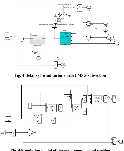
Simulink block diagram of the wind turbine with MPPT feed DC load is shown in Fig. 3. The details of the wind turbine with PMSG block is shown in Fig. 4 which consists of the simulation model of the aerodynamic turbine and the simulation model of the PMSG. The details of the simulation model of the aerodynamic turbine are shown in Fig. 5. The model is based on the equations from (1) to (4). The simulation model of the proposed MPPT control is shown in Fig. 6. The variable duty cycle steps are seven steps and the details of these steps are shown in Fig.7. All paragraphs must be indented. All paragraphs must be justified, i.e. both left-justified and right-justified.
DC-DC boost converter
3-phase rectifier Wind turbine with PMSG
[image:3.612.55.282.234.282.2]P&O MPPT controller DC link (filter)
Fig. 3 Simulink block diagram of the WECS
Fig. 4 Details of wind turbine with PMSG subsection
β
vw
ω Rb
eqn. (4)
eqn. (3)
eqn. (1)
eqn. (2)
Pm
Tw
Fig. 5 Simulation model of the aerodynamic wind turbine
vw ωm Pm
D
D
Variable duty cycle Memory
Fig.6 Simulation model of the proposed MPPT control
D
%|ω/ ω opt|
Dmin
[image:3.612.60.293.465.588.2]International Journal of Emerging Technology and Advanced Engineering
Website: www.ijetae.com (ISSN 2250-2459, ISO 9001:2008 Certified Journal, Volume 9, Issue 2, February 2019)
98
V. SIMULATION RESULTS AND DISCUSSION
The WECS which is used for the simulation has two parameters. The first is the wind turbine parameters which contain: Pm = 20 kW at Vw = 12 m/s, Rb = 4 m, and
Copt=0.48. The second is the three-phase PMSG generator
parameters which have: 20 kW, Ra = 0.176 Ω; Ls = 4.48
mH, ψf = 0.742 V.sec; pair poles, p = 18; J = 1.8 kg.m2.
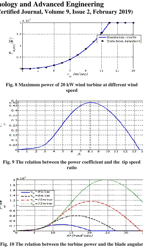
In order to validate the mathematical model of the aerodynamic WT, the simulation results will be obtained and compared with a 20 kW WT data from the catalogue of European Urban WT manufacturers [19] as shown in Fig. 8. It can be seen from the figure that the simulation results obtained are very close to those obtained from the manufacture datasheet. The relation between Cp and λ
when the pitch angle equals zero degree is shown in Fig. 9. It can be verified that the optimum value of Cp is about
0.48 at λ equal 8.1 whatever the value of the wind speed [13]. The relation between the blade rotational speed and the mechanical turbine power at different values of the wind speed and at β=0o is shown in Fig. 10. It can be concluded from the figure that the maximum mechanical power of the WT is occurred at a particular rotational speed. Hence, the tip speed ratio which is function in the rotational speed should be kept at the optimal value (λopt) to
maximize the wind energy [20].
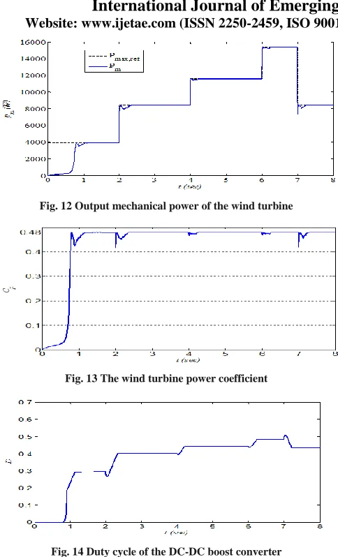
[image:4.612.325.562.105.517.2]The performance of the WECS is studied under different rapid change in the wind speed. The wind speed is changed as stairs shape 7, 9, 10, 11, and 9 m/sec as shown in Fig. 11. The output power of the turbine is shown in Fig. 12 which proves that the turbine output power is operated at the MPP. The maximum tracking time occurs at starting operation and equal to 1.1 sec. The tracking time is reduced to 0.3 sec in the next wind speeds. The fluctuation of the turbine power around the MPP is nearly zero. The power coefficient of the wind turbine is shown in Fig. 13. The figure shows that the wind turbine is operated at the optimal power coefficient (0.48) whatever the wind speed values. The DC-DC converter duty cycle is shown in Fig. 14. At each wind speed, there is an optimal value of duty cycle at which the turbine will be operated at MPP. The figure also shows that as the wind speed is increased, the duty cycle is increased.
Fig. 8 Maximum power of 20 kW wind turbine at different wind speed
Fig. 9The relation between the power coefficient and the tip speed ratio
[image:4.612.326.568.536.650.2]Fig. 10 The relation between the turbine power and the blade angular speed at different values of wind speed, β=0o
International Journal of Emerging Technology and Advanced Engineering
Website: www.ijetae.com (ISSN 2250-2459, ISO 9001:2008 Certified Journal, Volume 9, Issue 2, February 2019)
[image:5.612.49.291.108.507.2]99
Fig. 12 Output mechanical power of the wind turbineFig. 13 The wind turbine power coefficient
Fig. 14 Duty cycle of the DC-DC boost converter
VI. CONCLUSION
In this paper, it has been observed that the wind energy conversion system controlled with a proposed MPPT has good steady state performance and high tracking factor. The steady state fluctuation power is very small and reaches to zero as the controller maintain the duty cycle at its optimal value when the wind turbine produces the maximum available power at certain wind speed. The power coefficient of the wind turbine is maintained at the optimal value whatever the values of the wind speed.
REFERENCES
[1] P. Costa, A. Martins, and A. Carvalho, ―Wind Energy Extraction and Conversion: Optimization through Variable Speed Generators and Non Linear Fuzzy Control‖, 16th International Middle- East Power Systems Conference -MEPCON'2014, Ain Shams University, Cairo, Egypt, Dec. 23 - 25, 2014.
[2] Devashish, A. Thakur, S. Panigrahi, and R. R. Behera, ―A Review on Wind Energy Conversion System and Enabling Technology‖, International Conference on Electrical Power and Energy Systems (ICEPES), Maulana Azad National Institute of Technology, Bhopal, India. Dec. 14-16, 2016.
[3] F. Blaabjerg, Z. Chen, R. Teodorescu; and F. Iov, ―Power Electronics in Wind Turbine Systems‖, 5th International Power Electronics and Motion Control Conference, Shanghai, China, Aug. 14-16, 2006.
[4] Ming Yin, Gengyin Li, Ming Zhou, and Chengyong Zhao, ―Modeling of the Wind Turbine with a Permanent Magnet Synchronous Generator for Integration‖, IEEE Power Engineering Society General Meeting, Tampa, USA, pp. 1-6, 24-28 June 2007. [5] Hyong Sik Kim, Dylan Dah, and Chuan Lu, ―Wind Energy
Conversion System from Electrical Perspective —A Survey‖, Smart Grid and Renewable Energy, Vol. 1, , pp. 119-131, 2010.
[6] Abdullah M. A. , Yatim A.H.M, Tan C.W., and Saidur R., ―A review of maximum power point tracking algorithms for wind energy systems‖, Renewable and Sustainable Energy Reviews, Elsevier, Vol. 16, pp. 3220– 3227, 2012.
[7] Ameni Kadri, Hajer Marzougui, and Faouzi Bacha, ―MPPT Control Methods in Wind Energy Conversion System Using DFIG‖, 4th International Conference on Control Engineering & Information Technology (CElT -2016) Tunisia, Hammamet Dec. 16-18, 2016. [8] P.Venkatesan, C.Yasodha, and K.Madhumathi, ―Modified Hybrid
MPPT for Hybrid Renewable Energy Conversion System‖,
International Electrical Engineering Journal (IEEJ), Vol. 8 (2018) No.2, pp. 2498-2502.
[9] M. Azouz, A. Shaltout, M. A. L. Elshafei, N. Abdel-Rahim, H. Hagras, M. Zaher, and M. Ibrahim, ―Fuzzy Logic Control of Wind Energy Systems‖, 14th International Middle East Power Systems Conference (MEPCON’10), Cairo University, Egypt, pp. 935-940, Dec. 19-21, 2010.
[10]Dwiana Hendrawati, Adi Soeprijanto, and Mochamad Ashari, ―High Performance Maximum Power Point Tracking on Wind Energy Conversion System‖, International Journal of Power Electronics and Drive System (IJPEDS), Vol. 8, No. 3, pp. 1359-1367, Sep. 2017. [11]Shravana Musunuri and H. L. Ginn, ―Comprehensive Review of
Wind Energy Maximum Power Extraction Algorithms‖, Power and Energy Society General Meeting, Detroit, MI, USA, pp. 1-8, 24-29 July 2011.
[12]Shilpa Mishra, Sandeep Shukla, Nitin Verma, and Ritu, ―Comprehensive Review on Maximum Power Point Tracking Techniques: Wind Energy‖, International Conference on Communication, Control and Intelligent Systems (CCIS), Mathura, India, pp. 464-469, 7-8 Nov. 2015.
[13]M. Azouz, A. Shaltout, M. A. L. Elshafei, N. Abdel-Rahim, H. Hagras, M. Zaher, and M. Ibrahim, ―Fuzzy Logic Control of Wind Energy Systems‖, 14th International Middle East Power Systems Conference (MEPCON’10), Cairo University, Egypt, pp. 935-940, Dec. 19-21, 2010.
International Journal of Emerging Technology and Advanced Engineering
Website: www.ijetae.com (ISSN 2250-2459, ISO 9001:2008 Certified Journal, Volume 9, Issue 2, February 2019)
100
[15]Eklas Hossain, Jakir Hossain, Nazmus Sakib, Ramazan Bayindir,―Modelling and Simulation of Permanent Magnet Synchronous Generator Wind Turbine: A Step to Microgrid Technology‖, International Journal of Renewable Energy Research, Vol.7, No.1, pp. 443-450, 2017.
[16]Yasemin Oner, Nur Bekiroglu, Selin Ozcira, ―Dynamic Analysis of Permanent Magnet Synchronous Generator with Power Electronics‖, Advances in Electrical and Computer Engineering, Vol. 10, Issue 3, pp. 11-15, Nov. 2010.
[17]Iulian Munteanu, Antoneta Iuliana, Nicolaos Antonio, Cutululis Emil Ceang, ―Optimal Control of Wind Energy Systems‖, Springer, Text book, pages. 73-74.
[18]A. Rolan, A. Luna, G. Vazquez, D.Aguilar, and G. Azevedo, ―Modeling of a Variable Speed Wind Turbine with a Permanent Magnet Synchronous Generator‖, IEEE International Symposium on Industrial Electronics (ISlE 2009), Seoul Olympic Parktel, Seoul, Korea, pp.734-739, July 5-8, 2009.
[19]Catalogue of European Urban Wind Turbine Manufacturers, Page 27.
![Fig. 1 Equivalent circuit of a PMSG in the d-q synchronous frame [4], (a) q-axis, (b) d-axis](https://thumb-us.123doks.com/thumbv2/123dok_us/8678303.874053/2.612.50.247.358.449/fig-equivalent-circuit-pmsg-synchronous-frame-axis-axis.webp)