International Journal of Emerging Technology and Advanced Engineering
Website: www.ijetae.com (ISSN 2250-2459,ISO 9001:2008 Certified Journal, Volume 5, Issue 7, July 2015)
345
Design, Simulation & Implementation of A Microcontroller
Based Seed Dryer Machine for Farm Produce Interfaced with
Computer System
Ezeofor J.C
1, Okeke. R.O
2, Ogbuokebe S.K
31,2Department of Electronic & Computer Engineering, University of Port Harcourt, Rivers State, Nigeria
3National Space Research and Development agency, Abuja
Abstract— this paper presents the design and implementation of a microcontroller based Seed Dryer Machine for farm produce interfaced with PC. Drying of farm produce and seeds in large quantity such as; melon, beans, corn, cocoa seeds, pumpkin seeds, rice, pepper seeds, tomato seeds etc., has been very challenging due to lack of drying facilities, drying space and poor weather. This gives low lifespan to the seeds and reduced quantity of stored seeds, which in turn could discourage farmers from further cultivations. In view of this problem, a microcontroller based Seed Dryer Machine is designed to aid and encourage farmers to dry in large scale different farm produce within a set time. The system is divided into nine units namely power supply, Liquid crystal display (LCD), temperature & Humidity sensors, system controller, ADC, PC, Relay driver, Heater & Fan and Alarm. The system is designed to dry any farm produce, activate an alarm when done and display the temperature and humidity values on LCD. The program codes for the controller is written in embedded C language and Graphical User interface codes written in Visual Basic.net. Some sample seeds were tested which dried as expected.
Keywords— Arduino Microcontroller, ADC, PC, LCD, Heater & Fan, Temperature & Humidity sensors, Alarm.
I. INTRODUCTION
Seed dryer machine is the Temperature and Humidity Control System that is used to measure and control the variation of temperature and the relative humidity within the seed drying chamber [1]. Drying of seeds and other farm produce after harvest have always been challenging to our indigenous farmers whereby about 30% to 40% of their farm produce when preserved during rainy seasons results in; decaying, pest destruction, and loss of fertility due to moulds growing on the seeds, or heat generated within the seeds from the presence of moisture content in the seeds [2]. The indigenous farmers end up lamenting over the loss incurred due to poor preservation of farm produce for the next planting season. Because of these, they spent more money and time during the next planting season to ensure that they gather enough seeds for their farms.
As a result of these, majority of the farmers end up bankrupt while some incur huge debt from banks, relatives or committee of friends in the process [3]. With the proposed drying system, farmers would be able to dry their farm produce using appropriate temperature and humidity control system.
II. LITERATURE REVIEW
Seed drying is as old as the existence of man, and the primitive method of drying seeds have their similarities where harvested seeds are either exposed to the sun, a room heated up with firewood, coal (with constructed wire racks) to ensure the efficiency of seed drying through the radiation of heat from the coal or the firewood. Other methods of drying were exposure of the seeds directly under the sun, drying the seed just above the cooking stand, spreading seeds on bare ground; so that heat from the environment can cause evaporation on moisturized seeds, mechanical drying and so on [4].
William Thomson (formally known as Lord Kelvin) discovered that when sunlight was spread into a colour swath using a prism, he could detect an increase in temperature when moving a blackened thermometer across the spectrum of colours [5]. In his work, it was discovered that the heating effect increased toward and beyond the red in the region presently called 'infrared'. He measured radiation effects from fires, candles and stoves, and deduced the similarity of light and radiant heat.
International Journal of Emerging Technology and Advanced Engineering
Website: www.ijetae.com (ISSN 2250-2459,ISO 9001:2008 Certified Journal, Volume 5, Issue 7, July 2015)
346 The system develops ANN to estimate and predict the system data. LabVIEW and MATLAB programming tools were used to analyze their findings.
Gurmeet Singh et al, 2012 designed and constructed work on ‗Sequence Control of Grain Dryer Machine using Ladder Logic Programming for PLC [7]. The model had three Chambers; wet grain compartment, elevation chamber and the drying chamber. The humidity sensor (HSM-20G) was installed inside the drying chamber of the machine, which monitors the humidity level of the grain. The installed thermal sensor (RTD) measures the temperature within the chamber. The system behaves like a heat exchanger; when hot air enters the chamber, it makes contact with the moist grain in counter direction. The hot air moves from bottom to the top of the chamber. During this process, the wet air becomes dry and the dry air becomes humid as it moves up. In their result, they were able to produce an efficient and accurate system for an industrial use to replace the conventional way of drying.
III. DESIGN METHODOLOY
The design of the seed dryer is constructed following the block diagram shown in fig.3.1. It consists of several building blocks namely drying chamber, thermal and humidity sensors, microcontroller, Analog-to-Digital converter, display unit, Heater and Fan, Voltage converter and switching unit. Together they function as a common unit towards seed preparation by removing moisture from the seed. The system is designed with embedded system having flexible temperature control for various seeds at desired temperature and can be operated by the farmer. The model will use a thermal sensor (LM35), due to its accuracy in temperature measurement to sense the temperature of the dryer, and is controlled by a heating element; the relative humidity of the dryer is controlled by temperature in the drying chamber produced by the heater. Humidity sensor (DHT11) senses the moisture content of seed during the drying process. The Arduino board comprises of an in-built Analog-to-digital converter (ADC) for conversion of analog signal of the LM35 to digital signal, and then fed to the microcontroller within the arduino board. The microcontroller chip (Arduino) through a heating element and sensors controls the processes in the dryer, displays the temperature and humidity on a 16x2 LCD screen. The program controlling the Arduino Uno board is written in embedded C language and the circuit simulation model is designed using Proteus. The MAX232 chip will aid the conversion of TTL / CMOS from the Arduino signal into an RS-232 logic signal.
This enables communication to be established between the Seed dryer and the PC. The above process is achieved using VB.net programming language. The program codes aid data capture from the seed chamber to the PC, and saves as CSV file format in Microsoft excel environment.
A. Power Supply Unit
The power supply unit is necessary for the provision of regulated (step-down rectified) +5v Dc power supply from 220v AC mains. Most of the components need +5v for their activation except Relay driver load unit which requires 12v Dc power supply as shown in fig.3.2.
The power supply unit consists of a step down transformer of 240v/12v, the bridge diode Rectifier, capacitors for filtering and LM7805 voltage regulator as captured above with proper parameters configured and simulated.
B. Control Unit (Arduino Microcontroller)
The Arduino Uno microcontroller board is the controller unit of the system. Through a source code written in C language, the microcontroller follows an algorithm that enables it to read data at its input/output (IO) ports from the LM35 thermal sensor and the DHT11 humidity sensor. The signals read from the sensors control the entire process within the drying chamber. The temperature and humidity level is entered into the microcontroller through three (3) push button switches labeled up, down and select. The Up push button is to increment count, the down push button is to decrement count on the display while the select push button is to enter the temperature and humidity set points. The selected temperature is displayed on the LCD screen. Once these set points are entered into the Arduino, the microcontroller uses them as references to switch ON/OFF the heater.
V1 VSINE
TR1
TRAN-2P2S
AC Volts
+156
VI
1 VO 3
G
N
D
2
U1 7805
Volts
+5.01 BR1
C3 1000u
C1 10p
AC Volts
+12.4
International Journal of Emerging Technology and Advanced Engineering
Website: www.ijetae.com (ISSN 2250-2459,ISO 9001:2008 Certified Journal, Volume 5, Issue 7, July 2015)
347 The circulatory fan awaits the reference temperature, once the temperature equals the set point, the Arduino switches off the heater and switches ON the fan for cooling. The heater is switched ON and the fan switched OFF when the temperature fall below the set point. The process is repeated until the relative humidity falls below the set value and the heater is switched OFF finally. The controller also controls two LED indicators to display the start and the finish process of the seed drying. The pin configuration is as shown in fig.3.3.
C. The Display unit
I. Liquid Crystal Display (LCD): This unit consists of
a 16x2 LCD. The LCD displays the temperature and humidity on the screen as shown in fig.3.4a.
II. Light Emitting Diode (LED): Two light emitting
diodes were used to indicate the start and finish of the process. D1 is green representing the start process while D2, red, represents the finish process. Figure 3.4b shows the LED connection to the Arduino Uno board.
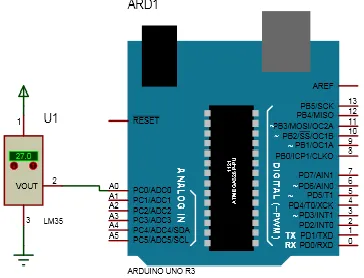
D. Temperature Sensor Unit (LM35)
[image:3.612.338.587.142.304.2]The drying compartment has a thermal sensor (LM35) mounted within it to take measurement of the temperature within the drying chamber. This measured temperature provides the information needed by the microcontroller to maintain the temperature of the drying compartment at its set point. This is achieved by turning OFF the heating element and turning ON the fan so that the temperature can be maintained at its set points by switching ON/OFF the heat source and fan as at when due. For a good temperature control, it is important that the choice of thermal sensor be very accurate and precise. LM35 is an integrated circuit temperature sensing device; it is a good choice because it is accurate, precise to about ±0.25oC and has a sensitivity of 10mV per degree Celsius. Also it can be easily interfaced with the ADC and hence the Arduino microcontroller for processing. Its range of operation is between -55oC to 150oC but in this work, it is used between ambient temperatures of 40oC and140oC as shown in fig .3.5.
[image:3.612.73.235.257.393.2]Fig. 3.4a: Design Circuit diagram of the LCD
[image:3.612.49.306.484.616.2]Fig. 3.4b: Led Connection to the Arduino Uno Board
Fig.3.3: The Arduino Uno Board with Microcontroller
[image:3.612.342.524.552.691.2]International Journal of Emerging Technology and Advanced Engineering
Website: www.ijetae.com (ISSN 2250-2459,ISO 9001:2008 Certified Journal, Volume 5, Issue 7, July 2015)
348
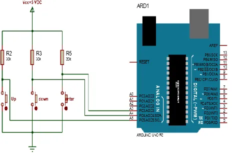
E. Switch Relay Unit
I. Pull-up Switches
In other to enter a set point into the Arduino, three pull-up switches were connected as shown in figure 3.6a. The state of port A3, A4, A5 of the Arduino pins will be high (1),
and when a user presses the push button switch it state changes to a low (0).
II. Bipolar Junction Transistor Switch
This unit consists of two bipolar junction transistors (NPN) used as a switch to either turn ON/OFF the heater or fan. The NPN (Q1) transistor is used to energies the relay
(RL1) when the base of the transistor receives a high sent
from the microcontroller, at this time; NPN (Q2) is
de-energized. When the temperature of the drying chamber equates the set point temperature, the microcontroller sends a low to the base of Q1, de-energizing RL1 and a high is
sent to the base of Q2, energizing relay RL2. When the
temperature of the drying chamber reduces below the set point, the microcontroller sends a low to the base of Q2,
de-energizing RL2 and it sends a high to the base of Q1,
energizing RL1. This turning ON and OFF of the control
switch is maintained until the drying chamber is switched OFF as shown in fig.3.6b.
F. MAX232 level converter
The MAX232 level converter is a converter that converts the Arduino TTL/CMOS signal level into RS232 standard. This enables communication to be established between the Seed dryer and a PC as shown in fig.3.7. The purpose for linking the circuit to a PC is to enable automatic data and logging, by storing these data in CSV format. It will enable easy analyses of results gathered during the drying process using software like Microsoft excel or MATLAB. Microsoft excel is the choice for this data analysis; since the circuit will be interfaced to a PC, a graphical user interface is developed in VB.net for data collection and display of the collected data on PC.
G. Heating Element
[image:4.612.324.561.145.296.2]The heating element is mounted at the base of the drying chamber, having 220V, 1500 watts rating. It is used to supply heat by radiation to the drying chamber during drying of seeds. The temperature of the heater is controlled by the Arduino, which controls the temperature of the heater from exceeding the set point of the drying chamber. The temperature of the heating element can be set to a fixed point as desired by the operator.
[image:4.612.56.288.231.388.2]Fig.3.6a: Circuit Design of three Pull – Up switches
International Journal of Emerging Technology and Advanced Engineering
Website: www.ijetae.com (ISSN 2250-2459,ISO 9001:2008 Certified Journal, Volume 5, Issue 7, July 2015)
349
H. Analog-to-Digital Converter (ADC)
The analog to digital converter is used for converting the signal from the LM35 thermal sensor into a digital signal that the Arduino controller can process. It is a specialized input pin of the Arduino Uno board. It uses an 8 bit successive approximation type of ADC for this conversion. The converted bits are stored within the memory of the controller for processing and display on the 16X2 LCD screen. The analog signal of the thermal sensor (LM35) is received at the input port of the ADC of the Arduino controller, converted and processed within the Arduino memory. The processed data is displayed on the LCD screen and is also captured on the PC through MAX 232 using VB.net programming codes.
I. Humidity Sensor (DHT11)
The choice of sensor used in the drying chamber is the DHT11 Humidity Sensor. It is a 2 in 1 sensor capable of measuring the relative humidity of the drying chamber to 100% relative humidity range; it also takes measurement of the temperature to a maximum value of 50oC. It will only be applied here as a humidity sensor. Data collected from the DHT11 is a 40 bit digital pulses that contains the temperature and humidity reading. It is captured by the input output (IO) port of the Arduino and the data for the relative humidity is displayed on a 16X2 LCD screen. When the temperature within the heating compartment is built up, the relative humidity rises to a certain level and then falls as temperature changes within the drying chamber.
This process continues until when the temperature maintains a steady rising, and then the humidity maintains a progressive fall. The relative humidity measured is processed within the microcontroller until it reaches the set point. At this point, the heater switches OFF, the red LED turns ON and the alarm beeps to alert the drying chamber operator. Unlike the thermal sensor, the DHT11 produces a digital signal which is processed directly by the Arduino as shown in fig.3.8.
J. Electric Fan
The fan is installed within the drying chamber just above the gauze tray. It is rated 12V Dc, 2 watts. The electric fan provides air circulation within the drying chamber. It helps hot air within the drying chamber to escape through the vent. At the vent, it provides sufficient moist air to the humidity sensor to measure the relative humidity present within the drying chamber. It also helps to keep the temperature within the drying chamber constant. When the temperature exceeds the set point, the fan turns ON and the heater turns OFF to ensure that the temperature of the drying chamber is brought below the set point value, and the fan turns OFF as the heater turns ON when the temperature goes below the set point.
K. Buzzer
This unit is designed to give an audible sound at the completion of the seed drying process. It is turned ON by a relay.
L. Seed Dryer Algorithm
[image:5.612.44.283.137.348.2]The choice of embedded chip for the temperature and humidity control system is in the Arduino Uno board.
[image:5.612.322.544.246.401.2]International Journal of Emerging Technology and Advanced Engineering
Website: www.ijetae.com (ISSN 2250-2459,ISO 9001:2008 Certified Journal, Volume 5, Issue 7, July 2015)
350 It uses a simplified version of Embedded C language for on chip programming of the Arduino Uno board through its integrated development environment (IDE). Also at the PC, the data is sent from the embedded system serially through the MAX232 chip and serially to USB cable, displayed and saved by a program written in VB.net. This gave rise to two different Algorithms for the two different programs developed as listed below:
I. Algorithm for the temperature and humidity control
system
1) Declare all pins to be used and declare variables type.
2) Initialize 16 x 2 LCD screen and display temperature set point on the screen.
3) Monitor the button Up, Down and Enter for low input to Arduino.
4) If Up is low increment set point and display on LCD screen.If Down is low decrement set point and display.
5) Declare all pins to be used and declare variables type.
6) Initialize 16 x 2 LCD screen and display temperature set point on the screen.
7) Monitor the button Up, Down and Enter for low input to Arduino.
8) If Up is low increment set point and display on LCD screen.
9) If Down is low decrement set point and display on LCD screen.
10) If Enter is low store set point in memory
11) Display ‗enter relative humidity and set point on LCD screen‘.
12) If Up is low increment set point and display on LCD screen.
13) If Down is low decrement set point and display on LCD screen.
14) If Enter is low store set point of relative humidity in Arduino memory and turn on green LED. 15) Read analogue data of the temperature from ADC
A0, store on Arduino Uno and Display on LCD screen.
16) from relative humidity sensor, store on Arduino Uno and Display on LCD screen.
17) Send stored temperature and relative humidity through the serial port to PC for display.
18) Check if temperature is greater than or equal to set point, if false turn on heater and turn off fan. 19) Check if temperature is greater than or equal to set
point, if true turn off heater and turn on fan. 20) If relative humidity is lesser than or equal to set
point, if false maintain previous state of heater and fan.
21) If relative humidity is lesser than or equal to set point, if true turn off heater and fan entire and turn on red LED to indicate that seed is fully processed.
II. Algorithm for Temperature and Humidity Control
System and the PC Graphical User Interface
1) Import input and output port for serial communication
2) Declare variables for temperature, relative humidity, temperature set point and relative humidity set point
3) Set Com Port, open CSV file and create write heading; Temperature, Relative Humidity, Temperature set point, Relative Humidity set point 4) Close file
5) Select Com Port 6) Set parity bit to none 7) Set stop bit to 1 8) Set data bit to 8 9) Open serial port
10) Receive 3 byte data after A is received and stored as Temperature
11) Receive 3 byte of data and store as relative humidity after B is received
12) Receive 3 byte of data and store as Temperature Set Point after C is received
13) Receive 3 byte of data and store as Relative Humidity Set Point after D is received
14) Open file
15) Write file to desktop 16) Close file
International Journal of Emerging Technology and Advanced Engineering
Website: www.ijetae.com (ISSN 2250-2459,ISO 9001:2008 Certified Journal, Volume 5, Issue 7, July 2015)
351 IV. RESULTS AND DISCUSSION
The drying chamber has a drying tray dimension of 18 inches by 14 ¼ inches with 4 inches depth, which can contain 700 seeds of melon, over a thousand of seed of tomato , about 200 seeds of fluted pumpkin, about 700 seeds of corn, beans and above a thousand seed of rice grains. Upon the drying tray is laid with aluminium foil to prevent the seed from having direct heat transfer through the wire mesh, hence, destroying the seeds. The wood used for the drying chamber is a fibre wood which can withstand temperature of about 800 degree Celsius to 1000 degree Celsius.
A. Testing the Temperature and the Relative Humidity of
the seeds within the Drying Chamber
The circuit designed to control temperature and humidity was installed on the top right side of the drying chamber, with the sensors inserted above the gauze tray of the seeds. The set points of both temperature and relative humidity were entered into the device with the push buttons on the circuit, thus, marking the start of the drying process of the seeds. After this is done, the drying process begins by the system turning ON the heating element. The heat generated is used to build up the temperature within the drying compartment, as this is required by the seeds for the reduction of its moisture content. As the temperature increases progressively within the drying chamber, heat transfer between the heating element and the seed is by radiation from the heating element and conduction resulting from the seed contact with the gauze.
With this heat transfer from the heating element to the seeds, moisture (water vapour) evaporates from the seeds and escape to the surrounding air, as a result, altering the relative humidity of the drying chamber. This altered value is assumed to be the humid content of the seed. This modified relative humidity within the drying chamber as a result of the vaporization of water from the seed is captured by the relative humidity sensor (DHT11).
As the drying process progresses, and the temperature within the drying chamber rises above the set temperature, the system de-energizes the relay controlling the heating element, and the relay controlling the fan turns ON the fan. At this point the temperature within the drying chamber remains constant for a few second before it drops below the set point where the relay becomes energized again and then turns ON the heater. This process continues until when the relative humidity reduces below its set point, the entire process stops, triggers the alarm, the heating element turns OFF and the fan remains in its OFF position.
When the relative humidity rises above its set point, the heating element turns ON and the drying process begins again. The measured data obtained from the drying process is automatically logged onto a CSV file and is saved automatically on excel file. This process continues until the user or the operator is satisfied with percentage of the moisture content left within the seed obtained from the drying process.
B. Discussion on the results obtained from Drying of Seeds using seed dryer
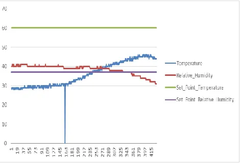
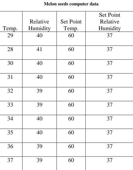
1) Melon Seeds: The values of temperature and relative
[image:7.612.323.558.303.464.2]humidity obtained from drying of melon seeds is plotted as shown in Figure 4.1 and parameters shown in table 3.1
Fig.4.1: Relationship between Temperature and Relative Humidity for Melon Seeds
International Journal of Emerging Technology and Advanced Engineering
Website: www.ijetae.com (ISSN 2250-2459,ISO 9001:2008 Certified Journal, Volume 5, Issue 7, July 2015)
[image:8.612.323.571.127.261.2]352 This process continued till the moisture in the seed reduced to a minimal level and the system was finally turned OFF.
Table 3.1: Melon seeds computer data
2) Pumpkin Seeds: The initial temperature was measured at 51 degree Celsius and the initial value of relative humidity was measured at 35 precent, and the set points for Temperature and Relative Humidity were 61 degree Celsius and 18 precent respectively. The graph is shown in fig.4.2. Table 3.2 shows the pumpkin seeds computer generated data.
Figure 4.2 above shows the relationship between temperature and relative humidity for pumpkin seeds as measured and controlled within the seed drying chamber. The initial temperature was measured at 27 degree Celsius and the initial value of relative humidity was measured at 65 precent.
Fig. 4.2: Relationship between Temperature and Relative Humidity for Pumpkin Seeds
[image:8.612.46.274.182.473.2]When the temperature got to the set point of the seed dryer, the relay 1 turned OFF the heater and the fan was turned ON by relay 2 till the temperature reduced below the set point value. At reduced temperature, the relative humidity within the drying chamber increased and was decreased when the temperature was high again. This process was maintained till the moisture in the seed reduced to a minimal level and the system was finally turned OFF.
Table 3.2:
Pumpkin seeds computer data
Temp.
Relative Humidity
Set Point Temp.
Set Point Relative Humidity
29 40 60 37
28 41 60 37
30 40 60 37
31 40 60 37
32 39 60 37
33 39 60 37
34 40 60 37
35 40 60 37
36 39 60 37
37 39 60 37
Temp.
Relative Humidity
Set Point Temp.
Set Point RelativeHumidity
50 34 61 18
51 35 61 18
52 32 61 18
53 32 61 18
54 30 61 18
55 30 61 18
56 29 61 18
57 29 61 18
58 24 61 18
[image:8.612.338.570.428.692.2]International Journal of Emerging Technology and Advanced Engineering
Website: www.ijetae.com (ISSN 2250-2459,ISO 9001:2008 Certified Journal, Volume 5, Issue 7, July 2015)
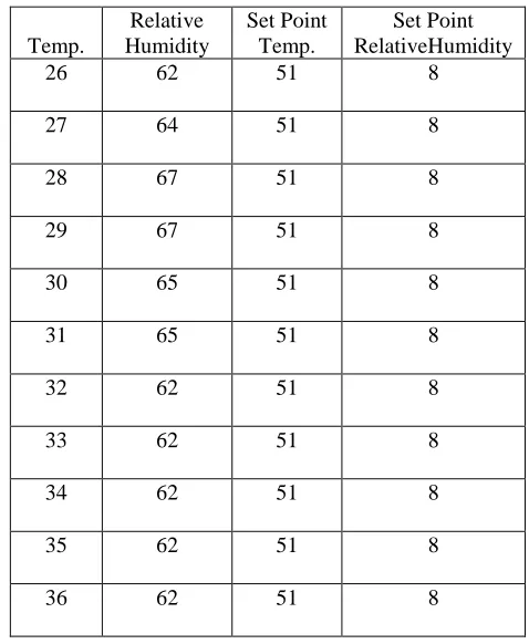
[image:9.612.332.571.160.451.2]353 3) Tomato Seeds: The initial temperature was measured at 26 degree Celsius and the initial value of relative humidity was measured at 62 percent, and the set points for Temperature and Relative Humidity were 51 degree Celsius and 8 percent respectively as shown in table 3.3. The graph of data plotted is shown in fig.4.3.
Fig.4.3: Relationship between Temperature and RelativeHumidity for Tomato Seeds
Figure 4.3 below shows the relationship between temperature and Relative humidity for Tomato seeds as measured and controlled within the seed drying chamber. The initial temperature was measured at 26 degree Celsius and the initial value of relative humidity was measured at 62 percent. At the initial stage, when the heater was on, the temperature of the dryer increased progressively until it reached the temperature set point, while the relative humidity was at a high percent value. When the temperature was high, the relative humidity was low. When the temperature got to the set point of the seed dryer, the relay 1 turned OFF the heater and the fan was turned ON by relay 2 till the temperature reduced below the set point value. At reduced temperature, the relative humidity within the drying chamber increased and was decreased when the temperature was high again. This process was maintained till the moisture in the seed reduced to a minimal level and the system was finally turned OFF
Table 3.3: Tomato seeds computer data
C. Graphical User Interface for Real time data acquisition
The Graphical user interface for capturing the temperature and humidity readings was developed in Visual studio as shown in fig. 4.4
Temp.
Relative Humidity
Set Point Temp.
Set Point RelativeHumidity
26 62 51 8
27 64 51 8
28 67 51 8
29 67 51 8
30 65 51 8
31 65 51 8
32 62 51 8
33 62 51 8
34 62 51 8
35 62 51 8
[image:9.612.37.294.205.389.2]36 62 51 8
[image:9.612.322.572.507.673.2]International Journal of Emerging Technology and Advanced Engineering
Website: www.ijetae.com (ISSN 2250-2459,ISO 9001:2008 Certified Journal, Volume 5, Issue 7, July 2015)
354 When the system is operating, the temperature and humidity are captured through the serial port of the system and displayed in the GUI interface as shown in fig 4.4 above. The data captured is logged into Microsoft Excel for further analysis and use.
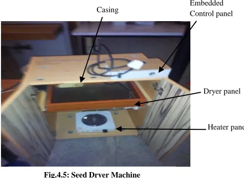
D. Implemented Seed Dryer Machine for Farm Produce
Figure 4.5 below is a typical seed dryer machine designed for quick drying of fresh farm produce. It consists of the heater, dryer tray and embedded control panels. The wooden casing was used to cover the various panels. It uses normal regulated +5V DC supply.
The operation is very simple and easy to use. When the power cord of the system is plugged in 230V AC mains and powered, the embedded control panel is energized and the display panel comes ON. The Laptop is connected to the system for data acquisition through serial port via USB port of the embedded control panel. The user must ensure that his/her laptop has installed Visual Basic studio to access the GUI interface. The seed to be dried should be spread on the dryer tray panel. As soon as the connections are properly done, the temperature and humidity of the system will be captured and logged into computer Microsoft Excel via serial port. The values of the temperature and humidity captured are displayed on the LCD panel and GUI interface program of the Laptop system. During the system operation, the embedded control panel monitors the temperature and humidity of the system being generated and adjusts for effective seed drying. When the drying is done, an alarm panel is activated to draw the attention of the user and the system shuts down after some stipulated time.
Parts of the GUI interface and data acquisition codes for the system are written in Visual Basic as shown below:
'Serial Port Interfacing with VB.net 2010 Express Edition 'Designed by:
Imports System
Imports System.ComponentModel
Imports System.Threading
Imports System.IO.Ports
PublicClassfrmMain
Dim myPort As Array 'COM Ports detected on the system will be stored here
Delegate Sub SetTextCallback(ByVal [text] As String)
'Added to prevent threading errors during receiveing of data
Dim count AsInteger = 0 Dim x AsChar
Dim a AsString = "" Dim b AsString = "" Dim c AsString = "" Dim d AsString = ""
Dim Temperature AsString = "" Dim Relative_Humidity AsString = "" Dim Set_Point_Temperature AsString = "" Dim Set_Point_Relative_Humidity AsString = "" Dim setpoint AsString
Dim n AsDouble
Private Sub frmMain_Load(ByVal sender As
System.Object, ByVal e As System.EventArgs) Handles MyBase.Load
'When our form loads, auto detect all serial ports in the system and populate the cmbPort Combo box.
myPort = IO.Ports.SerialPort.GetPortNames() 'Get all com ports available
cmbBaud.Items.Add(9600) 'Populate the cmbBaud Combo box to common baud rates used
cmbBaud.Items.Add(19200) cmbBaud.Items.Add(38400) cmbBaud.Items.Add(57600) cmbBaud.Items.Add(115200) For i = 0 To UBound(myPort) cmbPort.Items.Add(myPort(i)) Next
cmbPort.Text = cmbPort.Items.Item(0) 'Set cmbPort text to the first COM port detected
cmbBaud.Text = cmbBaud.Items.Item(0) 'Set cmbBaud text to the first Baud rate on the list
btnDisconnect.Enabled = False 'Initially Disconnect Button is Disabled
[image:10.612.53.301.282.463.2]Dim file As System.IO.StreamWriter
Fig.4.5: Seed Dryer Machine
Embedded Control panel
Dryer panel
International Journal of Emerging Technology and Advanced Engineering
Website: www.ijetae.com (ISSN 2250-2459,ISO 9001:2008 Certified Journal, Volume 5, Issue 7, July 2015)
355
file =
My.Computer.FileSystem.OpenTextFileWriter("C:\Users\
USER\Desktop\SeedDryingLogger.csv", True)
file.WriteLine("Temperature" & "," & "Relative_Humidity" & "," & "Set_Point_Temperature" & "," & "Set_Point_Relative_Humidity")
file.Close()
EndSub
Private Sub btnConnect_Click(ByVal sender As
System.Object, ByVal e As System.EventArgs) Handles
btnConnect.Click
SerialPort1.PortName = cmbPort.Text 'Set SerialPort1 to the selected COM port at startup
SerialPort1.BaudRate = cmbBaud.Text 'Set Baud rate to the selected value on
'Other Serial Port Property
SerialPort1.Parity = IO.Ports.Parity.None SerialPort1.StopBits = IO.Ports.StopBits.One SerialPort1.DataBits = 8 'Open our serial port
SerialPort1.Open()
btnConnect.Enabled = False 'Disable Connect button
btnDisconnect.Enabled = True 'and Enable Disconnect button
EndSub
Private Sub btnDisconnect_Click(ByVal sender As
System.Object, ByVal e As System.EventArgs) Handles
btnDisconnect.Click
SerialPort1.Close() 'Close our Serial Port
btnConnect.Enabled = True
btnDisconnect.Enabled = False
EndSub
Private Sub btnSend_Click(ByVal sender As
System.Object, ByVal e As System.EventArgs) Handles
btnSend.Click
SerialPort1.Write(txtTransmit.Text) ' & vbCr) 'The text contained in the txtText will be sent to the serial port as ascii
'plus the carriage return (Enter Key) the carriage return can be ommitted if the other end does not need it
EndSub
Private Sub SerialPort1_DataReceived(ByVal sender As
Object, ByVal e As
System.IO.Ports.SerialDataReceivedEventArgs) Handles
SerialPort1.DataReceived
ReceivedText(SerialPort1.ReadExisting())
'ReadExisting()) 'Automatically called every time a data is received at the serialPort
EndSub
V. CONCLUSION
The Temperature and Humidity Control system applied in Seed Dryer is a very good replacement for the conventional way of drying seeds especially during wet season. It is a dynamic system which can be controlled as desired by the user. Its application is suitable for drying any consumer product processed from the farm. The system is reliable, flexible and very efficient.
The heating element of this system is rated at 1500 Watts of electricity which would require a bigger generator above the wattage of the heating element for its effective operation; a disadvantage to farmers who cannot afford such unit. For an average farmer to be able to utilize this system with the resources made available in his environment, the heating element could be replaced with 100 watts or 200 watts incandescent bulb which could produce the same heating effect as produced by the heater.
REFERENCES
[1] Chuck C., Chris C., Loren J., David A., Carrie K., Curtis R., Janie C. 2015, ―History of seed drying – Cornelius seed‖, http://www.corneliusseed.com/about-history.html
[2] Gurmeet S., Jarial K., Anshul A.l, Satyaprakash R., Mithun M., Suresh K. D. 2012. ―Sequence Control of Grain Dryer Machine using PLC‖ IOSR - Journal of Electrical Electronics Engineer Vol 3, p 33, 40
[3] Paul J. D., Harvey M. D. 2011. Visua Basic 2010, Prentice hall, 2011
[4] Samuel G. M., Michael D. M. 2001. ―Harvesting, Drying and Storing Grain Sorghum‖, Cooperative Extension Service AEN-17, p 2-3
[5] Stephaine B. 2011. A beginner‘s guide to humidity measurement, Guide No. 124, Queen‘s Printer and Controller of HMSO, pp 2, 5, 17
[6] Victor M., Carlos B., Ruiz-Ruiz J. G., Luis M. N., Javier M. C. Aguiar,B.G. 2012, ―Temperature and Relative Humidity Estimation and Prediction in the Tobacco Drying Process Using Artificial Neural Networks‖, Sensors Vol 12 p 1-5
[7] Vincent A. F., Harold A. C., Robert F. D., Alicia M. B. 1990, ―A Versatile Heat Pump Seed Dryer‖, HORTSCIENCE VOL. 25 (8), p 977-978
[8] Electronic Components datasheet, www.datasheet.com