Microstrip Patch Antenna Design by Using
Hybrid FEM-FDTD Computational
Techniques
Abstract - In the last few years, there has been an increasing demand for designing multiband antennas for cellular communication devices. In particular, the focus has been on internal antenna designs. With the third generation (3G) wireless communication systems introduced world-wide, the demand to support both old and new standards using a single mobile phone becomes compulsory. Therefore, the most immediate task for the new antenna is to operate at both new UMTS frequency bands and already established 2G frequency bands. In addition, there is also a requirement on mobile phone to serve some new wireless communication applications, including WLANs and Bluetooth.
In this paper, a new compact microstrip patch antenna designed to operate at three main communications frequency bands (GSM, UMTS and Bluetooth) with a single feed are presented. The antenna is designed on thick air substrate. The antenna is mounted on top of finite ground plane that can be considered as a circuit board of practical mobile phones.
The antenna are simulated and optimised for best operation using FEMLAB designer and their performance are measured and compared. A comparison between measurement and simulation is presented and show a good agreement.
I INTRODUCTION
The FEM is already widely and successfully used in computation of static and quasi-static electric and magnetic fields at DC and low (<1 kHz) frequencies, and for enclosed systems (waveguides, cavities etc) at high frequencies [2]. However, there have been problems in applying the method to high-frequency open-field (radiation and scattering) problems for reasons that are in need of investigation. The finite-difference time-domain (FDTD) scheme [3] is very popular for electromagnetic modelling because of its simplicity and efficiency. One drawback of the FDTD is the staircase approximation of oblique boundaries, which often gives poor accuracy. The finite-element method (FEM) allows good approximations of complex boundaries and with edge elements it performs well for Maxwell’s equations [4]. However, FEM requires more memory and has a higher operation count than the FDTD. An obvious remedy is a hybrid that applies FDTD in large volumes, combined with FEM near complex boundaries. Previously attempted hybrids of
this type [5,6] suffer from instabilities known as late time growth.
The modified equivalent surface with one or more faces was replaced by a conducting surface was investigated (see Fig. 1). In this modification, the conducting surface can be extended beyond the size of the equivalent surface such as the handset box excluding the antenna part of the mobile phone. Normally, the frequency domain FEM was used to analyse a structure up to a few wavelengths in size and it is particularly appropriate for simulation of 1-D, 2-D and 3-D structures. However, it faces some difficulties to manage substantial volume of dielectric since the size of the interaction matrix become larger when the number of quantisation elements exceeds a few thousands. By the way, FDTD can handle substantial penetrable dielectric and partially-conducting structures such as human head since each quantisation element interacts only with its nearest neighbours and not with the entire set of elements [7].
The basic idea of the FEM-FDTD hybridisation technique has been realised in the recent past and it has been extensively studied and tested in different application [8,9]. The coupling between these methods is compute by using the equivalent principle theorem. The objects are not connected in physical manner but only separated by a small distance, sufficiently to permit the equivalent principle surface to place in isolation between them.
Figure1. Basic geometry of the modified hybrid method.
Rozlan Alias
Communication Engineering Department, Faculty of Electrical & Electronics Engineering,
Universiti Tun Hussein Onn Malaysia Batu Pahat, Johore, Malaysia
Equivalent surface currents
FDTD Problem space Conducting surface
Scatterer
In this paper, a air substrate microstrip antenna has been chosen for evaluation purposes since it is the most familiar antenna used in mobile handset now days. The antenna is small, compact and can be mounted on one side of the Mobile handset and easily altered depends on the manufacturer needs. The antenna including the finite ground plane has been modelled by using the FEMLAB software that uses FEM principles. Firstly, the equivalent surface boundary has been chosen at the edges of the finite ground plane (see Fig. 2) and then the size of equivalent surface was modified and the antenna performance was predicted with and without presence of the scatterer. Finally, for the hybridisation process the equivalent surface and the finite ground were inserted inside the FDTD code as shown in Fig. 1. Figure 2 shows the geometry and dimensions of the thick air substrate antenna for a dual-band frequencies mobile phone. The antenna was designed first and then was mounted on top of a finite ground plane with dimension of 8 x 5 cm2. The radiating patch consists of single patch. A 50-Ω SMA probe connector with radius 0.5 mm placed perpendicular to the ground plane, through which a coax is used H field excitation. The antenna is supported by two different size of shorted pins of height of 11 mm from the ground plane with the radius 0.5 mm and 2 mm, respectively. By introducing a long slit in the middle of the patch, the lower resonant frequency can be easily controlled. It should be noted that feeding strip line arranged at one side of the patch can generate combined dual-resonance naturally, whose operating frequencies can be shifted by changing the length and width of the patch. In addition, a probe feed, at the bottom edge of the strip line, can be located for good excitation of the antenna over resonant frequency bandwidths.
Figure 2. Geometry of air substrate microstrip antenna handset.
II SUMMARY OF THE METHOD
Using the surface equivalent theorem, the near-to-near and near-to-far field transformation can be extended through using FEM to FDTD modelling of 3-D scatterers and antennas. Consider Fig. 1, the fields outsides of the equivalent closed surface are obtained by placing suitable electric and magnetic current densities that satisfy the boundary conditions. The current densities are selected so that the fields inside the closed surface are zero and outside are equal to the radiation produced by the actual sources. The degree of
accuracy depends on the knowledge of the tangential components of the fields over the closed surface. Figure 1 represents schematically the most general case dealing with electromagnetic wave interactions with an arbitrary 3-D structure. It is assumed that a field (E1,
H1) filling all of space is generated by the action of
physical electric and magnetic current sources J1 and
M1 flowing on the surface structure of interest. There
are now exists a new field (E, H) inside an arbitrary closed observation surface S that completely encloses the structure. The original (E1, H1) will be observed
outside S. The following non-physical electric and magnetic currents flowing tangentially along S must be exist to satisfy the desired situation of the field boundary conditions. Thus:
JS = -n x (H1 – H) (1)
MS = n x (E1 – E) (2)
Where n is the unit outward normal vector to S. Js and
Ms are the surface electric and magnetic currents. Now,
the current densities can be simplified as in following: JS = -n x (H1 – HH=0) = n x H1 (3)
MS = n x (E1 – EE=0) = -n x E1 (4)
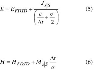
The currents on surface boundary (that exclude the conducting surface currents on the handset) can be transferred to FDTD method by treating them as impressed currents. These impressed sources can be represented through the FDTD difference equations as follows: 2 t J E
E FDTD sS (5)
t M H
H FDTD sS (6)
The conducting surface (finite ground or handset) will be directly modelled through the FDTD method. However, the procedure can be extended on two or more conducting surface enclosed within the equivalent surface. In general, due to the structure of non-uniform meshing (normally tetrahedral cells) used in FEM and uniform cells distribution (ex. rectangular cells) of FDTD, a support program was written to link these field points that exist on the equivalent surface.
III SIMULATION AND RESULTS
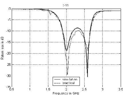
[image:2.595.86.292.478.587.2]simulation results are obtained by using Femlab 3.0 (FEM) simulation software. An experiment also has been done to confirm the validity of the results. From the result obtained, it shown a good agreement for both simulation package and from the experiment. The radiation pattern or far field are been shown in Figure 5 with 20-30 dB radiation. A Fortran-90 program was written in which that simulates the details gave in previous section. The operating frequency was chosen at 1800 MHz and the handset dimension (finite ground) was 5 cm x 8 cm. The antenna was properly designed with minimum return loss at 1800MHz and 9% relative bandwidth at 10dB. FEM problem space for all presented examples was considered 12cm x 9cm x 4cm and the method uses low reflecting boundary. The antenna was excited by magnetic frill through a coaxial cable of radius 2.5 mm. The FDTD cell size and the time step were 2.5mm and 3.375ps respectively. Number of the FDTD PML (perfect matching layer) cells was 6. Several examples were presented as follows:
Input Impedance (Ohm)
-300 -200 -100 0 100 200 300 400 500 600 700
0.5 1.5 2.5 3.5
Frequency (GHz) In
pu t Im pe da nc e (O h m)
[image:3.595.357.501.36.694.2]Resistance Reactance
Figure 3. Input Impedance
Figure 4. Simulated and measured Return loss of the antenna
(a) x-y plane (simulation)
(b) y-z plane (simulation)
(c) x-y plane (experiment)
(d) y-z plane (experiment)
Figure 5. Radiation pattern by using Femlab (fig. (a), (b)) and Experiment (fig. (c) and (d)).
[image:3.595.79.304.325.513.2] [image:3.595.88.303.562.727.2]to 32 x 20 x 12 cells inside the FDTD problem space. The FDTD problem space dimension was 54 x 54 x 38 cells. The field contours without the scatterer for two different cuts inside the FDTD problem space are shown in Fig. 6. A shown the difference between the total field and the scattered fields was 25 to 30 dB that is quite reasonable with the expectations.
(a)
[image:4.595.324.532.53.288.2](b)
Fig. 6. Field contours for Fig. 2a at: (a) yz plane, (b) xz plane.
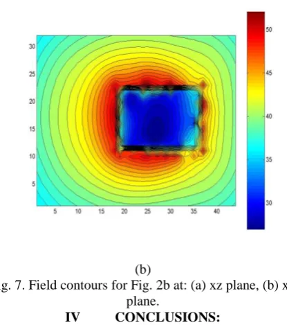
Example 2: The equivalent surface size encloses the radiating part of the antenna was set up to be 3cm x 4cm x 3cm (equivalent to 12 x 16 x 12 cells inside the FDTD method) as shown in Fig. 2b. The FDTD problem space dimension was same as the previous example. The field contours without the scatterer for two different cuts inside the FDTD problem space are shown in Fig. 7. A shown the difference between the total field and the scattered fields was similar to that observed in the previous example. However, the memory locations for the field points on the boundary were reduced by 70% compared to the first example.
(a)
(b)
Fig. 7. Field contours for Fig. 2b at: (a) xz plane, (b) xy plane.
IV CONCLUSIONS:
Hybridisation technique between the FEM and FDTD to design new compact microstrip antenna has been presented. Equivalent surface including a conducting surface was successfully implemented through the boundary that coupled the two methods. A reduced equivalent surface was presented and was found sufficient to predict the antenna performance with and without scattterer. This save 70% of the required memory locations of the field points between the two domains and also speed up the updating boundary equations inside the FDTD method. The results are stable and show a good agreement with different technique.
ACKNOWLEDGMENT
I would like to take this opportunity to express my gratitude to my colleagues and departmental technical staff for their technical support from the beginning to the end of the research. The financial support provided by my employer, Universiti Tun Hussein Onn Malaysia is gratefully acknowledged.
REFERENCES
1. R. Alias, R.A.Abd Alhameed, P.S. Excell ‘A Conducting Domain Surface Boudary Applied to Hybrid FEM-FDTD Electromagnetic Models’, International Journal of Advanced Computer Science 2012, Vol. 2, No. 10, Oct. 2012, pp. 382-384.
2. Rozlan Alias, ‘Simulation of Radiation Performance for Mobile Antennas using a Hybrid FEM-FDTD Computational Technique’ Fourth International Conference On Modeling, Simulation And Applied Optimization 2011 (ICMSA0’2011), 19-21 April 2011, Kuala Lumpur, Malaysia.
[image:4.595.86.281.145.471.2]4. Rozlan Alias, ‘Modified Equivalent Boundary Surface Principles using Hybrid FEM-FDTD Electromagnetic Models’ International Conference on Mathematical Applications in Engineering (ICMAE2010), 3-4 August 2010, Kuala Lumpur, Malaysia.
5. R. Alias, R.A. Abd-Alhameed and P.S. Excell, “A Modified Equivalent Conducting Surface Boundary using the Hybrid FEM-FDTD Technique”, 8th IEEE International Multi-topic conference (INMIC2004), Lahore, Pakistan, pp. 698-702, December 24-26, 2004. 6. J.L. Volakis, T. Ozdemir, J. Gong, ‘Hybrid Finite-Element Methodologies For Antennas And Scattering’, IEEE Trans. Antenna Propagat., Vol. 45, pp. 493-505, 1997.
7. A. Taflove, S.C. Hagness: ‘Computational Electrodynamics: The Finite-Difference Time-Domain Method’, Artech House Inc. 2000.
8. J. Jin, The Finite Element Method in Electromagnetics, New York: John Wiley & Sons Inc, 1993.
9. R.B. Wu and T. Itoh, “Hybrid finite-difference time-domain modeling of curved surfaces using tetrahedral edge elements,” IEEE Trans. Antennas Propagat., vol. 45, pp. 1302–1309, Aug. 1997.
10. A. Monorchio and R. Mittra, “A hybrid finite-element finite-difference time-domain (FE/FDTD) technique for solving complex electromagnetic problems,” IEEE Microwave Guided Wave Lett., vol. 8, pp. 93–95, Feb. 1998.
11. M.A. Mangoud, R.A. Abd-Alhameed, P.S. Excell: ‘A Heterogeneous Hybrid Computational Electromagnerics Formulation Including Conduction Current Crossing the Domain Boundary’, ACES Journal, Vol. 16, No. 2, July 2001, pp. 155-161. 12. T. Rylander and A. Bondeson: ‘Application of Stable FEM-FDTD Hybrid to Scattering Problems’, IEEE Transactions on Antennas and Propagation, Vol. 50, No. 2, Feb. 2002, pp. 141-144.
13. T. Rylander, P. Ingelström and A. Bondeson, ‘Application of stable FEM-FDTD hybrid to scattering and antenna problems’, Conference Proceedings, on Antennas, September 12-14, 2000, Lund, Sweden, pp. 75-82.
14. P.S. Excell, ‘Computer modelling of high frequency electromagnetic field penetration into the human head’, Measurement and Control, Vol. 31, No.