Journal of Magnetics 20(3), 265-272 (2015) http://dx.doi.org/10.4283/JMAG.2015.20.3.265
©2015 Journal of Magnetics
Analysis of High Torque and Power Densities Outer-Rotor PMFSM with
DC Excitation Coil for In-Wheel Direct Drive
M. Z. Ahmad1,2*, E. Sulaiman1,2, and T. Kosaka3
1Faculty of Electrical and Electronic Engineering, Universiti Tun Hussein Onn Malaysia, Johor Malaysia 2Reseacrh Center for Applied Electromagnetics, Universiti Tun Hussein Onn Malaysia, Johor Malaysia
3Dept. of Electrical and Computer Engineering, Nagoya Institute of Technology, Nagoya, Japan
(Received 26 March 2015, Received in final form 6 August 2015, Accepted 19 August 2015)
In recent years, flux switching machines (FSMs) have been an attractive research topic owing to their tremendous advantages of robust rotor structure, high torque, and high power capability suitable for intensive applications. However, most of the investigations are focusing on the inner-rotor structure, which is incongruous for direct drive applications. In this study, high torque and power densities of a new 12S-14P outer-rotor permanent magnet (PM) FSM with a DC excitation coil was investigated based on two-dimensional finite element analysis for in-wheel direct drive electric vehicle (EV). Based on some design restrictions and specifications, design refinements were conducted on the original design machine by using the deterministic optimization approach. With only 1.0 kg PM, the final design machine achieved the maximum torque and power densities of 12.4 Nm/kg and 5.93 kW/kg, respectively, slightly better than the inner-rotor HEFSM and interior PM synchronous machine design for EV.
Keywords :dual excitation flux, outer-rotor, flux switching machine, Direct drive
1. Introduction
In the 21st century, global warming is one of the major issues discussed all over the world by scientists and government agencies. The major factor that contributes to the global warming is the greenhouse effect, because of the human activities, heat by solar radiation, and geo-magnetic variation [1]. As reported previously [2], the burning of fossil fuels is one of the main contributors to the global warming issue by means of conventional internal combustion engine (ICE) vehicles. Because the price of fossil fuel is increasing year by year, lots of researcher and industries are looking for electric vehicles (EVs) as the most possible solution for transportation [3]. Thus, the commercialization of EV may dramatically decrease the air pollution and will meet the world energy strategy to seek for an energy future that would be secure, efficient, and environmentally sound [4].
In general, the propulsion system for conventional EVs comprises batteries, electric motors with drives, and
trans-mission gears to the wheels. This configuration leads to torque and power loss in the transmission system, thus decreasing the electric motor’s efficiency. Moreover, it consumes a lot of space to locate the transmission and gearing system in vehicle’s cabin that increase the total vehicle weight. Therefore, in-wheel direct drive motor is an alternative model for EV, where the transmission system comprising gearing, belting, and mechanical system in the conventional EV can be eliminated. Thus, the transmission losses are minimized, and the operational efficiency and reliability are improved [5]. Moreover, more batteries can be installed in the space that would be occupied by the transmission system, which will help to increase the driving range per charge. In contrast, because of the elimination of gears, the system needs to produce the total torque directly into the wheel shaft with higher torque and power density as compared to that in the conventional EV [6, 7].
Electric motors with a high torque density capability must be used for heavy applications such as in aerospace and automotive area [8]. Previously, PM brushless machines are widely used for these heavy applications owing to their advantages of high torque density, high power den-sity, wide speed range, wide constant power, and high
efficiency capabilities [9, 10]. Nevertheless, because the main flux source of PMs is located on the rotor, the machines suffer from the demagnetization effects and eddy current loss in the rotor. Moreover, the difficulty to remove heat from the rotating part is among the major issues of this type of electric machine.
Almost a decade, flux-switching motors (FSMs) have been an attractive research topic owing to their several advantages of higher torque density and efficiency. With all the active components such as PM, DC field excitation coil (DC FEC), and armature coil located on the stator, the machine in which only a single piece of rotor iron is used becomes extremely robust. Various applications of FSM have been reported, ranging from wind power generation, automotive, aerospace, power tools and etc [11-14]. In general, FSMs can be classified into three groups, namely PM FSMs, hybrid excitation (HE) FSMs, and field excitation (FE) FSMs. Both the PMFSMs and FEFSMs have only single excitation flux source which either comes from the PM or FE coil, respectively, whereas in HEFSM there are two magnetic flux sources, which come from PMs and FECs [15].
However, to date, most of the designed FSMs are mainly focused on inner-rotor configurations [16, 19] and earliest report on the outer-rotor PMFSM was published in 2010 where the machine target is to be applied for light traction EV applications [20, 21]. Nonetheless, with a single magnetic flux source of a constant PM, it may also suffer from the demagnetization effect and uncontrollable flux.
This study presents an investigation and optimization study of 12S-14P outer-rotor PMFSM with DC FEC to meet the requirement of in-wheel direct drive EV. In this machine, the presence of FEC makes the machine more attractive especially for the modulating flux of PM. The existence of FEC provides an extra advantage to the machine, acting as the secondary flux source to improve the maximum torque and power capabilities, because of variable flux control capability. Initially, the feasibility study of the proposed machine was reported as discussed [22]. However, based on initial analysis using 2D-FEA, the proposed machines have several drawbacks that pre-vent them to achieve maximum performances especially at maximum current densities. To improve the design drawbacks, some design refinements and optimization were conducted by the deterministic optimization ap-proach. The outline of this study is divided into the following sections:
Section 2. Principle operation of the proposed machine Section 3 Investigation of the original design machine based on 2D-FEA of 12S-14P outer-rotor PMFSM with
the DC FEC configuration
Section 4. Methods of obtaining maximum performances based on FEA
Section 5. The final design and the optimal performances of the machine
Section 6. Conclusions
2. Principle Operation of Outer-Rotor
PMFSM with DC Excitation Coil
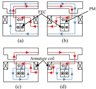
[image:2.595.325.530.531.721.2]The term “flux switching” was introduced to explain the fact that the excitation flux linkage switches its polarity by following the motion of the salient pole rotor. For details, the operating principle of the proposed outer-rotor PMFSM with DC FEC is illustrated in Fig. 1 where the upper part is the salient rotor core and the lower part represents the stator body comprising PM, armature wind-ing, and FEC winding. The excitation flux of the PM and FEC is indicated by red and blue lines, respectively. When the polarity and direction of both the flux of PM and FEC are the same as shown in Figs. 1(a) and 1(b), both fluxes are combined and moved together into the rotor, hence producing more flux called as the hybrid excitation flux. Furthermore, Figs. 1(c) and 1(d) show that the polarity of FEC is in the reverse direction and only the flux of PM flows into the rotor, whilst the flux of FEC just move around the FEC slot area, thus bring out less flux excitation. The flux does not rotate, but shifts clockwise and counter-clockwise with each armature current reversal. Therefore, the flux of PM can be easily controlled by DC FEC with variable flux control capabi-lities even under field weakening and field strengthening
Fig. 1. (Color online) Principle operation of outer-rotor
PMFSM with DC excitation coil; maximum excitation (a) θe =
conditions.
3. Original Design Performances Based
on 2D-FEA
3.1. Original Design Structure
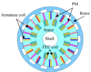
Initially, the proposed 12S-14P outer-rotor PMFSM with DC FEC was designed using the commercial FEA package, JMAG-Designer V.13 software. This software is used as the 2D finite element solver throughout the design studies. The original structure of the proposed machine is illustrated in Fig. 2, and the number of turns of the armature coil and FEC were investigated by Eq. (1).
and (1)
where subscripts ‘a’ and ‘e’ indicate armature coil and FEC components, respectively, N is the number of turns of coil winding, α is the filling factor, R is the coil resistance (Ω), S is the coil slot area (mm2), and L is the average coil length (mm). Furthermore, the current density of armature coil (Ja) and FEC (Je) are determined by Eq. (2). In this design, the material used for the conductor is SWG-24 copper with a diameter of 1 mm.
and (2)
The proposed machine comprises 24 stator teeth with alternate DC FEC, alternate PM flux direction, and counter clockwise armature coil slots around the stator body. The material used for the PM is NEOMAX-35AH whose residual flux density and coercive force at 20°C
are 1.2 T and 932 kA/km, respectively, and electromagnetic steel 35H210 was used for the rotor and stator core.
3.2. Design Restrictions and Specifications
The design restrictions and specifications of the pro-posed outer-rotor PMFSM with DC FEC are based on the inner-rotor HEFSM and IPMSM designed for HEV listed in Table 1 [19]. In this design, the target performances of the maximum torque and power were expected to be >333 Nm and 123 kW, respectively, under the maximum inverter current, voltage, armature current density, and FEC current density ratings of 360 Arms, 650 V, 30 Arms/ mm2, and 30 A/mm2, respectively. The target weight of the proposed motor was initially set to be at least 30 kg, which is 5 kg less compared to that of IPMSM. There-fore, it is expected that the proposed machine can achieve the maximum power and torque density of 11.1 Nm/kg
Na =
αaRaSa 4ρLa ave–
--- Ne = αeReSe 4ρLe ave–
---Ja =
IaNa
αaSa
--- Je = IeNe
αeSe
---Fig. 2. (Color online) Cross-sectional view of the original
[image:3.595.336.525.102.252.2]outer-rotor PMFSM with DC FEC.
Table 1. Design restrictions and specifications of the outer-rotor PMFSM with DC FEC.
Descriptions IPMSM Target Outer-Rotor
PMFSM with DC FEC
Max. DC-bus voltage inverter (V) 650 650
Max. inverter current (Arms) 360 360
Max. current density in armature coil, Ja (Arms/mm2) Conf. 30
Max. current density in FEC, Je (A/mm2) NA 30
Motor radius (mm) 132 132
Motor stack length (mm) 70 70
Shaft/Inner motor radius (mm) 30 30
Air gap length (mm) 0.8 0.8
PM weight (kg) 1.1 1.0
Total weight (kg) 35 < 30
Maximum torque (Nm) 333 > 333
Maximum power (kW) 123 > 123
Maximum torque density (Nm/kg) 9.51 11.1
[image:3.595.46.550.560.759.2]and 4.1 kW/kg, respectively. In contrast, the weight of the machine was calculated based on the density of each material including PM, iron core, and copper conductor. In this design, the PM weight was set to 1.0 kg to reduce the total weight and manufacturing cost of the machine, whereas the weights of the iron core and copper con-ductor were calculated by Eqs. (3) and (4), respectively.
(3)
(4)
where Wcore, Vcore, and Dcore are the weight, volume, and density material of the iron core used in this design; similarly, Wcu, Vcoil-slot, Vcoil-end, and Dcu are the weight, volume of the coil slot, volume of the coil end, and density of copper used for the coil windings, respectively.
3.3. Initial Performances on Original Design Machine
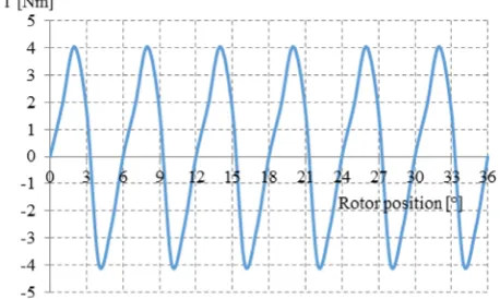
Under no load condition, the cogging torque of the proposed machine is shown in Fig. 3. The analysis was performed for one electric cycle at 25.71° of rotor position. The graph clearly shows that six cycles cogging torque with the maximum peak-to-peak of 7.99 Nm was pro-duced. The peak-to-peak cogging torque is within the acceptable range as compared to the maximum target torque. The peak-to-peak cogging torque was expected to be reduced by improving the initial design machine.
Furthermore, the induced voltages of various DC FEC current densities at a rated speed of 3000 r/min are plotted as shown in Fig. 4. The induced voltage at PM only has the lowest magnitude of ~81.58 V, whereas the highest magnitude recorded was 319.68 V at a DC FEC current density of 15 A/mm2. At no DC FEC current density, the graph is almost sinusoidal, but when the DC FEC current density is further increased, the induced voltage becomes distorted because some of the fluxes from PM are can-celled by the flux generated from DC FEC.
The flux linkages of the proposed machine at various
DC FEC current densities are shown in Fig. 5. With increasing DC FEC current density, Je, the flux linkage increased and reached to the maximum when Je was set to 10 A/mm2. The maximum flux linkage at this condition was ~0.051 Wb, which increased more than thrice when compared to the flux linkage coming from the PM only. With further increase in the Je, the flux linkage starts to decrease and finally when the Je was set to a maximum of 30 A/mm2, the magnitude of flux linkage was ~0.028 Wb. This phenomenon is expected because of the flux saturat-ion when Je >10 A/mm2 is injected to the system. Thus, this analysis has proved that the additional DC FEC can improve the flux generated from the PM to provide higher torque and offers variable flux control capability.
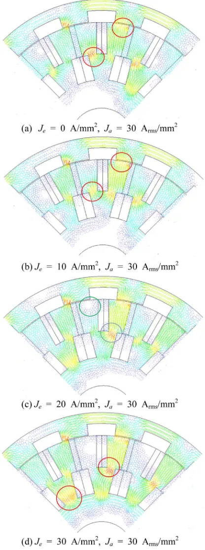
Further investigations on the flux distribution at several current densities to identify the root cause of the perfor-mance reduction were conducted, as shown in Fig. 6. The analysis was performed at a constant armature current density of 30 Arms/mm2 at the DC FEC current densities of 0, 10, 20, and 30 A/mm2. From the results, at a Je of 0 A/mm2, the flux flows easily from the stator to the rotor and returns back to the stator through the adjacent rotor pole making a complete cycle of PM flux. However, at the some portion, there is flux saturation especially on the
Wcore = Vcore × Dcore
[image:4.595.321.536.108.236.2]Wcu = (Vcoil slot– +Vcoil end– ) × Dcu
Fig. 3. (Color online) Cogging torque.
Fig. 4. (Color online) Back-emf at 3000 r/min.
Fig. 5. (Color online) Flux linkage at various DC FEC current
[image:4.595.314.544.272.409.2] [image:4.595.52.281.607.744.2]region circled by the red color in Fig. 6(a). When a low Je of 10 A/mm2 is applied to the system, more flux is gene-rated and obviously the flux saturation decreased because of the flux cancellation between the flux of PM and flux
of DC FEC as shown by the circled region in Fig. 6(b). Hence, when the Je was increased to 20 A/mm2, more fluxes flow to the rotor as well as on the inner stator back yoke, resulting flux saturation between the DC FEC and armature coil slots as indicated by the blue circle in Fig. 6(c). Moreover, some of the flux from DC FEC is can-celled with the flux from the PM at the area indicated by the green circle, and the remaining fluxes are forced to flow through the inner stator back yoke. Finally, when the
Je was set at a maximum of 30 A/mm2, the fluxes are totally saturated in the region of the adjacent DC FEC slot and between the DC FEC and armature coil slots as shown by the red circle in Fig. 6(d). Therefore, the design refinement and improvement especially on the abovemen-tioned region shall be conducted to decrease the flux saturation, hence improving the performances.
Finally, the torque productions of the original design machine at various current densities were also investi-gated. In this design, the torque versus DC FEC current density Je at various armature current densities was plott-ed, as shown in Fig. 7. Both the armature current and DC FEC current densities were varied from 0 (Arms or A)/ mm2 to 30 (Arms or A)/mm2. The graph shows that the
torque increased with increasing Je up to a certain point. Once the torque reaches its maximum point, the torque starts to decrease when higher Je was applied. This pattern is almost similar for the entire condition of armature current densities.
[image:5.595.62.270.178.735.2]This phenomenon validates the flux conditions discuss-ed above in which some of the flux has saturatdiscuss-ed at a certain condition of current density. Moreover, the reduc-tion of torque when reaching its maximum point is because of the flux cancellation between the excitation flux and armature coil flux, thus producing a much negative torque. Again, the design refinement of the distance between the DC FEC and armature coil slots and also the distance between the adjacent of the DC FEC slot should be implemented to avoid flux saturation.
Fig. 6. (Color online) Magnetic flux distribution on quarter of
[image:5.595.315.544.609.741.2]4. Design Improvement and Optimization
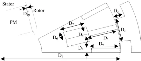
To overcome the highlighted problems of the original design machine, some design parameters were introduced in the stator and rotor parts as shown in Fig. 8. In general, the design parameters are divided into four groups, relating to the rotor core, PM, FEC slot, and armature coil slot. To find the optimal performances, each parameter was treated individually from D1 to D10 under the same
volume of PM and air gap length. The inner rotor radius, D1, is the first treated parameter, which is considered as a
dominant parameter to improve the torque. Once the optimal torque and power are achieved by treating D1, then D2 and D3 are adjusted until the combination of
maximum torque and power is obtained. Then, the same procedure is applied to the rest of the components. The second step is carried out by updating the PM slot para-meters D4 and D5, while keeping the other parameters constant. With the optimal results obtained in the second step, the FEC slot parameters of D6 and D7 are then varied
in the third step. Then, the same procedure is applied for the fourth step that relates to the armature coil slot para-meters of D8 and D9 once the optimal torque and power
are achieved in the third step. In this step, the parameters are treated by ensuring the number of turns of armature coil, considering Na to be an integer number. At last, the parameter of D10 is adjusted by keeping the same PM volume and all the parameters of D1 to D9. The design method is treated repeatedly by varying D1 to D10 until
the target maximum torque and power are achieved. Finally, to allow the magnetic flux to flow easily and smoothly between the adjacent FEC slots and between the armature and FEC slots, both the armature and FEC slots shape are changed from the rectangular to trapezoidal shape. More-over, some of the coil edges are redesigned to have a curve shape to provide optimal performances. Along the optimization process, the air gap length of the machine was kept constant at 0.8 mm. After several cycles of optimization, the outer-rotor PMFSM with 1.0 kg PM successfully achieved the target performances of maximum
torque and power.
5. Optimized Design and Results
5.1. Comparison of Original and Optimized Design Machine
A comparison of original and final designs outer-rotor PMFSM with DC FEC is shown in Fig. 9. The final design machine has a sufficient distance between the adjacent FEC slot and between the FEC and armature coil slots, allowing the magnetic flux to flow smoothly as indicated by the dotted circle in Fig. 9(b). In contrast, the flux distribution at high Je condition of 25 and 30 A/mm2 is shown in Fig. 10. Because the spaces between the ad-jacent FEC slots and between the FEC slot and armature coil were increased, the magnetic flux saturation caused by higher excitation current was mitigated. Thus, the final design machine has the ability to maintain the torque production under high excitation current conditions.
5.2. Torque Characteristics at Various Current Densi-ties
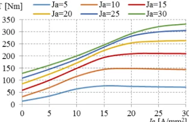
[image:6.595.320.541.107.228.2]The analysis of torque versus FEC current density at various armature current densities is shown in Fig. 11. Both the armature and FEC current densities were varied
[image:6.595.320.536.613.734.2]Fig. 8. Design parameters definition of D1 to D10.
Fig. 9. (Color online) Comparison of the original and final
designs outer-rotor PMFSM with DC FEC.
Fig. 10. (Color online) Comparison of magnetic flux
[image:6.595.48.282.643.745.2]up to the maximum of 30 Arms/mm2 and 30 A/mm2,
respectively. It is comprehensible that an increase in the armature current density will increase the torque perfor-mance, thus a maximum torque of 332.57 Nm was achieved at the maximum armature current and excitation current densities.
To investigate the optimal torque performance, the average torque values at various current phase angles at the maximum DC FEC current density were predicted as shown in Fig. 12. The maximum torque of 335.08 Nm was obtained at a current phase angle of 10° when both the armature and DC FEC current densities were set at 30 Arms/mm2 and 30 A/mm2, respectively.
5.3. Torque and Power versus Speed Characteristics
The comparison of torque versus speed characteristic of the final design outer-rotor PMFSM with DC FEC and IPMSM conventionally used in the existing HEV is shown in Fig. 13. The graph clearly shows that the final design machine produced better torque speed ranges and much higher torque capability. The maximum torque of 335.08 Nm was achieved for the final design machine at a base speed of 4,149 r/min. In contrast, a maximum torque
of 333 Nm at a base speed of 2,100 r/min was produced for IPMSM. The extra advantage of the final design machine is that the machine can operate up to a maximum speed of 20,000 r/min, whereas the maximum speed of IPMSM was only up to 12,400 r/min.
Meanwhile, the comparisons of power versus speed characteristics between the final design machine and conventional IPMSM are also analyzed in the same graph. The graph shows that initially the power curve characteristic of IPMSM increases up to the maximum point but starts to decrease with further increase in the speed. The maximum power of IPMSM was 123 kW at a speed and torque of ~4,600 r/min and 260 Nm, respec-tively, whereas for the final design machine, initially the power also increased up to a speed of 7,919 r/min and was constant in the high-speed region. The power achieved at a maximum torque of 335.08 Nm was 145.59 kW at a speed of 4,149 r/min, whereas the maximum power obtained was 160.2 kW at a speed and torque of 7,919 r/ min and 193.17 Nm, respectively. In contrast, from the torque and power versus speed characteristic, the final design machine of the outer-rotor PMFSM with DC FEC is much better than the conventional IPMSM, because of its high and constant power in the high-speed region. Finally, at the calculated weight of 27.03 kg for the final design machine, the maximum torque and power densities of 12.4 Nm/kg and 5.93 kW/kg, respectively, were achieved.
5.4. Losses and Efficiency
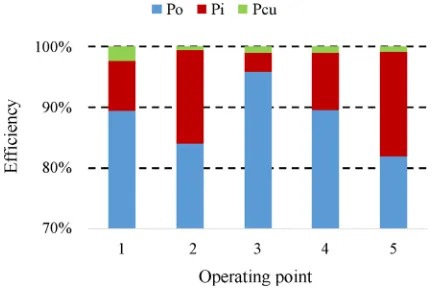
[image:7.595.326.536.102.244.2]The motor copper loss, iron loss, and efficiency were calculated considering the copper losses in armature and FEC windings and iron loss in all the laminated cores. The specific operating points at the base speed, high speed, and frequent operating conditions under a low load marked by No. 1 to No. 5 are shown in Fig. 13. More-over, the detail loss analysis and motor efficiency of the
Fig. 11. (Color online) Torque versus FEC current density at
[image:7.595.70.264.105.231.2]various armature currents.
Fig. 12. (Color online) Torque-current phase angle
character-istics.
Fig. 13. (Color online) Torque and power versus speed
[image:7.595.63.269.280.424.2]final design machine are illustrated in Fig.14. The output power, iron loss, and copper loss of the machine are indicated by Po, Pi, and Pcu, respectively. The machine has a high efficiency at the base speed and normal operation condition, labeled by Nos. 1, 3, and 4. However, at a high speed of 15,000 r/min, the efficiency of the machine slightly decreased, because of high iron loss.
6. Conclusions
A comprehensive analysis of 12S-14P outer-rotor PMFSM with DC FEC for in-wheel direct drive EV was carried out. The 2D-FEA models and the optimization of several machine’s parameters by the “deterministic optimization approach” to decompose the maximum output torque and power densities are discussed in details. The final design machine offers the advantages of robust rotor structure, lighter weight, flux control capability, and much higher torque and power densities. With only 1.0 kg of PM weight and average efficiency at a low speed operating point of 88%, the proposed machine has a great potential to be applied for in-wheel drive EV.
Acknowledgements
This study was supported by the Fundamental Research Grant Scheme (FRGS), Vote No. 1508, the Ministry of Education Malaysia and Office for Research, Innovation, Commercialization and Consultancy Management (ORICC), Universiti Tun Hussein Onn Malaysia, Johor.
References
[1] V. Bucha, Journal of Atmospheric and Terrestrial Physics 53, 1161 (1991).
[2] J. King, The King Review of low-carbon cars - Part II: Recommendations for action (March 2008). Available online: www.hm-treasury.gov.uk/king.
[3] Sung-Il Kim, Sunghyuk Park; Taesang Park, Jinwoo Cho, Wonho Kim, and Seongtaek Lim, IEEE Trans. Ind. Elec-tron. 61, 5763 (2014).
[4] C. C. Chan, IEEE Journals & Magazines 81, 1202 (1993). [5] Y. P. Yang and D. S. Chuang, IEEE Trans. Magn. 43, 51
(2007).
[6] Wu, L. Song, and S. Cui, IEEE Trans. Magn. 43, 438 (2007).
[7] K. M. Rahman, N. R. Patel, T. G. Ward, J. M. Nagashima, F. Caricchi, and F. Crescimbini, IEEE Trans. Ind. Appl. 42, 1185 (2006).
[8] Z. Q. Zhu and D. Howe, Proc. IEEE 95, 746 (2007). [9] D. Dorrell, L. Parsa, and I. Boldea, IEEE Trans. Ind.
Electron. 61, 5693 (2014).
[10] K. T. Chau, C. C. Chan, and Chunhua Liu, IEEE Trans. Ind. Electron. 55, 2246 (2008).
[11] Y. Amara, E. Hoang, M. Gabsi, and M. Lecrivain, Euro. Trans. Electron. Power 15, 497 (2005).
[12] C. Pollock, H. Pollock, R. Borron, J. R. Coles, D. Moule, A. Court, and R. Sutton, IEEE Trans. Ind. Appl. 42, 1177 (2006).
[13] M. J. Jin, Y. Wang, J. X. Shen, P. C. K. Luk, W. Z. Fei, and C. F. Wang, IET Electric Power Appl. 4, 647 (2010). [14] H. Pollock, C. Pollock, R. T. Walter, and B. V. Gorti, Proc. IEEE Ind. Appl. Soc. Annu. Meeting (2003) pp. 1451-1457.
[15] E. Sulaiman, T. Kosaka, and N Matsui, IEEE Trans. Magn. 47, 4453 (2011).
[16] J. T. Chen and Z. Q. Zhu, IEEE Trans. Energy Conver-sion 25, 293 (2010).
[17] Y. Wang and Z. Deng, IEEE Trans. Magn. 48, 2518 (2012).
[18] Y. Tang, J. J. H. Paulides, T. E. Motoasca, and E. A. Lomonova, IEEE Trans. Magn. 48, 3583 (2012). [19] E. Sulaiman, T. Kosaka, and N. Matsui, Renewable and
Sustainable Energy Reviews 34, 517 (2014).
[20] Y. Wang, M. J. Jin, J. Shen, W. Z. Fei, and P. C. K. Luk, Energy Conversion Congress and Exposition (ECCE) (2010) pp. 1723-1730.
[21] W. Fei, P. Chi K. Luk, J. X. Shen, Y. Wang, and M. Jin, IEEE Trans. Ind. Appl. 48, 1496 (2012).
[image:8.595.58.278.105.249.2][22] M. Z. Ahmad, E. Sulaiman, Z. A. Haron, and F. Khan, Applied Mechanics and Materials Journal 660, 836 (2014).
Fig. 14. (Color online) Losses and efficiency of the final