ELECTRODEPOSITION OF NICKEL/COPPER MULTI-NANOLAYER BY DUAL BATH TECHNIQUE AT AMBIENT TEMPERATURE
SHARIFAH SAKINAH BINTI ABDULLAH
A thesis submitted in partial
fulfillment of the requirement for the award of the degree of Master of Science
Faculty of Science, Technology and Human Development Universiti Tun Hussein Onn Malaysia
ELECTRODEPOSITION OF NICKEL/COPPER
MULTI-NANOLAYER BY DUAL BATH TECHNIQUE
AT AMBIENT TEMPERATURE
SHARIFAH SAKINAH BINTI ABDULLAH
ACKNOWLEDGEMENT
The success of any project relies heavily on the encouragement and guidelines of
many others. I would like to take this opportunity to express my gratitude to all those
people who made this thesis possible and gave me such an enjoyable experience.
First and foremost, I would like to express my highest appreciation and
gratitude to my supervisor Dr. Suzi Salwah Binti Jikan for her patience, advice,
encouragement, continuous guidance and supervision during this tough period to
complete the project. There are no such words in the dictionary that can express my
deepest appreciation. You are always the best. Secondly, I would like to thank my
co-supervisor, Dr. Nur Azam Bin Badarulzaman, who gave me the golden kindness,
advice, helps and support during this research. You are always the best.
In addition, warmest thanks to the metallurgy lab technician, En Abu Bakar
Bin Ahmad for providing me a good research environment and facilities to complete
this project. Also, thanks to the technician from material lab, Tuan Haji Tarmizi Bin
Haji Nasir and En Khairul Anuar Bin Ismail for guiding me in carrying out the
Scanning Electron Microscopy (SEM) and X-Ray Diffraction (XRD) analyses. Lots
of thanks to all postgraduate students, especially Siti Rodiah, Ainor Hayat, Abdullah
and Siti Salwa for their supports and kindness.
Last but not least, an honorable mention goes to my dad, Abdullah Bin
Hassan for his understanding and support. Thank you so much to my mom, Samiah
Bin Buniran for her love and trust. Not forgotten to my husband, En Arif Zakwan
Bin Ashari for his moral support and the wise advice throughout this project. I would
also like to express my gratitude for the assistance from Research Acculturation
Grant Scheme (Vot RO18, Malaysia Ministry of Education) for funding this
research. Without the help from those that I mentioned above, I would face many
difficulties while doing this project. I hope, all the knowledge and experiences
v
TABLE OF CONTENTS
DECLARATION ii
DEDICATION iii
ACKNOWLEDGEMENT iv
TABLE OF CONTENTS v
LIST OF TABLES x
LIST OF FIGURES xi
LIST OF SYMBOL AND ABBREVIATIONS xiv
LIST OF APPENDICES xvi
ABSTRACT xvii
ABSTRAK xix
CHAPTER 1 INTRODUCTION 1
1.1 Research Background 1
1.2 Problem Statement 4
1.3 Research Objectives 6
1.4 Research Scopes 6
1.5 Application of Multilayer Coatings 8
CHAPTER 2 LITERATURE REVIEW 10
2.1 Nickel (Ni) 10
2.3 Compositionally Modulated Multilayer (CMM) 14
2.4 Electrodeposition 15
2.5 Electrodeposition of Ni/Cu Multilayer Systems 18
2.6 Dual Bath Technique (DBT) 19
2.7 Direct Current (DC) Electrodeposition 21
2.8 Current Density 21
2.9 Decomposition Potential 22
2.10 Hydrogen Evolution 24
2.11 Substrate Preparation 25
2.12 The Electrochemical Reactions of Ni/Cu Multilayer
26
2.13 Experimental Parameters 28
2.13.1 Effect of Current Density 28
2.13.2 Effect of Temperature 29
2.13.3 Effect of pH 30
2.14 Mechanisms of Electrodeposition 31
2.15 Morphological Analysis 34
2.16 Phase Analysis 36
2.17 Hardness Analysis 39
2.18 Corrosion Behaviour 43
2.19 Corrosion Rate –Potentiodynamic Polarization Scans
44
2.20 Corrosion Rate- Linear Polarization Resistance Method
46
2.21 Corrosion Rate - Polarization Resistance Measurements
vii
2.22 Conversion of Icorr into the Corrosion Rate 48
2.23 Corrosion Rates Determination - Polarisation Measurements
48
2.24 Tafel Slopes Extrapolation Method 48
2.25 Potentiodynamic Polarization 49
CHAPTER 3 RESEARCH METHODOLOGY 53
3.1 Introduction 53
3.2 Substrate Preparation 55
3.3 Anode Preparation 56
3.4 Electrolyte Preparation 56
3.5 Instrument and Apparatus 57
3.6 Part I: Preliminary Experiment of
Decomposition Potential
57
3.7 Part II: Electrodeposition of Ni/Cu
Multi-Nanolayer
59
3.7.1 Production of Ni/Cu Multi-Nanolayer 60
3.7.2 Electrodeposition for Ni and Cu Electrolytes
62
3.8 Part III: Characterisation of the Sample 62
3.8.1 Sample Preparation 62
3.8.2 Morphological Studies using Scanning Electron Microscopy (SEM) and Focus Ion Beam Field Emission Scanning Electron Microscopy (FIB-FESEM) with Energy Dispersive Spectrometer (EDS)
64
3.8.3 Phase Analysis by X-Ray Diffraction (XRD)
65
3.8.5 Electrochemical Studies 69
3.8.5.1 Electrochemical Test 69
3.8.5.2 Potentiodynamic Testing 71
CHAPTER 4 RESULTS AND DISCUSSION 73
4.1 Introduction 73
4.2 Preliminary Process 73
4.2.1 Decomposition Potential 73
4.2.2 Preliminary Experiment 76
4.3 Field Emission Scanning Electron Microscopy
(FESEM)
78
4.3.1 Effect of Sublayer Thickness on the Surface Morphology
78
4.3.2 Effect of Sublayer Thickness on the Cross Section of Ni/Cu Multi-Nanolayer Coating
80
4.3.3 Effect of Different Composition Ratio 85
4.4 Energy Dispersive Spectroscopy (EDS)
Analysis
86
4.5 X-Ray Diffraction (XRD) Analysis 90
4.5.1 Effect of Sublayer Thickness 90
4.5.2 Effect of Electrolyte Temperature 93
4.6 Hardness Results Analysis 95
4.6.1 Effect of Sublayer Thickness 96
4.6.2 Effect of Ni/Cu Sublayer Ratio 97
ix
4.7 Corrosion Behaviour of Ni/Cu Multi-Nanolayer
Coating
100
4.7.1 Effect of Sublayer Thickness 100
4.7.2 Effect of Different Sublayer Ratio 103
4.7.3 Effect of Different Electrolyte Temperature
106
CHAPTER 5 CONCLUSIONS AND SUGGESTIONS FOR
FUTURE RESEARCH
109
5.1 Conclusions 109
5.2 Suggestions for Future Research 110
REFERENCES 111
APPENDICES 123
PUBLICATIONS 128
LIST OF TABLES
2.1 List of advantages and disadvantages of Ni
electrodeposition (Loweinheim, 1978)
11
2.2 List of advantages and disadvantages of Cu
electrodeposition (Loweinheim, 1978)
13
2.3 Summary of multilayer structures via dual bath
technique
20
2.4 Listof Eº values of some metal (Vany´sek, 2000) 27
3.1 The compositions of chemicals for the Watts
electrolyte
56
3.2 Apparatus used in the electrodeposition of Ni/Cu
multi-nanolayer
60
3.3 Deposition rate for Nickel (Ni) and Copper (Cu)
coating
62
4.1 EDS data for (a) 40 nm (b) 60 nm (c) 80 nm and (d)
100 nm of multi-nanolayer coating
90
4.2 XRD data for 20 nm, 40 nm, 60 nm, 80 nm, 100 nm
and Cu substrate
91
4.3 XRD data for samples prepared at different
electrolyte temperatures of 25 °C, 40 ºC and 60 °C
94
4.4 Electrochemical parameters of Ni/Cu multi-nanolayer
and Cu substrate in 3.5 wt.% NaCl
102
4.5 Electrochemical parameters of Ni/Cu multi-nanolayer
with different sublayer ratio in 3.5 wt.% NaCl
105
4.6 Electrochemical parameters of Ni/Cu multi-nanolayer
prepared at different electrolyte temperatures
xi
LIST OF FIGURES
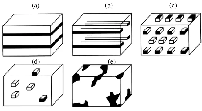
2.1 Several types of dimensional structures of
nanostructured materials (a) Quantum wells (b) quantum wires (c) ordered arrays of quantum boxes (d) Random quantum dots and (e) an aggregate of nanometer-size grains (Schlesinger & Paunovic 2000)
14
2.2 An electrolytic cell 16
2.3 Measurement of decomposition potential (a)
current –voltage diagram (b) Experimental set-up (Sivasankar, 2008)
23
2.4 SEM images of samples obtained by DC plating.
All samples having an approximate thickness of
350 nm at different current densities (Liu et al.,
2010)
29
2.5 Mechanism of particle codeposition in forming
metal deposit (Low et al, 2006)
32
2.6 Diagram of the crystallisation process: the theory
of Kossel and Stranski (Nageswar, 1975)
33
2.7 SEM and TEM showing cross-sections of the
Ni/Cu multi-nanolayers (Kaneko et al., 2005).
34
2.8 SEM of a Cu/Ni multilayer with sublayer
thickness of 100 nm
35
2.9 X-ray diffraction patterns of the multilayer coating
which consist of alternating Cu and Ni layers with sublayer thickness of 20 nm (Rajasekharan & Mohan, 2009).
39
2.10 A schematic diagram of the cross sectional of an
indentation (Oliver & Pharr, 2004)
2.11 Dependence of the Vickers hardness on individual layer thickness of the Ni/Cu multilayer, where the ratio of Ni and Cu layer thickness was 1:1
(Kaneko et al., 2005)
42
2.12 Semilogarithmic polarization curves for a
corrosion system under activation control (Tafel
behaviour) (Badae et al., 2010)
49
2.13 Comparative potentiodynamic polarization curve
of Cu–Ni alloy, Cu/Cu, and Cu substrate (Rajasekharan & Mohan, 2009)
51
3.1 Research stages for the production of Ni/Cu
multi-nanolayer coating
54
3.2 The illustration of Cu substrate used in the
electrodeposition of Ni/Cu multi-nanolayer
55
3.3 Schematic diagram of the electrodeposition
process
59
3.4 Actual experimental setup for the
electrodeposition process
60
3.5 Sample (a) before polishing and (b) after polishing 63
3.6 The schematic drawing of the specimen cross
section (a) Before milling and (b) After milling by the instrument
65
3.7 Location of sample in XRD diffractometer 66
3.8 Principle of the Vickers testing (a) Vickers
Indentation (b) Measurement of impression diagonals (Oliver & Pharr, 2004)
68
3.9 Indent images of (a) Cu substrate (b)
Multi-nanolayer sample
69
3.10 A schematic representation of corrosion test for
Ni/Cu multi-nanolayer by potentiodynamic
polarization method
70
4.1 Graph of current (A) against potential (V) of an
electrolyte for (a) Ni coating (b) Cu coating
74
4.2 Cross-sectional image of alternate layer of 10 µm
of Ni/Cu multilayer on Cu substrate
xiii
4.3 Cross-sectional images of optical microscope of
alternate layer of (a) 5 µm and (b) 1 µm of Ni/Cu
multilayer on Cu substrates
78
4.4 Surface micrographs of Cu coating and Ni/Cu
multi-nanolayer at (a) 20 nm (b) 60 nm (c) 100 nm and (d) Cu coating deposited by direct current
79
4.5 Cross-sectional images of alternate layer of (a) 20
nm (b) 40 nm (c) 60 nm (d) 80 nm and (e) 100 nm of Ni/Cu multi-nanolayer on Cu substrates
82
4.6 Cross-section of the alternate layer for different
composition ratio of (a) 2Ni: 1Cu and (b) 1Ni: 1Cu of multi-nanolayer coating
85
4.7 EDS mapping for the cross-section of 80 nm
Ni/Cu multi-nanolayer coating.
87
4.8 EDS spectrums for (a) 40 nm (b) 60 nm (c) 80 nm
and (d) 100 nm of multi-nanolayer coating
89
4.9 XRD pattern for coating with sublayer thickness of
100 nm
91
4.10 Vickers Hardness values of different sublayer
thickness of multi-nanolayer coating on Cu substrate
96
4.11 Vickers Hardness values at different sublayer ratio
of multi-nanolayer coating on Cu substrate
98
4.12 Vickers Hardness values of different electrolyte
temperatures for Ni/Cu multi-nanolayer coating
99
4.13 Potentiodynamic polarisation curves of Ni/Cu
multi-nanolayer and uncoated Cu substrate
101
4.14 Potentiodynamic polarisation curves of Ni/Cu
multi-nanolayer with the composition of 1Ni: 1Cu, 1Ni: 2Cu, 2Ni: 1Cu and Cu substrate
103
4.15 Potentiodynamic polarisation curves of Ni/Cu
multi-nanolayer at different electrolyte temperatures
LISTOFSYMBOLSANDABBREVIATIONS
A - ampere
AC - alternating current
ASTM - American Society for Testing and Materials
Cu - copper
DC - direct current
EDS - Energy Dispersive Spectrometer
FSTPi - Fakulti Sains, Teknologi dan Pembangunan Insan
FIB-FESEM - Focus Ion Beam-Field Emission Scanning Electron
Microscope
H2 - hydrogen
H2O - water
H3BO3 - boric Acid
HV - vickers hardness
L - length
Ni - nickel
NiSO4.6H2O - nickel sulfate hexahydrate
NiCl2.6H2O - nickel chloride hexahydrate
O2 - oxygen
SEM - Scanning Electron Microscopy
XRD - X-Ray Diffraction
% - percentage
a - area
d - density
˚C - degree celsius
g/l - gram/liter
xv
nm - nanometer
mN - milinewton
mm - millimeter
µm - micrometer
t - time
h - height
I - current of electrodeposition
LISTOFAPPENDICES
APPENDIX TITLE PAGE
A X-Ray Diffraction of 20 nm 123
B X-Ray Diffraction of 40 nm 124
C X-Ray Diffraction of 60 nm 125
D X-Ray Diffraction of 80 nm 126
xvii
ABSTRACT
The electrodeposition of Nickel/Copper (Ni/Cu) multi-nanolayer coating has
been carried out on Cu substrate by using dual bath technique. The electrodeposition
process was carried out at electrolyte temperatures of 25 °C, 40 °C, and 60 °C. The
Watts electrolyte and Cu (II) sulphate solutions have been chosen for this
experimental work because it produced a good surface coating. This work aims to
produce different sublayer thicknesses (20 nm, 40 nm, 60 nm, 80 nm and 100 nm)
with thickness ratio of 1:1. The work also involved a study on the effect of different
sublayer thickness, the effect of multiple nanolayers with different compositions of
layer thickness (Ni:Cu = 2:1, 1:1 and 1:2) and the effects of different electrolyte
temperatures. The production Ni/Cu multi-nanolayer samples was conducted by
using current densities of Ni and Cu at 0.0527 A⋅cm-² and 0.0505 A⋅cm-²
respectively. The (FESEM) image of Ni/Cu multi-nanolayer coating showed that the
sublayer thickness of 20 nm exhibited the smallest compact cluster of
cauliflower-like appearance. The Focus ion beam FESEM images it was proven that all
respective samples (20 nm, 40 nm, 60 nm, 80, and 100 nm) were truly exist and the
multi-nanolayer structures are formed alternately of Ni and Cu layer. The uniformity
of coating composition was studied using coating composition while phase
deposition presence was evidence by using X-ray Diffraction (XRD) respectively.
The double-like peaks of XRD data indicate the pattern of alternate multilayer which
confirmed the existence of distinctive Cu and Ni layers with each of them having
their own lattice parameter. The vickers hardness result showed that the sublayer
thickness of 20 nm has highest hardness value of 504.32 Hv. The composition of the
layer with the ratio of 2:1 for Ni/Cu coating was found to contribute the highest
hardness value which is 507.54 Hv presenting an increase of 89 %. In addition, the
microhardness of Ni/Cu multi-nanolayer reached its maximum hardness value
504.34 Hv at electrolyte temperature of 25 °C. The trends of the hardness values are
properties of corrosion current density and the corrosion potential for 20 nm showed
a shift towards the more positive regions. So, the sublayer thickness of 20 nm had
excellent effect on the corrosion resistance. Ni/Cu multi-nanolayer system with the
ratio of 1:2 presented the highest corrosion resistance among other multi-nanolayer
system. The best corrosion resistance was attributed to coating samples prepared at
electrolyte temperature of 25 ºC, based on the results obtained from morphological
analyses, hardness and corrosion. In conclusion, this study has evidenced that Ni/Cu
multi-nanolayer successfully enhanced the physical and chemical properties of the
xix
ABSTRAK
Elektrosaduran Nikel/Kuprum (Ni/Cu) berbilang-lapisan nano telah dilakukan
terhadap substrat Cu melalui teknik dua rendaman. Proses elektrosaduran dilakukan
pada suhu-suhu elektrolit 25 °C, 40 °C, dan 60 °C. Elektrolit Watts dan larutan Cu
(II) sulfat dipilih untuk ujikaji ini kerana ia mampu untuk menghasilkan permukaan
salutan yang baik. Kajian bermatlamat untuk penghasilan sublapisan berketebalan 20
nm, 40 nm, 80 nm dan 100 nm, dengan nisbah ketebalan 1:1. Kajian juga melibatkan
kesan kepelbagaian ketebalan sublapisan, kesan nano lapisan dengan komposisi
ketebalan lapisan berbeza (Ni:Cu = 2:1, 1:1 and 1:2) dan kesan kepelbagaian suhu
elektrolit juga dikaji. Kajian dilakukan pada sampel Ni/Cu berbilang-lapisan nano
dengan menggunakan ketumpatan-ketumpatan arus Ni dan Cu iaitu 0.0527 A⋅cm-²
dan 0.0505 A⋅cm-², masing -masing. Imej daripada Mikroskop Imbasan Elektron
Pancaran Medan (FESEM) memaparkan morfologi permukaan salutan Ni/Cu
berbilang-lapisan nano serta menunjukkan sublapisan berketebalan 20 nm dengan
kelompok terpadat berpenampilan ‘kubis bunga’. Alur ion terfokus FESEM yang
digunakan untuk kajian keratan rentas pelbagai ketebalan sublapisan salutan Ni/Cu
menunjukkan kesemua sampel (20 nm, 40 nm, 60 nm, 80 nm, dan 100 nm)
mempunyai struktur berbilang-lapisan nano dengan lapisan-lapisan Ni dan Cu yang
berselang-seli. Keseragaman komposisi salutan dikaji menggunakan Spektrometer
Serakan Tenaga (EDS) manakala kehadiran fasa terdeposit dikaji menggunakan
Pembelauan Sinar-X (XRD). Puncak-puncak kembaran dalam XRD menunjukkan
corak selangan berbilang-lapisan yang mengesahkan kewujudan lapisan-lapisan
tersendiri Cu dan Ni dengan parameter kekisi masing-masing. Hasil ujian kekerasan
Vickers menunjukkan sublapisan berketebalan 20 nm memiliki kekerasan tertinggi
bernilai 504.34 Hv. Komposisi salutan Ni/Cu bernisbah 2:1 pula menunjukkan
kekerasan tertinggi bernilai 507.54 Hv, iaitu 89 %. Mikro kekerasan Ni/Cu
berbilang-lapisan pula mencapai nilai maksimum iaitu 504.34 Hv pada suhu
elektrolit 25 °C. Pola nilai-nilai kekerasan adalah seiring dengan hasil kajian
rintangan kakisan ke atas sampel-sampel salutan. Ciri-ciri kakisan iaitu ketumpatan
yang lebih positif. Maka,sublapisan berketebalan 20 nm memberikan rintangan
kakisan yang terbaik. Sementara itu, sistem Ni/Cu berbilang-lapisan nano bernisbah
1:2 menunjukkan rintangan kakisan tertinggi berbanding sistem-sistem berbilang-
lapisan nano yang lain. Rintangan kakisan tertinggi didapati menerusi sampel-sampel
salutan yang terhasil pada suhu elektrolit 25 °C berdasarkan keputusan yang
diperoleh dari analisis morfologi, ujian kekerasan dan kakisan. Kesimpulannya,
kajian ini telah berjaya membuktikan Ni/Cu berbilang-lapisan nano mampu
1
CHAPTER 1
INTRODUCTION
1.1 Research Background
Nickel (Ni) is one of the metal that has been recognized as an important raw material in many industries. The major countries that have reserved Ni ores are Canada, South Africa and Finland. Most of Ni consumption in the world is for producing stainless steel. Besides that, Ni metal exhibits unique properties such as fine hardness, strength, and also good resistance to corrosion (Loweinheim, 1978). Electrodeposited elemental Ni has been the material of choice to demonstrate a variety of microdevice prototypes, including micro-gears, and microcantilevers. Whereas, Copper (Cu) is produced worldwide, mostly in United States, Chile, Canada and Zaire. Cu is easily precipitated with metals that are higher in the electromotive force (EMF) series, because it has higher electropositive. It is known as native element. Cu is used in various technology applications for example, as the undercoat for plated player and as the conductor in print circuit boards. This fact shows that Cu coating is a relatively inexpensive metal material and can be deposited on top of various substrates (Gamburg & Zangari, 2011). Ni and Cu are important materials to many industries. The annual demand is bigger compared to those of many other metals. Thus, the study of Ni/Cu multi-nanolayer should be done in order to increase awareness of Ni and Cu potentials in electroplating industries.
rate, compared to that of vacuum evaporation, cold rolling, single roll rapid quenching and sputtering (Halim et al., 2012 and Ghosh et al., 2006). This technique has successfully proven by previous researchers in producing nanometallic films in various thicknesses ranging from hundreds of nanometers to tens of micrometers. Electrodeposition is versatile technique and well suited in the production of micro and nano technology. Electrodeposition has a lot of advantages such as low production cost and requires low temperature of an electrolyte (below 80 °C). In addition, through electrodeposition, the resulting multilayer is able to prevent interdiffusion and expected to have clear-cut interfaces than those prepared via dry process. So, it is capable to produce thin films in a large area and in an extremely short period of time. Moreover, this method is competent to fabricate quality structures of multilayers that give promise to the flexibility and capability of being used for parts of any size and geometry (Abdel-Karem et al., 2011 and Alper, 2004). On top of that, the process can be performed at room temperature using different kinds of substrates and less hazardous electrolyte.
The structure of multilayer coating in nanometer range has shown promising alteration in its mechanical and chemical properties than samples coated with
multilayer coating in micrometer range (Pellicer et al., 2011). Multilayer in
nanometer range has interesting mechanical properties which involve high hardness
or flow stress when the bilayer thickness is decreased to nanoscale (Kaneko et al.,
3
The production of multilayer structure can be conducted by single bath technique and dual bath technique. However, the dual bath technique has attracted many researchers in producing various multilayers, such as Zn/Co (Kirilova et al.,
1998), and Ni/Cu (Haseeb et al., 1994 and Shu et al., 2012). According to the
position in the electrochemical series, Cu can easily be electroplated in aqueous solution, however there will be problems regarding on how to prevent the formation of deposits with Ni. Thus, it is impossible to deposit a Cu layer on Ni layer. Nonetheless, by using the dual bath technique, the electrolyte solutions do not have to be compatible, because the multilayers are obtained by repeatedly transferring the substrate from one electrolyte to another different electrolyte. There are lots of advantages of dual bath technique. It is a simple method that does not have limitations and it has a wide applicability for the production of multilayer coatings. It also offers a wider choice in the selection of multilayer components and it allows the deposition to take place on unalloyed materials due to the electrochemical limitations of these unalloyed materials (Haseeb et al., 1994).
Therefore, this research work has chosen the dual bath technique to produce multilayer coating structures in nanometer range (20 nm, 40 nm, 60 nm, 80 nm, and 100 nm). This current research focuses on the element of Cu and Ni in order to form products for nanosystem applications. For this technique, the Ni/Cu multi-nanolayer can be produced by the sequential electrodeposition, where the steps start by electrodepositing the Cu substrate with the first layer in Ni electrolyte, followed by transferring into Cu electrolyte to form second layer. The layers were formed alternately. Ni/Cu multi-nanolayer is an interesting technological system because it is electrochemically easy to grow in a well-controlled environment. The coherency to form alternate layer of Ni/Cu attributed to the fact that Cu and Ni possess the same face centered cubic (F.C.C) structures (Barshilia & Rajam, 2002), identical atomic rays, electronegativity and similar electron valences. Moreover, the isomorphic mechanism of Ni/Cu multilayer is also able to complete the solubility of the two components in liquid and solid states (Melo et al., 2011).
production of multi-nanolayer coating at ambient temperature especially in the study on the effect of different sublayer thicknesses, the effect of different ratios of the sublayer thickness and the effect of the electrolyte temperatures on the properties of this multi-nanolayer coating.
1.2 Problem Statement
The development and characterization of nanostructure materials have been subjected as intensive researches in scientific and industrial communities (Rashidi & Amadeh, 2010). Nanostructured materials with sizes of less than 100 nm are important for various industrial applications. It is expected that these nanostructured materials can enhance the physical and chemical properties of the end products (Miyake et al., 2001). Among various manufacturing methods, the electroplating has received considerable attention as this method is more practical and economical. The studies on Ni/Cu electrodeposition had been performed by other workers and they had reported the mechanism and characteristics of Ni/Cu electrodeposition (Tokarz
et al., 2007; Kim et al., 2005; Kaneko et al., 2005; Ren et al., 2004; Barshilia &
Rajam, 2002; Lassri et al., 2001; and Zhang et al., 2009).
Ambient temperature has attracted interest to this research work as the electrolyte temperature for the electrodeposition because it portrays several satisfying properties such as no hydrogen evolution, high conductivity, non flammability and
chemical stability over a wide temperature range (Koura et al., 2003). Eventhough
Beverskog & Puigdomenech, (1997) had stated that the possibilities of Ni deposited at below 30 °C, most of the research works were maintaining the usual temperature range of Watts electrolyte that is around 30 °C to 80 °C. In addition, other researchers and chemical producer companies practice the specified temperature range which is around 55 °C to 65 °C. Lower deposition temperature below the range of 55 ºC to 65 °C has to be avoided as it will not produce a bright Ni or Cu layers by normal plating time.
5
The high temperature of electrolyte produces weak coating properties. It is due to the hydrogen evolution. The increase of the deposition temperature will increase the hydrogen evolution and may lead to an increase in the porosity and crack in the coatings. Zentner et al. (1953) mentioned that according to their research findings, it could be possible to successfully deposit metals at lower temperature than the usual deposition temperature. Their findings on depositing metals at lower temperature range suggested that the deposition process at lower temperature has the potential in
obtaining harder Ni coating. Nevertheless, Badarulzaman et al. had successfully
formed the coating at a lower temperature which is at ambient temperature. However, their work is not on multi-nanolayer coatings. Due to that reason, this research work has selected the ambient temperature in performing the research work in producing thin layer as thin as nanolayer.
The microstructure and surface texture can be tailored by controlling growth parameters such as deposition or electrolyte temperature in order to obtain the good desired coating properties. The electrolyte temperature is one of the important factors to produce the coating with desired properties. However, there are insufficient electrodeposition studies that were done at ambient temperature, thus deposition temperature at ambient temperature need to be investigated. Moreover, the results of the electroplating experiments obtained from previous researchers were difficult to optimize due to inconsistent or different data. Rashidi & Amadeh (2010) found that the grain size of the deposits increases by increasing the bath temperature. The results for plating temperature only for above 55 °C is consistent with other findings. Nonetheless, for plating temperature at lower than 55 °C, it displayed unexpected behavior which is an increase in the electrolyte temperature leading to grain refining of the Ni deposits. Moreover, there is less information discussing on the effects of electrolyte temperature to the deposits. Whereas, in some studies, they are more focusing on the deviation of more than 5 °C of plating temperature from the optimum temperature (Rashidi & Amadeh, 2010).
plating process, and most Cu salts dissociate completely in water. Furthermore, the deposition current densities of Cu and Ni are some of the vital parameters in electrodeposition process. The deposition current densities obtained from the early stage of the research work will be implemented in all electrodeposition activities in this work. Thus, the obtained values of these deposition current densities lead to easier usage of different electrolytes. The experimental results are also expected to give valuable informations on the influences of electrolyte temperature, sublayer thickness and sublayer ratio. The enhancement in corrosion resistance and microhardness of Ni/Cu multi-nanolayer deposited on Cu substrate has been expected as the outcome of these research works.
1.3 Research Objectives
This research was carried out to achieve the following objectives:
1. To synthesise multi-nanolayer of Ni/Cu coated on the Cu substrate using dual bath technique (DBT). The multi-nanolayer of Ni/Cu coating produced forming different sublayer thickness with alternate layer of five different nanometer scale (20 nm, 40 nm, 60 nm, 80 nm, and 100 nm).
2. To study the effects of different sublayer thicknesses, different sublayer ratios of thickness and different electrolyte temperatures on the properties of multi-nanolayer of Ni/Cu coating.
3. To analyse the morphology, element, phase, hardness and corrosion properties of multi-nanolayer of Ni/Cu coating produced at different electrolyte temperatures with different sublayer thicknesses and different sublayer thickness ratios.
1.4 Research Scopes
7
20 nm, 40 nm, 60 nm, 80 nm and 100 nm will be studied. The effect of different sublayer ratios of Cu and Ni with the ratios of 1:1, 1:2 and 2:1 will be investigated
and finally, the effect of various electrolyte temperatures (25 °C, 40 °C and 60 °C)
will be explored.
Part I- Preliminary experiment
(a) The decomposition potential test for Ni and Cu has been carried out in order to identify the most efficient current density during the electrodeposition process. (b) The data was derived from the graph of current (ampere, A) against potential (volt, V).
Part II- Electrodeposition process to produce Ni/Cu multi-nanolayer coatings at various conditions:
(a) The Watts and Cu (II) sulfate solutions were used as the electrolytes.
(b) The different sublayer thicknesses (20 nm, 40 nm, 60 nm, 80 nm and 100 nm) were prepared.
(c) The different sublayer ratios of (Ni:Cu = 2:1, 1:1 and 1:2) were produced.
(d) The Ni/Cu multi-nanolayers of 20 nm were preparedin order to study the effects
of electrolyte temperatures (25 °C, 40 °C and 60 °C).
(e) The individual layer thickness was controlled by adjusting their deposition time.
Part III-Characterisation
(a) Scanning Electron Microscope (SEM) was used to view the surface and the cross-sectional morphologies of the Ni/Cu multilayer coating.
(b) Focus Ion Beam Field Emission Scanning Electron Microscope (FIB-FESEM) to study the Ni/Cu multi-nanolayer by to distinguish the sublayer thicknesses of alternate nanolayers of Ni/Cu on a Cu substrate.
(c) Energy Dispersive Spectrometer (EDS) for elemental study (d) X-ray Diffraction (XRD) for phase analysis.
(e) Vickers hardness for determined the hardness and strength studies
1.5 Application of Multilayer Coatings
Metallic multilayer coating has shown significant uses in various applications such as automotive, magnetic recording, media, X-ray mirrors, diffusion barrier coatings and wear resistant coatings due to its superior physical properties (magnetic, optical and
mechanical) (Ren et al., 2004). Multilayer coating with sublayer thickness in
nanometer range has got tremendous attractions from scientific and engineering communities because of its improved mechanical properties such as strength, hardness, wear resistance and corrosion resistance (Ghosh et al., 2007, Fei & Wilcox, 2006 and Zhang et al., 1998).
It also involves the applications of multilayered construction of magnetic heads, disks in magnetic rigid disk drives, various components in micro electromechanical systems (MEMS) devices and head tape devices. Moreover, the tribological properties of these layered structures are important in these applications because the ratio of the layers to the substrate depend largely on the layer properties such as the layer thickness, surface roughness and elastic modulus. Due to these reasons, most of the researches conducted were to synthesis the layers for the applications of these devices are as thin as 1 nm (Ghosh et al., 2007). In addition, the multilayered structures are also used in variety of applications such as X-ray mirrors and diffusion barrier coating due to its superior physical properties (Ren et al., 2004). The multilayer’s films are usually fabricated by dry processes such as sputtering, vacuum evaporation and molecular beam epitaxy (MBE) which are proven to be the most suitable techniques in order to produce high quality structures with atomic scale. However, the electrochemical deposition exhibits more interesting technique since the electrodeposition process can be altered to reduce the production time. Thus, this activity applies an economically technique (Miyake et al., 2001).
The electrodeposition of Ni/Cu has a broad use in various seawater applications such as valves, condensers and heat exchanger tubes. It is highly corrosion resistant in seawater, acidic or alkaline media and in many oxidizing or
reducing gas environments (Kaneko et al., 2005). Nowadays, the study on Ni/Cu
9
safer and less raw material needed. Due to that reason, this study focuses on the nanolayer of Ni/Cu as a hope that the findings would be useful for nanotechnology applications.
CHAPTER 2
LITERATURE REVIEW
2.1 Nickel (Ni)
Nickel (Ni) is the twenty-fourth most abundant element in the lithosphere (Lowenheim, 1978). It offers unique properties such as fine hardness, strength, and good ductility, and toughness, lustrous and good conducting electricity. Due to its unique properties, up to 70 % of Ni is widely used in the stainless steel production. In the earth crust, Ni exists about 0.01 % mainly as sulphide, oxide and silicate mineral. In natural geological activities, Ni is produced by weathering and volcanoes which lead to major Ni distribution in the natural environment (Schaumloffel, 2012). Ni has an atomic number of 28.
The retrospective on Ni started with Ni electrodeposition using ammonium sulfate solution that was developed by Dr. Isaac Adams, who was one of the first to commercialise Ni plating in the United States in 1869. In 1916, Professor Oliver Watts at the University of Wisconsin formulated Watts solution. Watts electrolytes are the combinations of nickel sulfate, nickel chloride and boric acid (Schlesinger & Paunovic, 2000).
Ni coatings are commonly used due to their high corrosion resistance and attractive visual appearance. The electrodeposition process of Ni is similar to other electrodeposition processes which involves soluble metal anode. It also requires conductive aqueous solution of Ni salts to channel the direct current between two electrodes. There are few types of solutions that are used for Ni electroplating;
• Watts Ni plating solution
• Ni sulfamate solution
11
• Sulfate-Chloride solution
• All-Sulfate solution
• Hard Ni solutions
Ni sulfate is a type of electrolyte that produces lots of Ni. It is a non volatile and the cheapest among the Ni salts. While, Ni chloride is a source of chloride ions that is required to prevent the passivity of the anode and to increase the conductivity of the electrolyte. The presence of chloride ion is due to addition of Ni chloride to the electrolyte. However, there are also other chemicals such as boric acid is being added in Watts solution to serve as a weak buffer and control the pH of the cathode. It is relatively very pure, inexpensive, stable and nonvolatile (Loweinheim, 1978 and Torabinejad et al., 2017).
[image:30.612.133.523.465.716.2]The electrodeposition of Ni has been carried out using sulfate solutions which contain some chloride and boric acids. Sulfate and chloride solutions are the best of choices for the electrodeposition process due to the economic aspects. Based on previous researchers, the electrodeposition of Ni has general advantages and disadvantages that are summarised in Table 2.1.
Table 2.1: List of advantages and disadvantages of Ni electrodeposition (Loweinheim, 1978)
Advantages Disadvantages
Relatively good wear resistance The mechanical properties of the
substrate can get worse if Ni was
deposited on steel because of
hydrogenation.
Relatively high hardness Ni coating is not tolerant to mechanical
work, such as elongation, bending or riveting
Good ductility, especially when
deposited from sulfamate solutions
Ni becomes not stable in sulfur-containing media, in ammonia, in a humid chlorine atmosphere.
Ni has good anti-diffusion barrier and widely used as the barrier layer to prevent the diffusion of the substrate material to the deposit
The properties of Ni that are able to enhance surface conductance make it a relatively good electrical conductor
Ni is a magnetic metal; therefore it cannot be used when non-magnetic materials are necessary.
High corrosion resistance in conventional media, in high humidity environments or in alkali solutions or organic acids
Ni deposits may often peel away from the basis metal. Moreover, the adhesion of a subsequent deposit on top of a Ni surface is also problematic
Ni are easily deposited/soldered by using conventional method
Ni deposition is highly sensitive to impurities in the electrolyte.
Nickel and its alloys have received considerable attention among the industrialists and academicians as the most commonly used materials for anti-corrosion coatings (Qibo & Yinxin, 2013 and Jinlong et al., 2016). The study on Ni electroplating was also done for the solar applications (Nandy et al., 2016). Electrodeposition of Ni is one of the most commercial techniques that have been recognized previously as surface modification and surface finishing process. Owing to these potentials, Ni is the appropriate choice of element to be used in electrolysis reaction due to its chemical stability. The electroplating process is an effective method for obtaining Ni thin films having micro or nanostructures with good film quality and aspect ratio
(Hili et al., 2015). Ni electrodeposition falls into three functional categories which
are: decorative, functional and electroforming (DiBari, 2010 and Ebrahimi, 2001). Therefore, the electroplating method is mostly preferred if compared to other Ni
deposition techniques.
2.2 Copper (Cu)
Copper (Cu) has an atomic number of 29 and it is one of the elements in the periodic table. Cu exists in the earth’s crust about 0.001 to 0.01 ppm mainly as sulphide,
oxide and carbonates ore. The loss of d electron from multiple valences formed
coloured ions, spontaneous complex formation and typical characteristics (Lowenheim, 1978).
13
electrochemical series, Cu can easily be electroplated in aqueous solution but there will be a problem regarding on how to prevent the formation of deposits with less noble metal. The immersion deposits are usually non adherent and powdery. Most of researchers proposed the use of complexing agent to reduce the activity of Cu ions. Table 2.2 presents the list of advantages and disadvantages of Cu electrodeposition.
Table 2.2: List of advantages and disadvantages of Cu electrodeposition (Loweinheim, 1978)
Advantages Disadvantages
Highest electrical and thermal
conductivity
Under atmospheric condition, Cu deposit has a very low chemical resistance. The deposit cannot provide electrochemical protection to the substrate
Environmentally non hazardous At higher temperature Cu coatings must
have barrier layer to prevent diffusion into other metal
Cu metal indispensable component of
multilayer deposits The deposits form alloy with solders resulting in formation of intermetallic
compounds
Cu deposits usually have low internal stresses; very thick layers of coating that easily produced
Cu is unstable when in contact with many organic substances.
It is suitable for various mechanical working processes. Cu is ductile and can be easily polished
Cu is not suitable for hermetic connections, for example welded joints.
2.3 Compositionally Modulated Multilayer (CMM)
Multilayer thin film coating has received attention among researchers over the few decades for its excellent mechanical properties. Multilayer coating consists of repeating different bilayer materials of different thickness.
multilayer, accurate control of microstructure on the nanometric scale makes it possible to control not only its magnetic properties but also
(Chui & Chen, 2008 and Vella produced by the electrodeposition
such as the electrolyte concentration, the electrolyte pH, the deposition potentials, additives, substrates and the control methods (galvanostatic and potentiostatic) (Singh et al., 2009).
In nanostructural materials, the microstructural length or grain size is about 100 nm (Tjong & Chen
one-dimensional structures (more commonly known as multilayers) which are made of alternate thin layers of different composition, two
type elements suspended within a three
[image:33.612.165.491.469.649.2]constructs, which may be made of a distribution of fine particles suspended within a matrix as described in Figure 2.1
Figure 2.1: Several types of dimensional structures of nanostructured materials (a) Quantum wells (
(d) Random quantum dots and ( (a)
(d)
(c) (b)
(b)
Compositionally Modulated Multilayer (CMM)
Multilayer thin film coating has received attention among researchers over the few decades for its excellent mechanical properties. Multilayer coating consists of repeating different bilayer materials of different thickness. In electrodeposition of yer, accurate control of microstructure on the nanometric scale makes it possible to control not only its magnetic properties but also its mechanical properties
ui & Chen, 2008 and Vella et al., 2004). The properties of multilayer
by the electrodeposition process are significantly affected by parameters such as the electrolyte concentration, the electrolyte pH, the deposition potentials, additives, substrates and the control methods (galvanostatic and potentiostatic)
nanostructural materials, the microstructural length or grain size is about & Chen, 2004). They are divided into three main types which are dimensional structures (more commonly known as multilayers) which are made thin layers of different composition, two-dimensional structures (wire type elements suspended within a three-dimensional matrix), and three
constructs, which may be made of a distribution of fine particles suspended within a ed in Figure 2.1 (Schlesinger & Paunovic, 2000).
: Several types of dimensional structures of nanostructured materials wells (b) quantum wires (c) ordered arrays of quantum boxes
quantum dots and (e) an aggregate of nanometer-size grains (Schlesinger & Paunovic, 2000).
(e)
Multilayer thin film coating has received attention among researchers over the few decades for its excellent mechanical properties. Multilayer coating consists of In electrodeposition of yer, accurate control of microstructure on the nanometric scale makes it its mechanical properties The properties of multilayer structures are significantly affected by parameters such as the electrolyte concentration, the electrolyte pH, the deposition potentials, additives, substrates and the control methods (galvanostatic and potentiostatic)
nanostructural materials, the microstructural length or grain size is about are divided into three main types which are dimensional structures (more commonly known as multilayers) which are made dimensional structures (wire-dimensional matrix), and three-(wire-dimensional constructs, which may be made of a distribution of fine particles suspended within a
: Several types of dimensional structures of nanostructured materials ) ordered arrays of quantum boxes
15
Alternate layer of two different materials with different laminate thickness in the range of nanometer can be fabricated by electrochemical deposition. The electrodeposition is an inexpensive process for the production of advanced material. The multilayer can be produced in either dry or wet process. The dry process involves vacuum deposition such as evaporation, molecular beam epitaxy and sputtering. The wet process, especially electrodeposition of multilayer can be divided into two categories which are single bath technique and dual bath technique (Esmaili et al., 2011).
The multilayer involves combination of several metal of interest to form alternate layers. Go’mez et al, (2002) investigated on the electrodeposition of Co/Cu multilayer from a single electrolyte containing the Co (II) and Cu (II) ions. Wen et al. (2002) also investigated the microstructure and mechanical properties of the multilayer structure of Ni/Ru which found that the multilayer formed coherent epitaxial on each other. The considerable interests in the production of nano-dimensional multilayer structured films show large potentials applications in various technologies based on different unique properties. Therefore, in this research dual bath technique has been selected in order to produce the multi-nanolayer structure of Cu and Ni.
2.4 Electrodeposition
Electrodeposition (also termed as ‘electroplating’ or ‘electrochemical deposition’) process is a study in the fields of electrochemistry, electrochemical engineering, solid state physics, metallurgy, material and electrical (Paunovic & Schlesinger, 2006 and Loweinheim, 1978). Electrodeposition refers to the formation of metallic coating on a base material occurring through the electrochemical reduction of metal ions from
an electrolyte. Electrodeposition is simple and not expensive (Singh et al., 2009).
This process involves an electrolyte as ionic conductors to produce chemical species of metal of interest (Gamburg & Zangari, 2011). This electrochemical deposition technique is able to produce adhesive and compact coatings of metal, alloys and
composites (Safiee et al., 2016). Metal electrodeposition is one of the most
metallic structures and engineering. Moreover, it is also used in jewelry, decoration, galvanization and cast replicates for electroerosion, plastic metallization and electronic industries. Recently, this electrodeposition has been found to be the most important method especially in producing coating for environmentally energy harvesting such as solar cells and thermo electric generators (Matsuoka et al., 2015).
In general, electrodeposition process consists of dissolution of metal from an electrode (anode), into a solution containing ions of the same metal (cathode) which is in contact with the solution. The potential is applied between electrodes. Oxidation-reduction processes are produced at the electrodes. The oxidation occurs at the anode while the reduction takes place at the cathode. These reactions lead to a change in the metal oxidation state (Postigo, 2010).The electrodeposition comprises several important components which are anode, cathode, power supply and electrolyte as displayed in Figure 2.2.
Figure 2.2: An electrolytic cell
The electrodeposition involves the process of metal deposit on a particular substrate
when a current is passed through an electrolytic bath (Beltowska-Lehman et al.,
2015). Figure 2.2 is the electrolytic cell that composed of several parts. Generally, the anode is the metal that is placed at the positive terminal electrode where oxidations occur. The cathode workplace/ substrate is placed at the negative terminal of the AC or DC power supply. A voltage applied across the two electrodes will result in a potential difference. Then, the cations in the electrolyte move to the
Anode
17
cathode due to the electric field and causing the dissociated metal ions to gain electrons. At this stage, they oxidize on the surface of the cathode and form a deposited layer on the cathode metallic coating (Paunovic & Schlesinger, 2006 and Loweinhem, 1978). The movement of the cations and the electrons forms an electric current. This chemical deposition is a repeating process where the electrons flow out from the anode into the electrolyte back to the anode with the aid of the external circuit. Finally, they flow back to the cathode (Ping et al., 2011).
The Faraday’s Law is shown in equation (2.1) which relates the amount of electrical charges passed through the circuit during electrodeposition. It is used to calculate the duration of electrolysis in order to achieve a predetermined thickness.
(2.1) Where,
m is the deposited metal mass (grams)
Q is the net charge passed through the circuit (coulombs)
A is the atomic weight of the metal
n is the number of electrons per molecule of the species being reacted
F is the value gained by multiplying the electronic charge by the
Avogadro number means that 1 F equals to 96,485 C/ (mol of electrons)
At constant current
ܳ = ܫݐ (2.2)
The charge Q can be defined in terms of electric current as in Eq. (2.3).
ܳ = ݀ܫݐ (2.3) Where,
I is the total current in amperes (A)
t is the duration of the electrochemical process in seconds (s)
Other researchers are assuming 100 % efficiencies of current densities in
electrodeposition process (Alper et al., 2004 and Tsuru et al., 2002). In this study,
the electrodeposition term is defined as a process in which the deposit of a thin layer (of metal) is formed ‘electrolytically’ on a metal substrate (Sahoo, 2008). Electrodeposition has a lot of advantages such as low production cost and requires low temperature of an electrolyte. The structures and compositions of the deposits are affected by electrolyte composition, agitation of the solution, current and potential during the process.
2.5 Electrodeposition of Ni/Cu Multilayer Systems
The increasing attention in order to enhance the performance of devices and coatings has prompted research into strategies that can be implemented to decrease the dimensions of thin films and coatings without compromising their mechanical performance. Electrodeposition is one of the best methods to prepare alternate layer of element in the range of hundreds of nanometers to tens of micrometers. For an example, a successful work has resulted in enhancing performances of the samples, such as improving corrosion resistance, tribological performance, thermal stability
and having high strength and giant magneto resistance (Kurmanaeva et al., 2016).
This current research focuses on the elements such as Cu and Ni in order to form products for nanosystem applications.
The development of Ni/Cu multi-nanolayer has interest most researchers because this technological system can be electrochemically easy to grow in a well-controlled environment. The coherency to form alternate layer of Ni/Cu attributed to the fact that Cu and Ni possess the same F.C.C structures (Barshilia & Rajam, 2002), identical atomic rays, electronegativity and similar electron valences. Moreover, the isomorphic mechanism of Ni/Cu multilayer is also able to complete the solubility of
the two components in liquid and solid states (Melo et al., 2011). Nickel is an
19
According to Tench & White (1984) on the investigation of composite structures “periods” down to 100 °A, the presence of harder Ni layer in a softer Cu matrix for compositionally modulated multilayer exhibited the enhancement of their tensile strength. Yahalom & Zadok (1987) also developed a method to produce composition modulated alloys by electrodeposition of Cu and Ni which had unique properties similar to those produced via vapour deposition.
Tóth-Kádár et al. (2000) on his recent work also studied the characteristics of eletrodeposited Ni/Cu alloys and Ni-Cu/Cu multilayers. The findings proposed the growth of the multilayers via two pulse plating technique in the formation of chemically intermixed interface. They established the current density of the deposition from the measurement of the direct current. Moreover, the properties of the multilayer structure are critically dependent on the growth conditions of the Ni/Cu systems. The very perfect thin Ni–Cu/Cu multilayers can be prepared with coherent interfaces. Nonetheless, if the layer modulation wavelength is in the 10 nm range and at modulation thicknesses above 60 nm, the interfaces lose their nearly perfect coherency (Czira´ki et al., 1998).
In this present work, the research focuses on the production of alternate layer of Cu and Ni layer at ambient temperature (room temperature). The ambient temperature has been selected for the electrodeposition temperature in this work with the resistance changes of up to 55 % and the sensitivities of up to 0.07 % as successful work of using this temperature in producing Co–Cu/Cu and Co–Ni/Cu
multilayer has been reported by Czira´ki et al. (1998). Alternating layers of metal
and electrodepositing the layers at various temperatures are the parameters that need to be taken into consideration in order to get a better quality deposit. In electrodeposition, there are two major techniques for the preparation of multilayer structures by using either single-bath technique or dual bath technique.
2.6 Dual Bath Technique (DBT)
the dual-bath technique, which is conceptually simple and it involves the deposition
of the constituents by alternate immersion (Matsuoka et al., 2015). Dual Bath
Technique (DBT) has attracted many researchers to deposit various multilayers, such as Zn/Co (Kirilova et al., 1998), Ni/Cu (Haseeb et al., 1994 and Shu et al., 2012) and
Cu/Ni (Ren et al., 2011). Historically, in 1921, Blum was the first person who
employed the Dual Bath Technique (DBT) for the deposition of Ni/Cu multilayer structure. Blum’s deposit was a minimum of 5 µm sublayer thickness (Haseeb et al., 1994).
Although the single bath technique has attracted most researchers, the obvious disadvantage of the single bath technique is that more noble metal (nonmagnetic) is co-deposited during the deposition of the less noble metal component (magnetic). Thus, it is impossible to deposit a Cu layer in a Ni layer. Nonetheless, by using the dual bath technique, the more and less noble metal in the electrolyte solutions do not have to be compatible, because the multilayers are obtained by repeatedly transferring the substrate from one electrolyte to another different electrolyte. Therefore, most recent works have chosen the dual bath technique to produce multilayer structures. For this technique, each layer is deposited alternately on a particular substrate.
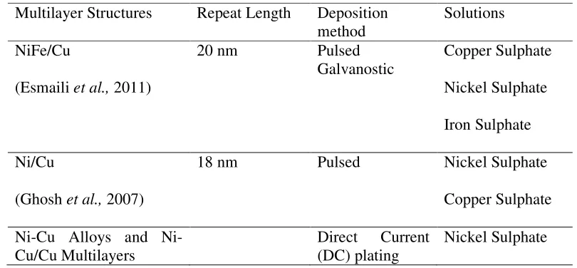
[image:39.612.122.527.538.726.2]The condition of deposition such as current density, potential, or both parameters must be different enough to allow separate electrodeposition of each layer (Haseeb et al., 1994). Table 2.3 summarizes the findings and studies of multilayer structures via dual bath technique.
Table 2.3: Summary of multilayer structures via dual bath technique
Multilayer Structures Repeat Length Deposition
method
Solutions
NiFe/Cu
(Esmaili et al., 2011)
20 nm Pulsed
Galvanostic Copper Sulphate
Nickel Sulphate
Iron Sulphate
Ni/Cu
(Ghosh et al., 2007)
18 nm Pulsed Nickel Sulphate
Copper Sulphate
Cu Alloys and Ni-Cu/Cu Multilayers
Direct Current
(DC) plating
21
(Tóth-Kádár et al., 2000) Two-pulse
plating
Galvanostatic
Copper Sulphate
Cu/Ni
(Haseeb et al., 1994)
5-100 nm Potentiostat
Galvanostatic
Copper Sulphate
Nickel Sulphate
Zn/Co
(Kirilova et al., 1998)
0.3 and 3.0 µm Galvanostatic Zinc
Cobalt
2.7 Direct Current (DC)Electrodeposition
The properties of the electrodeposited films are significantly affected by the deposition potential or current density, type of electrolyte and electrolyte temperature (Sarac & Baykul, 2013). In the conventional DC electrodeposition process, the electrical current is continuously exerted to the system in uninterruptible manner. The duty cycle is the ratio of current on time to the total time which is 100 %. Therefore the average current equals to the peak current density. This method is anold method and conventional that is used for the electrodeposition of metal and alloys. The advantage of direct current electroplating is that DC unit is cheaper than pulse generator. Moreover, this technique applies simple, economically affordable
process and easy procedures in order to attain better results (Torabinejad et al.,
2017).
2.8 Current Density
Current density is one of the most important variable since it influences the deposition rate, microstructure, chemical composition, and cost as well as strongly affecting the properties of the coating. The current density is usually assumed to be
uniformed across the surface of the coating (Paunovic & Schlesinger, 2006). Current density governs the rate of the deposition process that is usually
per square meter A⋅m-². Thus, the current density is the most suitable measure for the
rate of any electrochemical process. The equation 2.4 as follow:
Current Density, (CD)
(2.4) Where,
I is the current (A) A is the area (m²)
2.9 Decomposition Potential
The decomposition potential was discovered by Maxx Le Blanc (1865-1943). He discovered more about the phenomenon of polarization and the formation of gas films on the electrodes. Not only that, the applied EMF caused dissolution from one
electrode and deposition of metal on the other. When H2SO4 solution was
electrolysed by platinum electrodes, applying an external potential of 1.00 V, the
current flowed but suddenly stopped due to the polarization. The H2 and O2 formed a
layer at the surface of the electrodes. During the applied potential of the current, the
current suddenly increased which is caused by the evolution of H2 and O2 at the
electrodes (H2 at cathode and O2 at anode).
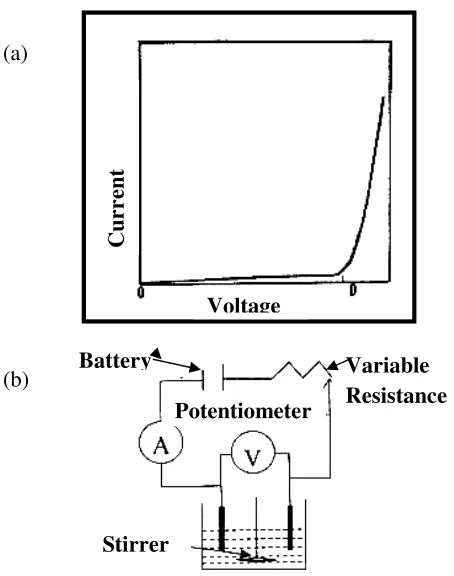
Moreover, the term decomposition potential can be defined as the maximum potential that must be applied between two electrodes of an electrolytic cell to ensure the continuous electrolysis process. It is also known as deposition or discharge potential of the sums of potential of each electrode during the electrolysis that must be greater than the reversible electrode potential. The value of decomposition potential can be determined from a plot of current versus voltage as shown in Figure 2.3 (a). As the applied voltage increased, the flow of the current and the potential difference across the electrodes were measured. The experimental setup is shown in Figure 2.3 (b). The graph explains that the initial current flow is small until it reaches the decomposition voltage. The voltage region shows the almost complete
23
[image:42.612.203.430.131.419.2]polarization for one or both electrodes. Beyond D the current increased rapidly (sudden jump) with further increase in applied e.m.f.
Figure 2.3: Measurement of decomposition potential (a) current –voltage diagram (b) Experimental set-up (Sivasankar, 2008)
Decomposition potential was involved in the preliminary work in order to
obtain the best current density for the experimental works. Qian et al. (2011)
determined the form of deposition rate for both electrolytes. The voltage values were connected with the critical deposition overpotential of each metallic ion. It was a concept where Ni was not deposited when the applied voltage was lower than 2.00 V whereas Cu was not deposited from the electrolyte until the voltage was higher than 1.00 V. The high concentration of metallic ion in the electrolyte contributed by the ion supplied to the cathode.
Badarulzaman et al. (2010) also discovered the decomposition potential of
Ni. Based on the observation, it revealed that the decomposition potential was 2.00 V with 0.12 A. Moreover, Bonhote and Landolt, (1997) revealed that Cu reduction occurred in the plateau between -0.20 V and -0.70 V of the limiting current. The sudden increase in the current at the end of the plateau was due to the Ni deposition
Voltage
C
u
rr
en
t
Variable Resistance Potentiometer
Stirrer Battery
Voltage
(a)
that started at -0.70 V. Modulating current density between high values corresponded to the simultaneous deposition of Ni and Cu.
However, Lazzari and Pace, (1975) investigated the electrochemical
properties of diethyl-triethylenediamine cuprous bromide (dtdBr2-CuBr). The
decomposition potential of the electrolyte appeared to be 0.70 V at 25 °C. Abrantes
et al. (1986) also studied the variation of decomposition potential that involved in
different electrolyte temperatures. This research revealed that below 65 ºC the decomposition potential involved was influenced by the voltage stability window. Meanwhile, at a high temperature, the reduction process was caused by a change of anodic limit.
The decomposition potential or decomposition voltage is important as the predetermining step in this work. The increase of the voltage above the decomposition voltage will increase the rate of the reaction. It was also as an approximate characteristic of the industrial electrode during the electrodeposition process.
2.10 Hydrogen Evolution
During electrodeposition process, hydrogen is the second element that is electrochemically produced at the cathode. Hydrogen evolution affects the physical
properties such as embrittlement (Gabe, 1997). The mechanism of hydrogen
evolution:
In acid solution
H+ + e- + M → M – H + H
2O (2.5)
In alkali solution
H2O + e- → Hads + OH- (2.6)
In the deposition of certain metals, hydride formations are formed by
adsorbing hydrogen (Hads). Increasing the solution temperature and current density
111
REFERENCES
Abdel-Karim, R., Reda, Y., Muhammed, M., El-Raghy, S., Shoeib, M & Ahmed, H. (2011). Electrodeposition and Characterization of Nanocrystalline Ni-Fe Alloys. Journal of Nanomaterials, pp.1 - 8. doi:10.1155/2011/519274
Abrantes, M. A., Alcacer, L. J & Sequeira, C. A. C. (1986). Thin Film Solid State Polymer Electrolytes Containing Silver, Copper and Zinc Ions as Charge Carriers. Solid State Ionics,18(19), pp. 315 - 320.
Allahyarzadeh, M. H ., Aliofkhazraei, M., Sabour, R., Rouhaghdam, R & Torabinejad, V. (2016). Gradient electrodeposition of Ni-Cu-W (alumina) nanocomposite coating. Materials and Design, 107, pp. 74–81.
Alper, M., Baykul, M. C., Pe´Ter, L & Bakony, I. (2004). Preparation and Characterisation of Electrodeposited Ni–Cu/Cu Multilayers. Journal of
Applied Electrochemistry, 34, pp. 841 – 848.
Badarulzaman, B. A., Mohamad, A. A., Puwadaria, S., & Ahmad, Z. A. (2010). The Evaluation of Nickel Deposit Obtained via Watts Electrolyte at Ambient Temperature. Journal of Coating Technology, 7 (6), pp. 815 – 820. Badea, G. E., Caraban, A., Sebesan, M., Dzitac, S., Cret, P., & Setel, A. (2010).
Polarisation Measurements Used for Corrosion Rates Determination. Journal
of Sustainable Energy, 1(1), pp.1 - 4.
Barshilia, H. C & Rajam, K. S. (2002). Characterization of Cu/Ni Multilayer Coatings by Nanoindentation and Atomic Force Microscopy. Surface and
Coatings Technology, 155, pp. 195 – 202.
Baskaran, I., Narayanan, T. S., & Stephen, A. (2006). Pulsed Electrodeposition of Nanocrystalline Cu–Ni Alloy Films and Evaluation of Their Characteristic Properties. Materials Letters,60, pp. 1990 - 1995.
Beltowska-Lehman, E., Indyka, P., Bigos, A., Szczerba, M. J., & Kot, M. (2015). Ni–W/ZrO2 Nanocomposites Obtained by Ultrasonic DC Electrodeposition.