A Study of Structural Representation of Mechanisms
Kinematic Chains
Ali Hasan
Mechanical Engineering Department, F/O-Engineering & Technology, Jamia MilliaIslamia, New Delhi *Corresponding Author: [email protected]
Copyright © 2013 Horizon Research Publishing All rights reserved.
Abstract
Kinematic chain is a combination of links connected by different kinematic pairs (joints). The study of the nature of connection among various links of a kinematic chain is known as structural analysis or topological analysis. In this paper to help the analysis, several methods of representation of the kinematic structure are presented. The study includes the functional schematic representation, structural representation, graph representation, and various matrix representations. The study is extremely useful for designer at the conceptual stage of design and research scholars in the initial stage of their research work.Keywords
Link, Kinematic Chain, Kinematic Pair, Graph And Functional Schematic Representation1. Introduction
The kinematic structure of a mechanism have the required information about which link is connected to which other link by what type of kinematic pair. The kinematic structure of a mechanism may be represented in several different ways. Some methods of representation are fairly straight forward; whereas others may be rather abstract and do not necessarily have a one-to-one correspondence. In this paper various methods of representation of the kinematic structure of a mechanism or kinematic chain are presented with the help of following some assumptions.
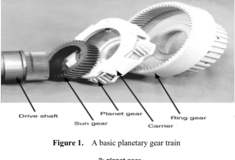
(i)All parallel redundant paths in a mechanism are shown by a single path. Parallel lines are used for increasing load capacity and achieving better dynamic balance of a mechanism. For example, Figure 1 shows the components of a basic planetary gear train whose schematic diagram is shown in Figure 2(a). Although the gear train has four planets, the structural representation is sketched with only one, as shown in Figure 2(b). Similarly, when a link is supported by several coaxial bearings, only one will be shown.
(ii) All joints are binary. A multiple joint will be substituted by a set of equivalent binary joints. In this regard, a ternary joint will be replaced by two coaxial binary joints; a quaternary joint will be replaced by three coaxial binary joints, and so on.
(iii) Two mechanical components rigidly connected for the
[image:1.595.316.550.313.472.2]ease of manufacturing or assembling will be considered and shown as one link. For example, two gears keyed together on a common shaft to form a compound gear set will be treated as one link.
Figure 1. A basic planetary gear train
Figure 2. Schematic diagram and kinematic representation
2. Functional Representation of
Mechanisms
2.1. Functional Schematic Representation
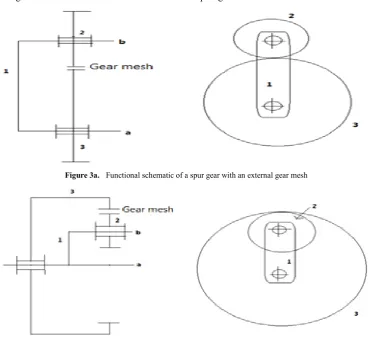
external gear mesh may share identical structural topology. Figure 3(a) is the functional schematic of a spur gear set with an external gear mesh, whereas Figure 3(b) is the functional schematic of another spur gear set with an internal gear mesh. Each of these two gear sets has three links. Gear 2 meshes
with gear 3, and link 1 is the carrier. Together, they form a one-dof gear train. In the side view of a gear pair, we use two short parallel lines to indicate the gear mesh. These two gear sets are different in design. However, their structural topologies are identical.
[image:2.595.118.487.132.476.2]Figure 3a. Functional schematic of a spur gear with an external gear mesh
Figure 3b. Functional schematic of a spur gear set with an internal gear mesh Figure 3. Functional schematics of two gear sets that share the same structural topology
Figure 4. Strctural and graph representation of links
2.2. Structural Representation
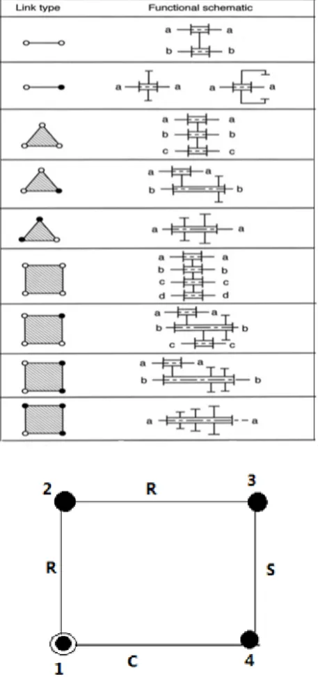
Figure 5 shows the structural representation of a RRSC spatial mechanism, where the edge label denotes the link number and the vertex label denotes the joint type. Figure 5 shows that the four links are connected in a closed loop by revolute, revolute, spherical, and calendric joints. Figure 6shows the side view of the planetary gear train in Figure 2 and the corresponding structural representation. The kinematic structure in Figure 6 may be sketched in more than one functional schematic. Gear pair can assume either external or internal gear mesh. Hence, there is no one-to-one correspondence between the functional schematic and the structural representation. We may use the symbol Gi to represent an internal gear mesh and Go an external gear mesh.
Figure 5. Structural representation of the a RRSC mechanism
Figure 6. Functional and structural representations for the planetary gear set shown in Figure 2
Table 1 shows the schematics and structural representations of some link assortments frequently used in geared kinematic chains.
2.3. Graph Representation
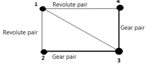
In a graph representation, the vertices denote links and the edges denote joints of a mechanism. The edge connection between vertices corresponds to the pair connection between links. To distinguish the differences between various pair connections, the edges can be labeled or colored. In the graph of a mechanism; the vertex denoting the fixed link is labeled
accordingly, usually with two small concentric circles. For example, Figure 7 shows a graph representation of the RRSC mechanism shown in Figure 5. The vertices Figure 7 are numbered from 1to 4 representing links 1 to 4, respectively, and the edges are labeled as R, R, S, and C according to the pair connections between links.
Table 1. Links assortment used in geared kinematic chains
Figure 7. Graph representation of the RRSC mechanism shown in Figure 5
or two internal meshes. The drawing of a graph from a mechanism is very simple but the inverse process, that is, the sketching of a mechanism from the graph, needs some practice to achieve better proportions.
Figure 8. Graph representation of the planetary gear set shown in Figure 2
2.3.1. Advantages of Using Graph Representation The advantages of using the graph representation are: (a) Many network properties of graphs are directly applicable. For example, we can apply Euler’s equation to obtain the loop mobility criterion of mechanisms directly. (b) The structural topology of a mechanism can be uniquely identified. Using graph representation, the similarity and difference between two different mechanism embodiments can be easily recognized.
(c)Graphs may be used as an aid for the development of computer-aided kinematic and dynamic analysis of mechanisms. For example, Freudenstein and Yang [6] applied the theory of fundamental circuits for the kinematic and static force analysis of planar spur gear trains. The theory was subsequently extended to the kinematic analysis of bevel-gear robotic mechanisms [8]. Recently a systematic methodology for the dynamic analysis of gear coupled robotic mechanisms was developed [9].
(d) Graph theory may be employed for systematic enumeration of mechanisms. [1, 2, 4, 5, 7, 10, 11-17]. (e) Graphs can be used for systematic classification of mechanisms.
(f) Graphs can be used as an aid in automated sketching of mechanisms [3].
2.4. Matrix Representation
For computer programming, the kinematic structure of a kinematic chain is represented by a graph and the graph is converted into matrix form. There are several methods of matrix representation. The most frequently used method is the link-to-link form of adjacency matrix. Other methods of representation, such as the incidence matrix, circuit matrix, and path matrix, are also useful for the identification and classification of mechanisms.
2.4.1. Adjacency Matrix
The links of a kinematic chain are numbered sequentially
from 1 to n. Since in the graph, representation vertices correspond to links and edges correspond to joints, the link-to-link adjacency matrix, A, is defined as follows:
(1)
The adjacency matrix is an n × n symmetric matrix with zero diagonal elements. The matrix determines the structural topology of a kinematic chain up to structural isomorphism. 2.4.2. Incidence Matrix
The links and the joints both are labeled as well. Each row represents a link and each column to a joint. The incidence matrix also determines the structural topology of a kinematic chain up to structural isomorphism.
(2)
(3)
3. Illustrative Examples
3.1. Example 1
The link-to-link adjacency matrix of the spur-gear set shown in Figure 2 is given by matrix (4).
(4)
denote the joint types. Like he may use the numeral “1” to represent a revolute pair and the letter “g” to for a gear pair and the resulting matrix of the planetary gear set in Figure 2 will be (5).
(5)
[image:5.595.315.546.78.216.2]3.2. Example 2
[image:5.595.101.231.135.235.2] [image:5.595.73.293.304.466.2]Figure 9 shows the functional schematic, kinematic structure, graph, and adjacency matrix representations of a Watt linkage.
Figure 9. Watt mechanism and its kinematic representations
3.3. Example 3
Figure 10 shows the functional schematic and graph representation of a planetary gear train with its edges labeled from e1 to e5. The incidence matrix is given by (6).
(6)
Figure 10. A planetary gear train and its kinematic graph
4. Conclusions
The author does not claim that this paper presents an exhaustive study of Structural Representation of Mechanisms Kinematic Chains having simple jointed, different kinematic pairs. But the concept is extremely useful specially for UG and PG students in the stream .There is much work which can yet to be done before a final, “best” form is chosen. To help the designer at the conceptual stage of design, several methods of representation of the kinematic structure (functional schematic representation, structural representation, graph representation, and various matrix representations) are presented. The author is fully hopeful that this paper presents various concepts of structural representation on which a new characterization system for mechanisms can be based. Such a new Structural Representation of Mechanisms Kinematic Chains system would be extremely selective and would minimize, if not completely eliminate the possibility of duplicate characterization for structurally different mechanisms.
REFERENCES
[1] Buchsbaum, F. and Freudenstein, F., 1970, Synthesis of Kinematic Structure of Geared Kinematic Chains and other Mechanisms, Journal of Mechanisms, 5, 357–392.
[2] Chatterjee, G. and Tsai, L.W., 1994, Enumeration of Epicyclic-Type Automatic Transmission Gear Trains, SAE 1994 Trans., Journal of Passenger Cars, Sec. 6,103, 1415–1426.
[3] Chatterjee, G. and Tsai, L.W., 1996, Computer Aided Sketching of Epicyclic-Type Automatic Transmission Gear Trains, ASME Journal of Mechanical Design, 118, 3, 405–411.
[4] Erdman, A.G. and Bowen, J., 1981, Type and Dimensional Synthesis of Casement Window Mechanism, ASME Mechanical Engineering, 103, 46–55.
[5] Freudenstein, F. and Maki, E.R., 1979, Creation of Mechanisms According to Kinematic Structure and Function,
[6] Freudenstein, F. and Yang, A.T., 1972, Kinematics and Statics of a Coupled Epicyclic Spur-Gear Train, Mechanisms and Machine Theory, 7, 263–275.
[7] Tsai, L.W., 1987, An Application of the Linkage Characteristic Polynomial to the Topological Synthesis of Epicyclic Gear Trains, ASME Journal of Mechanisms, Transmissions, and Automation in Design, 109, 3, 329–336. [8] Tsai, L.W., 1988, The Kinematics of Spatial Robotic
Bevel-Gear Trains, IEEE Journal of Robotics and Automation, 4, 2, 150–156
[9] Tsai, L.W., Chen, D.Z., and Lin, T.W., 1998, Dynamic Analysis of Geared Robotic Mechanisms Using Graph Theory, ASME Journal of Mechanical Design,120, 2, 240–244.
[10] Yan, H.S. and Chen, J.J., 1985, Creative Design of a Wheel Damping Mechanism, Mechanism and Machine Theory, 20, 6, 597–600.
[11] Hasan A., “Isomorphism and Inversions of Kinematic Chains up to 10 Links”, Journal of ‘Institution of Engineers (India), Vol. 90, pp.10-14, 2009.
[12] Hasan A., “Application of Link Adjacency Values to Detect Isomorphism among Kinematic Chains”, Int. J. Mech. Mater. Des.6,157-162, 2010.
[13] Hasan A., “ A method for identification of isomorphism and structural properties of kinematic Chains”, Int. J. Materials and Structural Integrity, Vol. 5, No. 4, pp. 376-388,2011. [14] Hasan A., “Isomorphism Identification of Compound
Kinematic Chain and Their Mechanism”, I-manager’s Journal on Mechanical Engineering, Vol. 2 ,No. 1,pp 7-15, November 2011 - January 2012.
[15] Hasan A., “ A Study Of Kinematic Chain Isomorphism Identification” , International Journal ‘Mechanica Confab’ Vol. 2, No. 3,pp 89-95, April-May 2013.
[16] Hasan A., “ A Study On Material Requirement Planning System For Small Scale Industries” , International Journal ‘Mechanica Confab’ Vol. 2, No. 3,pp 96-104, April-May 2013.