Feasibility Studies of Arduino Microcontroller Usage
for IPMC Actuator Control
Muhammad Aliff Rosly, Zahurin Samad
School of Mechanical EngineeringUniversiti Sains Malaysia Pulau Pinang, Malaysia
[email protected], [email protected]
Muhammad Farid Shaari
Faculty of Mechanical and Manufacturing Eng. Universiti Tun Hussein Onn Malaysia
Johor, Malaysia [email protected]
Muhammad Aliff Rosly
Faculty of Mechanical EngineeringUniversiti Teknologi MARA Selangor, Malaysia
Abstract—This paper investigates the usage of Arduino microcontroller to control closed loop of Ionic Polymer Metal Composite (IPMC) actuator response designed for compact underwater application. We demonstrate control of single IPMC actuator by PID controller using MATLAB/Simulink Arduino Input Output (ArduinoIO) support package. Experimental results show that the microcontroller able to differentiate response speed, stability and tracking error of different thicknesses of IPMC actuator when stimulated by multiple voltage waves and frequencies. Based on step signal and square waves tracking performance results, thinner IPMC (t1) has more than 5 times respond speed than thicker IPMC (t2). However, IPMC t1 has lower steady-state stability and more sensitive to external noise compared to IPMC t2 due to IPMC actuator mechanism factors and current Arduino setup limitation such as low sampling rate. For sinusoidal waves tracking analysis, IPMC t2 with lower frequency reference input shows minimum erms error (3.12 %), while IPMC t2 with higher frequency contains highest erms error (28.70 %). Therefore, added with further improvements in improving analog read sampling rate and analog write resolution, Arduino microcontroller can accurately control and analyse the IPMC actuator, thus manage to replace expensive and bulky current DAQ hardware.
Index Terms—IPMC, Ionic Polymer, Arduino, Control, Underwater actuator, Smart actuator.
I.INTRODUCTION
The increasing need for smart actuator that can operate underwater had escalated the research and development of Ionic Polymer Metal Composite (IPMC) since 1990 [1]. In general IPMC is a bending actuator made of ion exchangeable polymer membranes which responses to external electric stimulation. Owing to its beneficial properties such as light weight, bio-compatibility and its capability to be used underwater make it more preferable actuator especially for small underwater robot. On top of that, IPMC has specific advantages over other smart materials such as Shape Memory Alloys (SMA) and Lead Zirconate Titanate (PZT). IPMC has
superior response speed over SMA which is important characteristic of excellence actuator. In the other hand IPMC is more suitable for small-size robot due to its lower power consumption than PZT [2].
To suit certain application needs, many control design have been developed in these past 10 years which mainly focus on feedback based closed loop control. By introducing feedback control, Mallavarapu and Leo successfully reduced overshoot and settling time of IPMC open loop response [3]. From there, traditional PID controller until most advanced model adaptive control algorithm based on nonlinear control-oriented model and quantitative feedback theory had been implemented to achieve robust control of the IPMC [4-6]. However, while excellent control had been achieved, there is still size limitation if intended control system setup is going to be applied in small-size movable application. For example, normal small-size DAQ device and feedback sensor such as laser sensor are too bulky for controlling and analysing small autonomous device. There were several attempts to minimize the size of feedback sensor by replacing the traditional laser sensor with integration of IPMC and PVDF films. For the first time Chen, Kwon and Tan successfully manage to regulate/track IPMC actuation displacement and record the force output simultaneously using IPMC/PVDF combination [7]. Besides that, integration with strain gage also had been proposed for compact setup [8]. But there is no effort to reduce the size of DAQ hardware while analysing and controlling IPMC actuator.
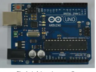
Fig. 1. Arduino microcontroller
support package. Battery powered and Bluetooth embedded system can be apply to Arduino later for wireless real time control application using IDE software after all parameters and uncertainties are being cleared.
II.METHODOLOGY
Arduino microcontroller linked with MATLAB/Simulink software was connected to different thicknesses of fabricated IPMC actuator. To make sure that IPMC actuation able to operate in both directions, H-bridge circuit was placed between the Arduino Pulse Width Modulation (PWM) output pins and IPMC actuator itself. The following details described the IPMC fabrication and experimental setup including Arduino microcontroller and Simulink model explanations. A.Fabrication of IPMC actuator
Fabrication of IPMC actuator is majorly divided into two parts; physical hot-pressing of Nafion membranes into different thicknesses and chemical electroless plating process (Fig. 2). IPMC performance is generally depends on its thickness, therefore we prepared two different thicknesses of IPMC which were t1 = 0.25 mm and t2 = 0.50 mm as actuators [9]. As explained by Fig. 2, physical hot pressing was being done by stacking several thin Nafion films altogether, then hot pressed by mold. Without pressure, temperature was raised to 150 °C for 20 minutes pre-heat, and then mold was pressed for 5 minutes at 15 MPa. After that every steps of hot pressing are same with the one explained by Sang Jun et al. except pre-heat and press parameters which require modification due to different mold used [10]. Once desired thickness achieved, Nafion membrane then underwent chemical electroless plating which involve pre-treatment, adsorption, reduction or primary plating, and secondary plating. We repeated the reduction process 3 times to improve platinum deposition in membrane surface which should resulted higher generative force [11]. Finally, membrane was immersed in LiOH solution to exchange H+ with Li+ to further increase IPMC generative force [12]. IPMC must be stored in DI water before use. B.Experiments setup
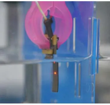
Both sides of fabricated IPMC actuator were vertically clamped by copper conducted clipper in cantilever configuration which connected to the Arduino PWM output pins 5 and 6 through H-bridge circuit as shown in Fig. 3. Only IPMC actuator was submerged underwater in this setup. For IPMC displacement feedback, Micro-Epsilon optoNCDT 1402
Fig. 2. IPMC fabrication
[image:2.595.90.248.56.174.2]Fig. 4. Simulink Model
-100 laser sensor will provide analog input value to the microcontroller. Real time control data logging can be provided by MATLAB/Simulink through ArduinoIO programming which already uploaded previously into Arduino memory.
In this setup Arduino analog read have default 10 bit resolution capability between 0 V and default analog reference voltage 5 V. Through voltage divider we set analog reference voltage to 2.1 V, thus improved default resolution of 4.90 mV to 2.05 mV per unit which was closed to 12 bit resolution. In theory it is capable to reach 14 bit resolution at a non-adjustable 5 V level where DAQ resolution normally ranged 12~16 bit. Due to the small IPMC actuator deflection, it is more than enough to read laser or another sensor input. While for sampling rate Arduino analog read capable to reach 10 KHz which is quite decent for inexpensive DAQ, but due to limitation when connected with Matlab/Simulink, for stable reading of multiple pins we are restricted to only 10 Hz. For analog write, we considered the default resolution is 8 bit through PWM ranging between 0 V to 5 V which is same as IPMC operation voltage range. PWM pins 5 and 6 have approximately 980 Hz frequency on default setting. This frequency can be adjusted and improved to suit certain application requirement by modifying timer option.
Simulink Model as shown in Fig. 4 is a closed loop model to control IPMC angular displacement. Dead zones provide a platform to allow H-bridge circuit to be realized. This means polarities of Arduino PWM output pins 5 and 6 depend on whether positive or negative input being supplied. Therefore IPMC can be control to the both directions.
C.Measured performance
The objective of performed experiments is to study the feasibility of Arduino microcontroller usage with IPMC actuators. Figure 5 shows a clamped 20 mm × 8 mm IPMC actuator with thickness, t (t1 = 0.25 mm, t2 = 0.50 mm) in the cantilever configuration submerged underwater. The laser sensor pointed approximately at 10 mm of IPMC actuator height.
Before actual experiments were conducted, a step signal was supplied as desired IPMC actuator angular displacement to each actuator thickness for PID parameters tuning. As the performance of IPMC is greatly depends on its thickness, PID parameter for each IPMC was expected to be different. Instead of straight forward displacement we set angular displacement as input and output due to the fact that, this feasibility study result is going to be use by IPMC angular displacement feedback based control in later project. Figure 6 suggests that thicker IPMC which required higher proportional controller value have lower response speed. As explained throughout many journals, thicker IPMC added with bigger Lithium cation effect will produce slower response speed, trade-off with actuation force improvement [1, 2].
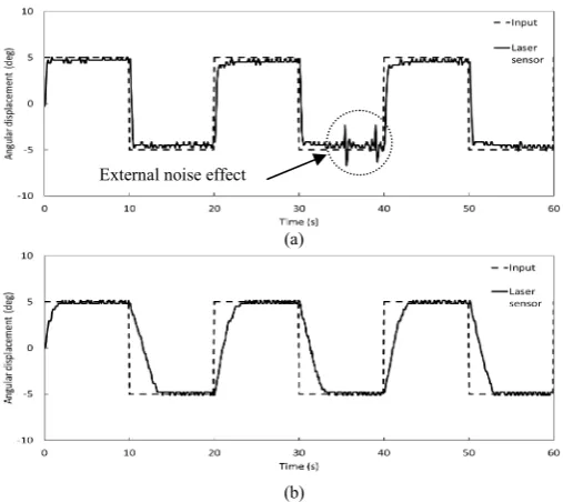
[image:3.595.33.560.55.245.2]For the first experiment, square wave of 0.05 Hz with amplitude ranging between ± 5 degree was supplied to the closed loop of Simulink model for both IPMC thicknesses. Our target was to measure steady-state tracking for low frequency square wave using Arduino. Then in the second experiment square wave was replaced by sinusoidal wave and all experiments were repeated for low and high frequencies.
[image:3.595.348.531.514.688.2](a)
[image:4.595.37.292.58.276.2](b)
Fig. 6. PID controller tuning results for different IPMC actuator thicknesses (a) IPMC t1 (b) IPMC t2
III.RESULTS AND DISCUSSION
[image:4.595.307.561.341.567.2]A.Steady-state response of control system
Figure 6 shows both tunings achieved critically damped response without overshoot in different period of times. IPMC t1 delay time is approximately 0.2 s while IPMC t2 recorded 0.45 s. Besides, IPMC t2 shows a response with significantly required more settling time, 1.6 s, compared to the IPMC t1 with 0.3 s settling time. It is worth noted that steady-state tolerances for angular displacement for both IPMCs are set differently due to unique noises applied to each of IPMC thickness. For IPMC t1, we consider that a response reach steady-state condition when it reaches and stay within a range of -12 % to 1 % target value, while IPMC t2 is between ± 3 %. This phenomenon is believed to be caused by nonlinearities associated with IPMC actuator and the control system noise itself. Moreover, the wider steady-state tolerances range for thinner IPMC also can be explained by higher effect of back relaxation compensation action. Back relaxation effect is the IPMC actuator relaxation action towards opposite direction of actuation when subjected to voltage [13]. This effect need to be compensated by counter-direction of voltage in order to maintain certain IPMC actuator position, thus produces some extra oscillation signal during steady-state condition especially to the low frequency application. Lower Arduino analog read sampling rate and analog write resolution setup also are considered factors to the unsmoothed signal reading.
First experiment results are described in Fig. 7. Response characteristics are almost identical as have been explained for tuned step responses in Fig. 6. IPMC t1 response tends to be easily affected by external noise such as vibration compared to the IPMC t2 as shown in the Fig. 7(a). This is maybe due to its inability to contain excessive external noise fluctuation owing to lower capacitance of thinner IPMC.
B.Tracking performance with different frequencies and thicknesses
The tracking performance of IPMC actuator using Arduino microcontroller is further verified by comparing emax(t) and
erms(t) from measured tracking results when IPMC t1 and t2
subjected to 0.5 and 0.05 Hz sinusoidal wave input as shown in Fig. 8 and Fig. 9. As been defined by Eq. 1 and Eq. 2, emax(t)
represents maximum error percentage from each tracking error percentage, e(t) for all read laser sensor data when comparing with input signal, whereas erms(t) describes general error
percentage over total acquisition time. Table I stated the calculated maximum tracking error, emax(t) and
root-mean-squared tracking error, erms(t) for both IPMC thicknesses and
frequencies. For lower thickness of IPMC, low frequency tracking signal exhibit external noise effects due to IPMC lower capacitance, similar with square wave experiment result. These external noise effects cause emax(t) in Fig. 8(a) recorded
53.99 %, even though its erms(t) is only 5.64 %. Whereas, Fig.
9(a) shows the most fitting tracking signal which only contains 8.40 % and 3.12 % of emax(t) and erms(t) respectively.
For higher frequency, IPMC t1 responded quite well with relatively lower root-mean-squared tracking error compared to IPMC t2. This is because IPMC t1 have higher response speed than IPMC t2.
(a)
(b)
Fig. 7. Tracking results for square wave 0.05 Hz reference input (a) IPMC t1 (b) IPMC t2
(a)
[image:4.595.308.562.605.714.2](b)
Fig. 8. IPMC t1 tracking responses to sinusoidal waves (a) 0.05 Hz (b) 0.5 Hz
(a)
(b)
[image:5.595.32.293.620.687.2]Fig. 9. IPMC t2 tracking responses to sinusoidal waves (a) 0.05 Hz (b) 0.5 Hz
TABLE I. TRACKING ERRORS COMPARISON
Input wave
IPMC t1 IPMC t2
0.05 Hz 0.5 Hz 0.05 Hz 0.5 Hz
emax erms emax erms emax erms emax erms
Sine 53.99a 5.64 28.46 12.01 8.40 3.12 53.35 28.70 a. 97% of errors are below 10%, emax(t) high due to effect of external noise.
C.Current Arduino setup capability and limitation
Based on above results, we can consider that for lower frequency response Arduino manage to clearly differentiate the steady-state response for both thicknesses of IPMCs. The response performance such as speed and stability can be acquired through current Arduino setup. Moreover this setup also is accurate enough to allow us to calculate the tracking error between IPMCs which subjected to different frequencies of sinusoidal wave input. These capabilities prove that Arduino microcontroller is capable to replace expensive and bulky DAQ device when associate with IPMC actuator control and analysis.
However there are several improvements need to done especially to improve the steady-state noise which we assumed contributed by 2 main factors; IPMC actuator mechanism and current setup limitation for Arduino microcontroller. Details on noise caused by IPMC are already explained before. For Arduino current setup analog read, even though 12 bit resolution is on par with common DAQ device, it is obvious that current sampling rate (10 Hz) of analog read is not enough to precisely tracking the small angular displacement. It is sensible to have minimum sampling rate of 100 Hz by limiting the usage of analog read pins. Besides, instead of MATLAB/Simulink, open source and light softwares such as Processing and PLX-DAQ can be used for data logging which ultimately allow Arduino to achieve near to its maximum 10 KHz sampling rate. To further improve the sampling rate in the IPMC control system, instead of using Simulink model, microcontroller coding can be done directly using official Arduino environment called Arduino IDE. Besides that, improving analog write to higher resolution through timer option also might decrease the noise especially to the thinner IPMC subjected to low frequency.
IV.CONCLUSION
This paper presented the feasibility studies of Arduino microcontroller usage to control IPMC actuator. Arduino is low-cost, small and flexible open source microcontroller compared to the existing high price and bulky DAQ device which is not suitable for particularly small size control system involving IPMC actuator. A closed loop with laser sensor as feedback running by MATLAB/Simulink model navigate the tracking experiments using different reference input waves, wave frequencies and IPMC thicknesses. Tracking results show that Arduino able to portrays the response speed, stability and tracking error of IPMC actuators. Based on Arduino data acquisition, thinner IPMC (t1) have more than 5 times respond speed than thicker IPMC (t2). However IPMC t1 have lower steady-state stability (higher noise) compared to IPMC t2 due to IPMC actuator mechanism and current setup limitation for Arduino microcontroller. For error over total acquisition period, IPMC t2 with lower frequency reference input shows minimum error (erms 3.12 %), while IPMC t2 with
higher frequency contains highest error (erms 28.70 %).
Therefore, we can conclude that, with improvements in term of analog read sampling rate and analog write resolution, Arduino microcontroller has capability to accurately control (1)
and analyse the IPMC actuator, thus manage to replace expensive and bulky current DAQ hardware for small autonomous device.
ACKNOWLEDGMENT
Authors gratefully acknowledge support from the Ministry of Higher Education (MOHE), Malaysia for their ERGS 2011 grant sponsorship, Universiti Teknologi Mara (UiTM) Young Lecturer Scheme Fellowship for the personal financial sponsorship and Universiti Sains Malaysia (USM) for their technical and facilities support.
REFERENCES
[1] B. Bhandari, G.-Y. Lee, and S.-H. Ahn, "A review on IPMC material as actuators and sensors: Fabrications, characteristics
and applications," International Journal of Precision
Engineering and Manufacturing, vol. 13, pp. 141-163, 2012.
[2] W.-S. Chu, K.-T. Lee, S.-H. Song, M.-W. Han, J.-Y. Lee, H.-S.
Kim, et al., "Review of biomimetic underwater robots using
smart actuators," International Journal of Precision
Engineering and Manufacturing, vol. 13, pp. 1281-1292, 2012.
[3] K. Mallavarapu and D. J. Leo, "Feedback Control of the
Bending Response of Ionic Polymer Actuators," Journal of
Intelligent Material Systems and Structure, vol. 12, pp. 143-155,
2001.
[4] R. C. Richardson, M. C. Levesley, M. D. Brown, J. A. Hawkes, K. Watterson, and P. G. Walker, "Control of ionic polymer
metal composites," Mechatronics, IEEE/ASME Transactions on,
vol. 8, pp. 245-253, 2003.
[5] Z. Chen and X. Tan, "A Control-Oriented and Physics-Based Model for Ionic Polymer--Metal Composite Actuators,"
Mechatronics, IEEE/ASME Transactions on, vol. 13, pp.
519-529, 2008.
[6] K. K. Ahn, D. Q. Truong, D. N. C. Nam, J. I. Yoon, and S. Yokota, "Position control of ionic polymer metal composite
actuator using quantitative feedback theory," Sensors and
Actuators A: Physical, vol. 159, pp. 204-212, 2010.
[7] Z. Chen, K.-Y. Kwon, and X. Tan, "Integrated IPMC/PVDF sensory actuator and its validation in feedback control,"
Sensors and Actuators A: Physical, vol. 144, pp. 231-241, 2008.
[8] K. K. Leang, S. Yingfeng, S. Sisi, and K. J. Kim, "Integrated Sensing for IPMC Actuators Using Strain Gages for
Underwater Applications," Mechatronics, IEEE/ASME
Transactions on, vol. 17, pp. 345-355, 2012.
[9] B. Kim, B. M. Kim, J. Ryu, I.-H. Oh, S.-K. Lee, S.-E. Cha, et
al., "Analysis of mechanical characteristics of the ionic
polymer metal composite (IPMC) actuator using cast
ion-exchange film," in Proc. SPIE, pp. 486-495, 2003.
[10] L. Sang Jun, H. Man Jae, K. Seong Jun, J. Jae Young, L. Ho Young, and K. Yong Hyup, "A new fabrication method for
IPMC actuators and application to artificial fingers," Smart
Materials and Structures, vol. 15, p. 1217, 2006.
[11] T. Nakamura, T. Ihara, T. Horiuchi, T. Mukai, and K. Asaka, "Measurement and Modeling of Electro-Chemical Properties of Ion Polymer Metal Composite by Complex Impedance
Analysis," SICE Journal of Control, Measurement, and System
Integration, vol. 2, pp. 373-378, 2009.
[12] S.-G. Lee, H.-C. Park, S. D. Pandita, and Y. Yoo, "Performance Improvement of IPMC (Ionic Polymer Metal Composites) for a
Flapping Actuator," International Journal of Control,
Automation, and Systems, vol. 4, pp. 748-755, 2006.
[13] J. F. Maxwell, J. K. Kwang, and K. L. Kam, "Mitigating IPMC back relaxation through feedforward and feedback control of
patterned electrodes," Smart Materials and Structures, vol. 21,