STEERABLE ARRAY ANTENNA
N. A. Salleh, N. Abdullah and E. Mohd
Department of Communication Engineering, Faculty of Electrical and Electronic Engineering, Universiti Tun Hussein Onn Malaysia, Johor, Malaysia
E-Mail: [email protected]
ABSTRACT
This paper presents the design of an electronically steerable array antenna. An adaptive antenna using a slotted patch antenna for WLANs operated at 2.4 GHz is proposed. The designed antenna has five elements array, one for active elements and the remaining four are passive elements which connected to the variable reactance circuit. The variable reactance value will vary the beam pattern of the antenna. For the simulation, OFDM signal is used for the incoming signal and interference. Correlation between HGI and TGI is calculated as an objective function of the algorithm. A downhill simplex algorithm is used to maximize the cost function. From numerical simulation, null is performed for the incoming interference.
Keywords: steerable, slotted antenna, downhill simplex method algorithm, interference.
INTRODUCTION
In land mobile communication, there is no clear line of sight (LOS) between transmitter and receiver especially for moving systems. The receiver might receive the reflected signals instead of the original signal. The LOS is often blocked by obstacles which will lead the signal to be reflected as shown in Figure-1. The received signal is a combination of refracted signal, attenuation signal, reflected signal and diffraction signal. This effect is known as multipath fading effects. The carrier to noise ratio (CNR) is degraded because of multipath effects.
Figure-1. Multipath effects.
Besides that, signal to noise ratio (SNR) also degraded because of frequency selective fading in multipath fading effects. Due to those effects, the transmission quality is definitely degraded. Therefore, Sklar has introduced several techniques to mitigate the effects of multipath fading (Sklar, 1997). In order to eliminate the distortion caused by frequency selective
fading, he has proposed to use an adaptive equalization, spread spectrum, and pilot signal. He also suggested several types of diversity to overcome the loss effects caused by flat fading and slow fading.
Nowadays, many researches on smart antenna has been conducted. Smart antennas are an array antenna that can steer the beam toward the desired signal and eliminate the undesired signal (interference). There are two types of adaptive array antennas; switched beam array and adaptive beamforming antenna. Switched beam array antennas are antennas that only controlled the direction of maximum radiation. This antenna offers fixed beam direction. Meanwhile, the adaptive beamforming antennas controlled the radiation in all directions.
Adaptive array antenna is the best candidate to overcome this phenomenon (Godara, 1997). Harrington has design a reactively steerable adaptive array (RSAA) using dipole antenna. This antenna is an adaptive array with single receiver. For reactively controlled antenna array, the beam pattern is controlled by varying the reactive loads. By optimizing the gain, we are able to steer the beam toward the maximum gain direction which is the desired signal (Harrington, 1978). Many studies has been conducted for adaptive beamforming antenna. These array antennas are consisting of several radiating elements such as a dipole or patch. These antennas have serious problems such as a bulky structures and a large amount of calculation because of blind algorithm (Cheng (2001), Schlub (2003), Vlasis (2008) and Abdullah (2010)).
ANTENNA DESIGN
Antenna configuration
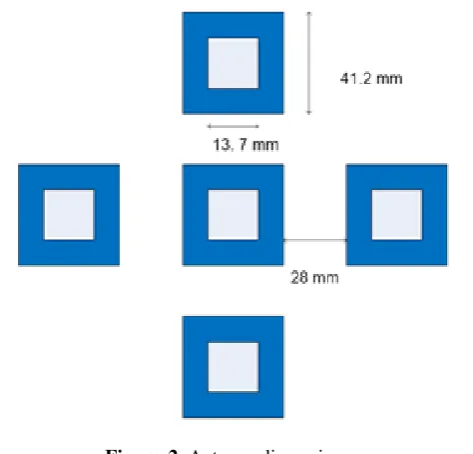
[image:2.595.53.290.225.452.2]The simulation for the slotted antenna is carried out by using CST. The designed antenna consists of 5 elements. The size for each element is 41.2 mm x 41.2 mm with 13.7 mm x 13.7 mm slotted at the middle of the patch as shown in Figure-2.
Figure-2. Antenna dimensions.
Description of simplex method
This section will describe about the downhill simplex method. It is an iterative search technique to minimize a function that is nonlinear in parameters. This method also known as Nelder-Mead method. The advantage of using Simplex method is it can be used to solve N-dimensional geometry. Simplex is a geometrical figure consisting N dimensions of N+1 points and all interconnecting line segments and polygonal faces. For example, in two dimensional, simplex is viewed as triangle.
Simplex method starts with defining, P0 which is consists of N+1points. After that all points in P0 will be
classified to highest point (
x
h), second highest point (x
sh) and lowest point (
x
l). Simplex method has several possible steps such as reflection, expansion, contraction and multiple contractions as shown in Figure-3. All this steps are required in order to discard the highest point.The process starts by reflecting the highest point,
x
h to anew point denoted as,
x
r. Pointx
r is defined ash
r x x
x (1
)
(1)Where,
is a reflection coefficient, andx
is a centroid point defined as
M
i i
x M x
1
1
i
h
(2)If PlPrPsh , then replaced
x
h withx
r and start the new process again. If PrPl , then there ispossibility to find new minimum point. Therefore, the
x
rpoint is expanded along the same direction using the following equation,
x
e) (x x x
xe r (3)
Where, is an expansion coefficient and greater
than one
(
1
)
. If PePh , then replacedx
h withx
eand repeat the process again. However, if
P
e is greater orequal to
P
h , then new simplex is formed by replacingx
hby
x
r and continue the process.If the reflection process leads the
P
r to begreater than
P
h , then contraction is performed using the following equation,)
(
x
x
x
x
c
h
(4)Figure-3. Downhill simplex method (Press).
Implementation of simplex method
In this study, Orthogonal Frequency Division Multiplexing (OFDM) signal is used as an incident and delayed signal. HGI is placed at the head of the symbol. The correlation between HGI and TGI should be one because HGI is a copy of TGI.
Figure-4. OFDM signal.
Figure-4 shows the main signal, delayed signal, and received signal. The correlation between HGI and TGI is calculated using equation (5).
� = |∑ �� � + ∗|
√|∑ �� � ∗|√|∑ � + � +� ∗| (5)
where y(n) denotes the sampled signal of y(t), and m denotes the sampled time interval between HGI and TGI. If the correlation between HGI and TGI of the received signal becomes large, the delayed signal has to be cancelled. The correlation between HGI and TGI is used as an objective function.
Figure-5. Concept of proposed antenna.
RESULTS AND ANALYSIS
Spatial cross correlation
Spatial cross correlation (SCC) is calculated by using equation 6 using MATLAB. The SCC must be less than 0.5 in order to ensure the capability of the antenna to operate as diversity antenna. From simulation, the SCC for each pair of ports are less than 0.5 as tabulated in Table-1.
��� = √ |∫ ∫ �∗
�
� �,� � �,� ����|
∫ ∫ �� � ∗�,� � �,� ���� ∫ ∫ �� � ∗�,� � �,� ���� (6)
Table-1. Simulated spatial cross correlation.
Port 1 2 3 4 5
1 0.1058 0.0982 0.1128 0.2062
2 0.1058 0.0495 0.0397 0.1112
3 0.0982 0.0495 0.0079 0.0857
4 0.1128 0.0397 0.0079 0.0570
5 0.2062 0.1112 0.0857 0.0570
Adaptive beamforming
the designed antenna is depicted in Figure-5. The simulation starts by calculating the correlation coefficient between HGI and TGI. Then, it searches for the minimum value of the cost function and sends the new reactance value to each port of the passive elements. The reactance value will changed the beam pattern of the antenna. The parameter listed in Table-2, are used in the simulation. For the modulation schemes, OFDM signal is used. In this simulation, two signals (the desired signal and the interference) are used, both signals are assumed to have same amplitude and incident from random directions.
Table-2. Simulation parameters.
Modulation OFDM
No. of signals 1 desired signal 1 interference
Amplitude 1
Direction of arrival (DOA)
0°, 90° 0°, 210°
Figure-6 shows the beam pattern from two scenarios where the desired and interference are randomly selected. The red arrow represents the incoming interference and the desired signal is represented by the blue arrow. The simulation demonstrates that the proposed antenna can eliminate the incoming interference. As can be observed, null is performed for the interference coming from 90° and 210°.
(a) DOA 0°, 90°
(b) DOA 0°, 210°
Figure-6. Beam pattern from MATLAB simulation.
By varying the reactance values, the interference can be eliminated. The reactance values are different for each interference. The reactance value for two DOAs can be referred to Table-3. For the interference coming from 90°, it took 0.0623 s to convergence the signal with 51 iterations, with SINR 15.1 dB. For the interference coming from 210° the time required to converge the signal is 0.0494 s with 38 iterations with SINR 33.76 dB.
Table-3. Simulation results.
DOA Convergence time (s)
Iteration
number Reactance values (Ω)
CONCLUSIONS
A steerable antenna has been designed, modelled in this paper. The simulated results have been presented and discussed. The antenna is modelled using a slotted patch antenna. This designed antenna has SCC less than 0.5 for a better diversity performance. From MATLAB simulation, the designed antenna is capable to eliminate incoming interference and steer towards the desired signal. The beam of the antenna is controlled by reactance value which was calculated using downhill simplex method algorithm.
ACKNOWLEDGEMENT
This work is supported by Universiti Tun Hussein Onn Malaysia short term grant, Vot no. 1327.
REFERENCES
Abdullah N., and Kuwahara Y. 2010. A Study of ESPAR Antenna. International Conference on Microwave and Millimeter Wave Technology 2010, pp. 1999-2002.
Cheng. J, Kamiya Y. and Ohira T. 2001. Adaptive beamforming of ESAPR antenna based on steepest descent gradient algorithm, IEICE Transaction on Communication, E84-B (7), pp. 1790-1800.
Godara L. C. 1997. Application of antenna array to mobile communications, part 1: Performance improvement, feasibility, and systems considerations. Proc. IEEE, 85(7), pp. 1031-1060.
Harrington R. F. 1978. Reactively controlled directive arrays. IEEE Transaction on Antennas and Propagation, AP-26(3), pp. 390-395.
Nelder J. A and Mead R. 1965. A simplex method for function minimization. Computer Journal, 7(4), pp. 308-313.
Press W. H., Teulkolsky S. A., Vetterling W. T., and Flannery B. P. Numerical recipes in C; The Art of Scientific Computing. Cambridge University Press, Second Edition, pp. 408-411.
Schlub R., Wei J., and Ohira T. 2003. Seven-element ground skirt monopole ESPAR antenna design from a genetic algorithm and the finite element method. IEEE transaction on Antennas and Propagation, 51(11), pp. 3033-3039.
Sklar B. 1997. Rayleigh fading channels in mobile communication systems Part 2: Mitigation. IEEE Communication Magazine, pp. 102-109.