SERIES 60 (LEVEL 68)
MULTICS PROGRAMMERS'
MANUAL-SUBSYSTEM WRITERS' GUIDE
SUBJECT
Reference Guide for Advanced Multics Users Writing Their Own Subsystems
SPECIAL INSTRUCTIONS
This manual is one of six manuals that constitute the Multics Programmers'
Manual (MPM). Reference Guide
Commands and Active Functions Subroutines
Subsystem Writers' Guide Communicatons Input/Output Peripheral Input/Output
Order No. AG91 Order No. AG92 Order No. AG93 Order No. AK92 Order No. CC92 Order No. AX49
This manual supersedes AK92, Rev. 1 dated September 1975, and its addenda (Addendum A dated July 1976, Addendum B dated February 1977, and Addendum C dated November 1977). Except in the areas where there have been extensive revisions, such as an entirely new command or subroutine, marginal change indicators have been included in this edition.
SOFIWARE SUPPORTED
Multics Software Release 7.0
-ORDER NUMBER
PREFACE
Primary reference material for user and subsystem programming on the Multics system is contained in six manuals. The manuals are collectively referred to as the Multics Programmers' Manual (MPM). Throughout this manual, references are frequently made to the MPM. For convenience, these references will be as follows:
Document
Reference Guide (Order No. AG91)
Commands and Active Functions (Order No:-AG92)
Communications Input/Output (Order No. CC92)
Subroutines (Order No. AG93)
Subsystem Writers' Guide (Order No. AK92)
Peripheral Input/Output (Order No. AX49)
Referred To In Text As
MPM Reference Guide
MPM Commands
MPM Communications I/O
MPM Subroutines
MPM Subsystem Writers' Guide
MPM Peripheral I/O
The MPM Reference Guide contains general information about the Multics command and programming environments. It also defines items used throughout the rest of the MPM. And, in addition, describes such subjects as the command language, the storage system, and the input/output system.
The MPM Commands is organized into four sections. Section 1 contains a
*
list of the Multics command repertoire. arranged functionally. Section 2 describes the active functions. Section 3 contains descriptions of standard Multics commands, incluolng the calling sequence and usage of each command. Section 4 describes the requests used to gain access to the system.The MPM Peripheral I/O manual contains descriptions of commands and subroutines used to perform peripheral I/O. Included in this manual are commands and subroutines that manipulate tapes and disks as I/O devices.
The MPM Communications I/O manual contains information about the Multics communications system. Included are sections on the commands, subroutines, and I/O modules used to manipulate communications I/O. Special purpose communications I/O, such as binary synchronous communication, is also included.
(£)
Honeywell Information Systems Inc., 19797/81
The MPM Communications I/O manual contains in formation about the Mul tics communications system. Included are sections on the commands, subroutines, and I/O modules used to manipulate communications I/O. Special purpose communications I/O, such as binary synchronous communication, is also included.
The MPM Subroutines is organized into three sections. Section 1 contains a
1 ist of the subroutine repertoire, arranged functionally. Section 2 contains descriptions of the standard Multics subroutines, including the declare statement, the calling sequence, and usage of each. Section 3 contains the descriptions of the I/O modules.
The MPM Subsystem Writers' Guide is a reference of interest to compiler writers and writers of sophisticated subsystems. It documents user-accessible modules that allow the user to bypass standard Multics facilities. The interfaces thus documented are a level' deeper into the system than those required by the majority of users.
Examples of specialized subsystems for which construction would require reference to the MPM Subsystem Writers' Guide are:
• A subsystem that precisely imitates the command environment of some system other than Multics.
• A subsystem intended to enforce restrictions on the services available to a set of users (e.g., an APL-only subsystem for use in an academic class) .
• A subsystem that protects some kind of information in a way not easily expressible with ordinary access control lists (e.g., a proprietary linear programming system, or an administrative data base system that permits access only to program-defined, aggregated information such as averages and correlations).
The MPM Subsystem Writers' Guide provides the advanced Multics user with a selection of some of the internal interfaces used to construct the standard Multics user interface. It also describes some specialized tools helpful to the advanced subsystem writer.
The facilities described here are subject to changes and improvements in their inter face specifications. Further, at the level of the system presented by many of these inter faces, it is d ifficul t to avoid far-reaching sub system changes when these interfaces change. Thus, the subsystem writer is cautioned against the unnecessary use of the interfaces described in this manual.
Most interfaces described here should be used only if there is a need to bypass normal Mul tics procedures; i.e., in using one of these interfaces, the user risks giving up some of the desirable characteristics of Mul tics. For ex ample, the stand ard Mul tic s inter face pr esents a con si stenc y of styl e and interpretation to the user that the subsystem writer may find difficul t to duplicate and maintain. Therefore, the subsystem writer should be cautious about unintentionally introducing different, and possibly confusing, styles and interpretations when bypassing a standard function.
Several cross-reference facilities in the MPM help locate information:
• Each manual has a table of contents that identifies the material (either the name of the section and subsection or an alphabetically ordered list of command and subroutine names) by page number.
• Each manual contains an index that lists items by name and page number.
Changes and Additions to MPM Subsystem Writers' Guide, AK92, Rev. 2, Addendum ~
The following subroutine and entry point descriptions are new to this manual and do not contain change bars.
get external variable hcs-$get uid-seg -msf-manager lmsf get ptr reaa password $switcn set ext variaole
set ext variable $locate sus-signal handler
sus-signal-handler-~reconnect ec enable sus=signal=handler-$reconnect=ec=disable
The signal command is new to this manual and does not contain change bars.
The display component name and list external xterna inadvertently omitted from the previous addendum.
ariables commands were are included in this addendum, and do not contain change bars~
The mode_string_ subroutine has been moved to the MPM Subroutines manual.
The following subroutine and entry point descriptions are obsolete and have been deleted.
convert ipc code
resource control-$assign resource=control=$get_status
resource control $set status resource=control-$unassign
Throughout this manual change bars indicate technical additions and ch8nges, and asterisks indicate deletions.
Section 1
Section 2
CONTENTS
Mul tics Standard Object Segment . . Format Of An Object Segment
Structure of the Text Section Entry Sequence . . . . . . .
Gate Segment Entry Point Transfer Vector Structure of the Definition Section
Definition Section Header .
Expression Word . . . . Type Pair . . . . . . . . Trap Word . . . . Initialization Structure for Type 5
system and Type 6 Links
Definition Hash Table . . . . Structure of the Static Section Structure of the Linkage Section
Linkage Section Header
Internal Storage Area . . . . Links . . . .
First-Reference Trap . . . . Structure of the Symbol Section
Symbol Block Header . . .
Source Map . . . . Relocation Information . . . . .
Structure of the Object Map . . . . Generated Code Convent ions . . . .
Text Section . . . . . . Entry Sequence . . . . . . . . Tex t Reloca t ion Codes . . . . Definition Section
Definition Relocation Codes Implicit Definitions
Lin k age Se c t ion . . . . Internal Storage . . Links . . . . . . .
Linkage Relocation Codes . Static Sec tion
Symbol Section
Structure of Bound Segments . . . Internal Link Resolution
Definition Section
Binder Symbol Block . . . Bind Map . . . . Standard Execution Environment
Standard Stack and Link Area Formats . Multics Stack
Stack Header . . . . Multics Stack Frame . .
Linkage Offset Table
Internal Static Offset Table Subroutine Calling Sequences 0
Call Operator .
Entry Operator . . . . . . . Push Operator . . . . .
Return Operator .
Short Return Operator . . . . Pseudo-op Code Sequences . . . Register Usage Conventions
Page 1-1 1-1 1-2 1-~ 1 -4 1-4 1-7 1-10 1-10 1-12 1-12 1=14 1-15 1-15 1-16 1-17 1-17 1-1P 1-20 1-20 1-22. 1 1-2 ~
1-?!:i 1-27 1-27 1-27 1-2P 1-20 1-2 <:
Section 3
Section 4
Section 5
Section 6
7/82
CONTENTS (cont)
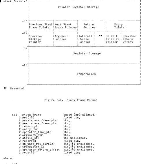
Arg ument Li st Format . . . . Parameter Descriptors .
Closed Subsystem Programming Environment Writing a Process Overseer . . . .
Process Initialization . . . .
Some Notes on Writing a Process Overseer Direct Process Overseers . . . . Handling of Ouit Signals
Implementation Of Input/Output Modules
I/O Control Blocks . . . . I/O Control Block Structure . . . . At t a c h Po in t e r s . . . . . Open Pointers . . . . Entry Variables . . . . . . Synonyms . . . . . .
Writing an I/O Module Design Considerations .
Implementation Rules . . . . Attach Operation . . . . Open Operation . . . . Close Operation . .
Detach Operation . . . .
Modes and Control Operations . . . . Performing Control Operations From
Command Level . . .
Other Operations . . . . Outer Modules . . . . Reference to Commands and Subrou~ines by
Function . . . . . . Command Repertoire . . . . Subroutine Repertoire
Commands . . . .
Command Description Format . aIm . . . . . . . . .
aIm abs, aa . . . . . . arcnive sort, as . . . . area stitus . . . . . . . . . copy-switch off, csf . . . . .
copy-swi tch-on, c sn . . . . . . . create area-. . . • . delete-external variables, dev . . . delete-volume quota . •
dial manager call . . . . . . .
dispTay component name, dcn . . . . list external varTables, lev
list-temp segments mbx create, mbcr
mbx-delete acl, mbda . . . . mbx-list acl, mbla .
mbx-set acl, mbsa . . . print bTnd map, pbm .
print-link-info, pli . . . . . . print-linkige usage, plu . . . . reorder archive, ra . . . . reset external variables, rev.
set dTr ring brackets, sdrb .
set-max-length, swl . . . . . . . set-ring brackets, srb . . . .
set-system storage . . . . set-user storage
signal vi Page 2-13 2-1P ~-1 3-1 3-1 3-5
?-5
3-5 Ll-1 4-1 4-2 4-3 4-3 4-4 4-4 4-4 4-4. 1 Ll-5 1.!-6 4-7 1.1-7 4-8 LI_P 4-8 Ll-10 1I-11 5-1 5-1 5-j 6-1 6-1 6-4 6-30 6-32 6-33 6- 34. 1 6-34.2 6-356-36
6-37 6-38 6- 39. 1 6-39.2 6-1~ 0
~-4 3 6-45 ~-48 6-50 6-56 6-57 6-59 6-60 6-62 6-63 6-64 6-66 ~_~7
\.. - ~j ,
Section 7
CONTENTS (cont)
Subroutine Descriptions . • . . . . . active fnc err . . . .
actIve Tnc err $suppress name . . . . add epilogue nandler ~ . . . .
aim-check .- . • . . -.
aim check $equal . . . • . aim-check-$greater . . . . aim-check-$greater or_equal. area info .- . . . . ~ . • . asciI to ebcdic . . . . . .
ascii-to ebcdic . . . . ascii-to-ebcdic-$ae table . assign • • . • . . • . .
assIgn $computational assign-round
assign-truncate change deTault wdir
char to numeric - . . .
chec~ s~ar name- . . . • • . . • . . • • check s~ar name $path • . . . • . • . . . check-star-name-$entry . . . . componen~ info • -. . . • .
component info $name
component-info-$offset . . . • condition in~erpreter . • • . continue ~o signal - . • . .
convert aim-attributes . • . . convert-diaT message . • . . • • .
convert dIal message $return io module convert status code . ~ . . . ~
.-copy acT • . • . . . . • . crea~e ips mask . . • . . cross ring- - . • . . cross-ring-io $allow cross .
cv bin - -
--cv Din $dec . cv-bin-$oct cv dec -cv-dec-check cv-dir-mode -. cv-entry
cvhex -cv-hex-check cv-mode cv-oct
cv-oct-check
cv-ptr- • • . . -cv ptr $terminate .
cv rcp at~ributes . • • • . . -cv rcp attributes $to string
cv-rcp-attributes-$from string . . . cv-rcp-attributes-$modiTy . . • . • . . . cv-rcp-attributes-$from string reI
cv-rcp-attributes-$modiTy reI ~ . . . . . cv-rcp-attributes-$reduce-implications cv-rcp-attributes-$protec~ed change . cv-rcp-attributes-$test valia . . . . cv userid- . . . • .-. • .-. . • . . . decode descriptor . . • . .
define-area - . . • . . . • • • . . . . dial manager . . . . dTal manager $allow dials . • • . • . . . dial-manager-$regis~ered server
dial-manager-$dial out - • • . . dial=manager=$release_channel .
7/82
CONTENTS (cont)
dial manager $release channel no hang up . dial-manager-$release-no listen: .
dial-manager-$shutoff-dials . . . . dial-manager-$release-dial id . . dial-manager-$privileged a~tach . • . dial-manager-$tandd attach . . . dial-manager-$terminate dial out
dl handTer . : . . . . --dl handTer . • . . • • .
dl-handler-$dblstar . . dl-handler-$dirdelete • .
dprin~ . . : . . .
dprlnt . . . • . . . • . . . • dprint-$check daemon access . . • . . dprint-$queue-conten~s
dump segment .- . . .
ebcdic to ascii . . • . . . ebcaic-to ascii . . .
ebcdic-to-ascii-$ea table • . . . . . execute epilogue -
-find condition frame
find-condition-info - • • . get aefault wdir
getdefinitlon -get-entry arg aescs .
get entry arg'descs . . get-entry-arg-descs-$info .
get-entry-arg-descs-$text only • . get-entry-arg-descs-$text-only info • get entry name - • . . - . • • - • . : • . . get-entry-poin~ dcl
get en~ry pOlnt dcl get equal name .- . . - . . get-equal-name-$component get-external variable get-lock id -. • . . : get-privileges
get-ring • • - . • . . get-system free area
hasn index- • --:- . . . • • • hcs ladd dir inacl entries . hcs-$add-inacl entries . • •
hc s-$del-d ir tree • . . • . . . • . . hcs-$delete dir inacl entries
hcs-$delete-inacl entries hcs-$force write: • • • . . hcs-$get author . . • . .
hcs-$get-bc author . • . . . • • . hcs-$get-dir ring brackets . . • • • . . hcs-$get-exponent-control . • . .
hcs-$get-ips mask- . • • • • • • . hcs-$get-linK target • • •
hcs-$get-max Tength
hcs-$get-max-length seg • • • . • hcs-$get-process usage •
hcs-$get-ring brackets • hcs-$get-safe~y sw . . hcs-$get-safety-sw seg . hcs-$get-search-ruTes
hcs-$get-system-search rules hc s-$get-uid seg . • . -. . . hcs-$get-user effmode
hcs-$ini~iate-search rules hcs-$list dir-inacl -.
hcs=$list=inacl • . . . viii Page 7-50 7-50 7-51 7-51 7-51 7-52 7-52 7-54 7-54 7-55 7-55 7-55.1 7-55. 1 7-55.4 7-55.6 7-56 7-57 7-57 7-57 7-59 7-60 7-61 7-62 7-63 7 -63. 1 7-63. 1 7-63.2 7-63.3 7-63.4 7-64 7-64. 1 7-64. 1 7-65 7-66 7-66.2 7-67 7-68 7-70 7-71 7-71.1 7-72 7-74 7-76 7-77 7-78 7-80 7-81 7-82 7-83 7-83. 1 7-83.2 7-84 7-85 7-86 7-86. 1
CONTENTS (cont)
hcs $quota move
hcs-$quota-read • . • .
hcs-$replace dir inacl . . . • . hcs-$replace-inacl . . .
hcs-$reset ips mask •
hcs-$set automatic ips mask . . • . •
hcs-$set-dir ring bracKets . . . • . . . . • hcs-$set-entry bound • . • .
hcs-$set-entry-bound seg . . • • . hcs-$set-exponent control . . . . hcs-$set-ips mask- . • • •
hcs-$set-max-length • • . . hcs-$set-max-length seg . . . • . hcs-$set-ring brackets .
hcs-$set-safe~y sw • . . • • • . hcs-$set-safety-sw seg . . • • . hcs-$star . • -:- .- . • • • • • .
ncs $s~ar list hcs-$star-dir Tist hcs $wakeup
help . . . • help $init help- . • •
help-$check info segs help-$term - . • -:- . • •
interpret resource desc . • . • iod info - . . • . - . . -:- . . . • •
lod info $generic type . . . . • • iod-infO-$driver access name . . . • . . iod-info-$queue aata - . . . • • • iod-info-$rqt ITst • • . . . . • .
iox $init s~andard iocbs • . • • • • • • . . i pc - . . -:- . . . • -. • •
ipc $create ev chn
ipc-$delete-ev-chn . .
ipc-$decl even~ call chn ipc-$decl-ev waTt chn •
ipc-$drain con .-. ipc-$cutofT . • • • • ipc-$reconnect
ipc-$set wait prior ipc-$set-call-prior • . ipc-$masK ev calls ipc-$unmask ev calls ipc-$block -. -:- .
ipc-$read ev chn . • • . . . • • • . match star name- • •
mdc • • . • • . • •
mdc $create dir . . • • • • • • . mdc-$create-dirx . • . •
mdc-$delete-dir • • . • • • • . mdc-$set mdTr quota • • • • • • • mdc-$set-volume quota . • • • . mdc-$set-mdir owner • . • • • . mdc-$set-mdir-account • • • • . • • • • . mhcs $get seg usage • •
mocs $get seg usage ptr msf manager - • • - . • • - • • .
msf manager $open . . • msf-manager-$get ptr • • . msf-manager-$msf-get ptr msf-manager-$adjust -:- . . • msf-manager-$close
7/82
CONTENTS (cont)
msf manager $acl add • msf-manager-$acl-delete • nd hanaler • -. • -:- .
-nd handIer • • . • •
nd-handler-$force . . • • • • • • • . nd-handler-$del . • . .
nd-handler-$del force • object info -:- • . - . • • .
object info $brief . . • • . object-info-$display • . . . • . object-info-$long . .
pl1 io -:-.. -. . . • . . . • . . pl1-io $get iocb ptr . . . .
pI1-io-$err~r coae . . . • • • . prepare me restart • . • • . .
prepare-mc restart $retry . • • • • . prepare-mc-restart-$replace •
prepare-mc-restart-$tra
read allowed - • • . -:- • • . . • . • read-passwora • . . • • . . . .
read passw~rd $switch • . • • • read wrTte allowed . . • • .
release area • • . • • • . . . • • • • requote - str ing • • • • . . • • • resource contr~l . . •
resource control $reserve . . . . • • resource-control-$cancel . . • • • . resource inTo . . -:- • • • • • • . • • .
resource info $get type • . . • • • resource-info-$limTts • .
resource-info-$mates • . • • • resource-info-$defaults • . • • resource-info-$lock on release resource=info=$canonicalize_name
run • • . • • • • • • . . • • • . • • . run . • • • • • • .
run-$environment info • sct manager . . . :
-sct manager $set sct-manager-$get
sct-manager-$call handler • . • • • • set ext variabIe .- • . . • •
set ext variaole $locate • shcs $set force write limit . signal - •• - •• -
-sub err . • . • • • • • • . • • • sufTixea name . . • • •
suffixed name $find . • • .
suffixed-name-$make • • . . . • • • . suffixed-name-$new suffix . • . • . sus signal handler- • • . • • .
sus-signal-handler-$reconnect ec enable • sus-signal-handler-$reconnect-ec-disable system-info -:- • • • -:- • . • . • .
-system info $installation id • • • • system-info-$sysid • • • - • • • • • • system-info-$titles • • • . . • • • • system-info-$users • • . • • • . • system-info-$timeup . . . . • .
system-info-$next shutdown . . • • . system-info-$pricis . . • . • . • . system-info-$device prices
system-info-$resource price system-info-$abs chn - • . . . • system=info=$rs_name • . . .
x Page 7-163 7-164 7-165.1 7-165.1 7-165.2 7-165.2 7-165.2 7-166 7-166 7-166 7-167 7-172 7-172 7-172 7-174 7-174 7-175 7-175 7-177 7-178 7-178.1 7-179 7-180 7-181 7-182 7-182 7-182.2 7 -182. 13 7-182. 13 7-1 R2. 13 7 -182. 14 7 -182. 15 7-182. 16 7 -182. 16 7 -182. 18 7 -182. 18 7-182. 19 7 -182.21 7 -182.21 7 -1 P2. 21 7-182.22 7 -182.24 7 -182.26 7 -1 82.27 7 -182.28 7-186 7-190 7-190 7-191 7-192 7 -192. 1 7 -192. 1 7 -192.2 7-193 7-193 7-193 7-193 7-19l.! 7-19l.! 7-195 7-195 7-196 7-197 7-197. 1 7 -197. 1
Section 8
Appendix A Appendix B
Index
[image:11.612.61.546.59.761.2]- Figure 1-1. Figure 1-2. Figure 1-3.
CONTENTS (cont)
system info $rs number . . . • . system-info-$max rs number . • . • system-info-$default absentee queue . system-info-$next shTft change
system-info-$shift table .
system-info-$abs prices • . . . • . . system-info-$io prices . . . . . system-info-$last shutdown . . . • . system-info-$access ceiling .
system-info-$level names . . system-info-$category names . • • system-info-$ARPANET nost number terminate-process . • :- • . - . . . . timer manager . -:- . • . • . • . . . .
timer manager $sleep . . . . timer-manager-$alarm call . . • . timer-manager-$alarm-call inhibit . timer-manager-$alarm-wakeup . •
timer-manager-$cpu call . . • • . . . • • timer-manager-$cpu-call inhibit . • • . . timer-manager-$cpu-wakeup • • • • • • . • timer-manager-$reset cpu call . •
timer-manager-$reset-cpu-wakeup . . . • • timer-manager-$reset-alarm call . . • . . timer-manager-$reset-alarm-wakeup • . tssi .- • . • • - . . • -:- • . -:- . . • . •
tssi $get segment . . . • tssi-$get-file . . • • . . • • • • • • • tssi-$finTsh segment • . • • • • • • tssi-$finish-file • . • • • • • • • • tssi-$clean up segment . • • • . tssi-$clean-up-file • . • • • • unwinder - - . • • . . . • •
valid decimal . . • .
Data Base Descriptions sys info . . • . . .
time_table_$zones . • • • • Approved Control Arguments
Symbol Table Organization • • The PL/I Symbol Block •
The PL/I Runtime Symbol Table The Runtime Token Node . . The Runtime-Block Node . . The Entry Info Block • • .
The Runtime Symbol Node . . • • Encoded Values . • • • Controlled Variable Control Block .. Picture Information Block • . Special Runtime Symbol Data Type Codes The Statement Map • . • • .
ILLUSTRATIONS
Sam pI e De fin it ion Li s t Definition Hash Table . Structure of a Link
Figure 1-4. Figure 2-1. Figure 2-2. Figure 2-3.
7/82
CONTENTS (cont)
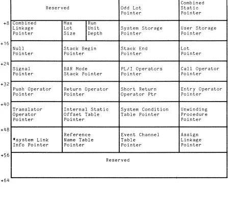
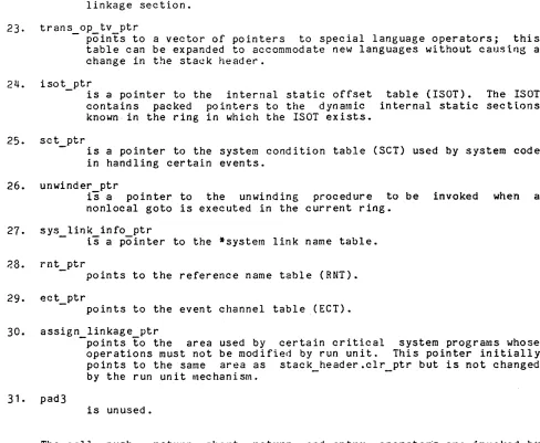
Struc ture of a Bound Segment Stack Header Format • • • • Stack Frame Format • • • • Standard Argument List
xii
Page 1-32 2-2 2-6 2-14
SECTION 1
MULTICS STANDARD OBJECT SEGMENT
A Multics object segment contains object code generated by a translator and linkage information that is used by the dynamic linking mechanism to resolve intersegment references. (See "Dynamic Linking" in the MPM Reference Guide.) The most common examples of object segments are procedure segments and data segments.
Format requirements for an object segment are primarily associated with external interfaces; thus, translator designers are permitted a great amount of freedom in the area of code and data generation. The format contains certain redundancies and unusual data structures; these are a byproduct of maintaining upward compatibility with earlier object segment formats. The dynamic linking mechanism and the standard object segment manipulation tools assume that all object segments are standard object segments.
FORMAT OF AN OBJECT SEGMENT
An object segment is divided into six sections that usually appear in the following order:
text
definition linkage
static (if present) symbol
break map (if present)
The type of information contained in each of the six sections is summarized below:
1. text
contains only pure parts of the object read-only data). It can also contain definition, linkage and symbol sections. 2. definition
segment relative
(instructions and pointers to the
contains only nonexecutable, read-only symbolic information used for dynamic linking and symbolic debugging. Since it is assumed that the definition section is infrequently referenced (as opposed to the constantly referenced text section), it should not be used as a repository for read-only constants referenced during the execution of the text section. The definition section can sometimes (as in the case of an object segment generated by the binder) be structured into definition blocks that are threaded together.
3.
linkagea. links modified at run time by the Multics linker to contain the machine address of external references, and possibly
b. data items to be allocated on a per-process basis such as the internal static storage of PL/I procedures.
4.
staticcontains the data items to be allocated on a per-process basis. The static storage may be included in the linkage section in which case there is no explicit separate static section.
5.
break mapcontains information used by the debuggers to locate breakpoints in the object segment. This section is generated by the debuggers rather than the translator and only when the segment currently contains breakpoints. Its internal format is of interest only to the debuggers.
6. symbol
contains all generated items of information that do not belong in the first five sections such as the language processor's symbol tree and historical and relocation information. The symbol section may be further structured into variable length symbol blocks threaded to form a list. The symbol section contains only pure information.
The text, definition, and symbol sections are shared by all processes that reference an object segment. Usually, a copy of the linkage section is made when an object segment is first referenced in a process. That is, the linkage section is a per~process data base. The original linkage section serves only as a copying template. An exception is made for some system programs whose link addresses are filled in at system initialization time. Their linkage sections are shared by everyone who wants to use the supplied addresses. When these programs have data items in internal storage, they have a separate static section template that is copied once per process. See the MPM Reference Guide and "Standard Stack and Linkage Area Formats" in Section 2 of this document. Normally, a segment containing break map information is in the state of being debugged and is not used by more than one process.
The object segment also contains an object map that contains the offsets and lengths of each of the sections. The object map can be located immediately before or immediately after any of the six sections. Translators normally place it immediately after the symbol section. The last word of every object segment must contain a left-justified 18-bit relative pointer to the object map.
STRUCTURE OF THE TEXT SECTION
The text section is basically unstructured, containing the -machine-language representation of a symbolic algorithm and/or pure data. Its length is usually an even number of words.
Two formats:
12/79
of the items that can appear within the text section have standard the entry sequence and the gate segment entry point transfer vector.
Entry Sequence
A standard entry sequence is usually provided for every externally accessible procedure entry point in an object segment. A standard entry sequence has the following format, defined by the system include file entry_sequence_info.incl.pI1:
dcl 1 parm desc ptrs 2 n args
-2 descriptor_relp
dcl 1 entry sequence
2 descr relp offset
2 reserved
-2 def relp
2 flags
3 basic indicator 3 revision 1 3 has descriptors 3 variable
3 function 3 pad
2 code_sequence
aligned,
fixed bin(18) unaligned unsigned,
(num descs refer(parm desc ptrs.n args)) biteT8) unaligned, - -
-aligned,
bit(18) unaligned, bit(18) unaligned, bit(18) unaligned, unaligned,
bit(1) unaligned, bit(1) unaligned, bit(1) unaligned, bit(1) unaligned, bit(1) unaligned, bit(13) unaligned, bit(36) aligned;
where:
is the number of arguments This item is optional and is equals "1"b.
expected by this external entry point. valid only if the flag has_descriptors
2. descriptor_relp
is an array of pointers (relative to the base of the text section) to the descriptors of the corresponding entry point parameters. This item is optional and is valid only if the flag has descriptors
3·
4.
equals "1"b. See "Parameter Descriptors" in Section 2. I
descr relp offset
- is- the offset (relative to the base of the text section) of the n args item. This item is optional and is valid only if the flag has_descriptors equals "1"b.
reserved
is reserved for future use and must be "O"b. 5. def_relp
is an offset (relative to the base of the definition section) to the definition of this entry point. Thus, given a pointer to an entry point, it is possible to reconstruct its symbolic name for purposes such as diagnostics or debugging.
6. flags
contains 18 binary indicators that provide information about this entry point.
basic indicator
"1"b this is the entry point of a BASIC program "O"b this is not the entry point of a BASIC program revision 1
"1"b all of the entry's parameter descriptor the entry sequence, i.e., none is in the "O"b parameter descriptor information, if
definition
information is with definition
I
has descriptors
"1"~ the entry has descriptor relp information
parameter descriptors; i.e., items n args, and descr_relp_offset contain -valid "O"b the entry does not have parameter descriptors
variable
"1"b the entry expects arguments whose number and types are variable
"O"b the number and type of arguments, if any, are not variable function
"1"b the last parameter is to be returned by this entry "O"b the last parameter is not to be returned by this entry pad
the last parameter is not to be returned by this entry
7.
code sequence- is any sequence of machine instructions satisfying Multics standard calling conventions. See "Subroutine Calling Sequences" in Section 2.
The value (i.e., offset within the text section) of the entry point corresponds to the address of the code sequence item. (The value is stored in the formal definition of the entry point. See "Structure of the Definition" below.) Thus, if entry offset is the value of the entry point ent1, then the def relp item pOinting- to the definition for ent1 is located at word
(entry_offset minus 1).
Gate Segment Entry Point Transfer Vector
For protection purposes, control must not be passed to a gate procedure at other than its defined entry points. To enforce this restriction, the first n words of a gate segment with n entry points must be an entry point transfer vector. That is, the kth word
To
<
k<
n-1) must be a transfer instruction to the kth entry point (i.e., a transfer-to the code sequence item of a standard entry sequence as described above). In this case: the value of the kth entry point is the offset of the kth transfer instruction (i.e., word k of the segment) rather than the offset of the code_sequence item of the kth entry pOint.To ensure that only these entries can be used, the hardware enforced entry bound of the gate segment must be set so that the segment can be entered only at the first n locations.
STRUCTURE OF THE DEFINITION SECTION
The definition section of an object segment contains pure information that is used by the dynamic linking mechanism.
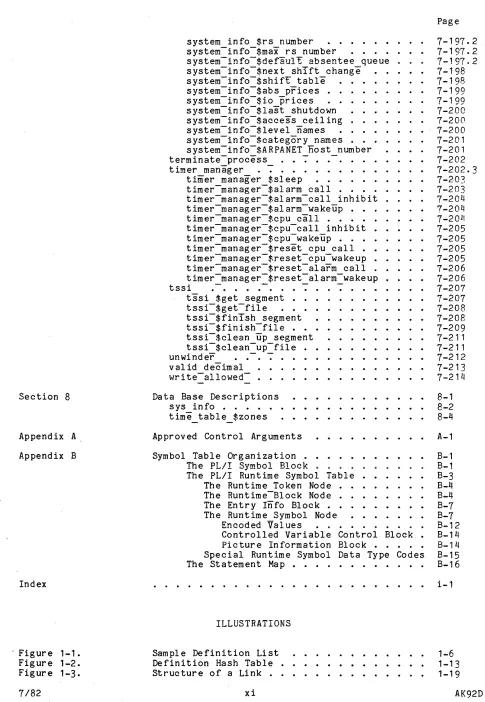
The definition section consists of a header pointing to a linked list of items describing the externally accessible named items of the object segment, followed by an unstructured area containing information describing the externally accessible named items of other object segments referenced by this object segment. The linked list is known as the definition list. The items on the list are known as definitions. The unstructured area contains expression words, type pairs, trap words, trap procedure information, and the symbolic names associated with external references.
This page intentionally left blank.
Optionally, the definition section can contain a definition hash table. If present, .' the hash table is used by the linker to expedite the search for a definition.
The information in the unstructured area of the definition section is used at runtime in conjunction with information in the linkage section to resolve the external references made by the object segment. This information is conceptually part of the linkage section, but is stored in the definition section so it can be shared among all the users of the segment.
Figure 1-1 shows the structure of the definition section. For more information concerning the interpretation of the information in the definition section see "Dynamic Linking" in Section 4 in MPM Reference Guide.
Character strings in the definition section are stored in ALM "acc" format. This format is described by the following PL/I declaration, defined by the system include file acc.intl.pI1:
dcl 1 acc
2 num chars 2 strTng
based aligned,
fixed bin(9) unsigned unaligned,
charCO refer(acc.num_chars» unaligned;
The first nine bits of the string contain the length of the string. Unused bits of the last word of the string must be zero. Such a structure is referred to as an acc string.
Definition Section Header
The definition section header resides at the base of the definition section and contains an offset (relative to the base of the definition section) to the beginning of the definition list.
dcl 1 def header ali~ned,
where:
2 def list_relp 2 unused
2 hash table relp
2 flags -3 new format 3 ignore 3 unused
bit(18) unaligned, bit(18) unaligned, bit(18) unaligned, unaligned,
bit(1) unaligned initial ("1"b), bit(1) unaligned initial (1I1I1b),
bit(16) unaligned;
1 . def list relp
- is a-relative pointer to the first definition in the definition list.
2. unused
is reserved for future use and must be "O"b.
3. hash table relp
- is
a
relative pointer to the beginning of the definition hash table.4.
flagsIf no definition hash table is present, this pointer must be "O"b.
contains 18 binary indicators that provide information about this definition section:
new format
"1"b definition section has new format "O"b definition section has old format
ignore
"1"b if new format equals "1"b, the Multics linker ignores this definition.
"O"b is an old format definition
unused
is reserved for future use and must be nO"b
I
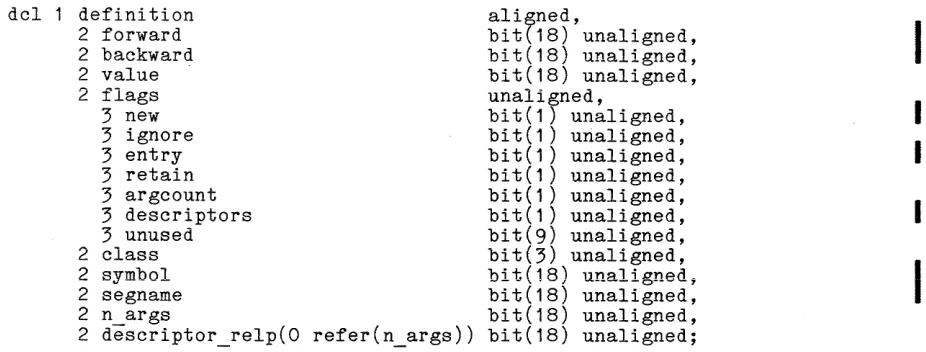
A definition that is not class-3 has the following format, defined by the
I
system include file definition.incl.pI1:dcl 1 definition 2 forward
2 backward
2 value
2 flags 3 new 3 ignore 3 entry 3 retain 3 argcount 3 descriptors 3 unused 2 class 2 symbol 2 segname 2 n args
2 descriptor_relp(O refer(n_args))
ali~ned,
bit(18) unaligned, bit(18) unaligned, bit(18) unaligned, unaligned,
bit(1) unaligned, bit(1) unaligned, bit(1) unaligned, bit(1) unaligned, bit(1) unaligned, bit(1) unaligned, bit(9) unaligned, bit(3) unaligned, bit(18) unaligned, bit(18) unaligned, bit(18) unaligned, bit(18) unaligned;
I
I
I
I
[image:21.612.96.559.556.732.2]where:
I
1. forwardis a thread (relative to the base of the definition section) to the next definition. The thread terminates when it points to a word that is O. This thread provides a single sequential list of all the definitions within the definition section.
I
2. backward3.
value4.
flagsI
I
I
5. class
I
6 . symbol12/79
is a thread (relative to the base of the definition section) to the preceding definition.
is the offset, within the section designated by the class variable (described below), of this symbolic definition.
contains 15 binary indicators that provide additional information about this definition:
new
"1 "b
"O"b
definition section has new format definition section has old format
ignore
"1 "b definition does not represent an external symbol therefore, ignored by the Multics linker
and is,
"O"b definition represents an external symbol
entry
"1 "b definition of an entry point (a variable reference through a transfer of control instruction)
"O"b definition of an external symbol that does not represent a standard entry point
retain
"1"b definition binder) "O"b definition
binder)
argcount
"1"b (obsolete) descriptors ::'n.::ar!:iatior:)
must be retained in the
can be deleted from the
definition (i. e. ,
includes a item n_args
object
object
count below
segment (by the
segment (by the
of the argument contains valid
"O"b no argument descriptor information is associated with the definition
descriptors
!l1"b ( obsolete) definition descriptor (i.e., items contain valid information) "O"b no valid descriptors exist
unused
includes an n_args and
array of argument descriptor relp below
in the definition
is reserved for future use and must be "O"b
this field contains a code indicating the section of the object segment to which value is relative. Codes are:
a
text section 1 linkage section 2 symbol section3 this symbol is a segment name
4 static section
IS an offset (relative to the base of the definition section) to an aligned acc string representing the definition's symbolic name.
7.
segname8. n_args
is an offset (relative to the base of the definition section) to the first class-3 definition of this definition block.
(obsolete) is entry point. has descriptors include file.
the number of arguments expected by this external This item is present only if argcount or equals "1"b. This item is not defined in the system
9.
descriptor relp(obsolete) is an array of pointers (relative to the base of the text section) that point to the descriptors of the corresponding entry point arguments. This item is present only if has descriptors equals "1 I1b. This item is not defined in the system include file.
The obsolete items are described here to illustrate translators should put these items in the entry sequence of See "Entry Sequence" above.
earlier versions; the text section.
In the case of a class-3 definition, the above structure is interpreted as follows:
dcl segname 2 forward 2 backward
2 segname thread 2 flags
-2 class 2 symbol 2 first relp
aligned,
bit(18) unaligned, bit(18) unaligned, bit(18) unaligned, bit(15) unaligned, bit(3) unaligned, bit(18) unaligned, bit(18) unaligned;
vrhere:
1 • forward
is the same as above.
2. backward
is the same as above.
3. segname thread
4.
flags5. class
6. symbol
7.
firstIs a thread (relative to the base of the definition section) to the next class-3 definition. The thread terminates when it points to a word that contains all O's. This thread provides a single sequential list of all class-3 definitions in the object segment.
is the same as above.
is the same as above (and has a value of 3).
is the same as above.
relp
is an offset (relative to the base of the definition section) to the first nonclass-3 definition of the definition block. If the block contains no nonclass-3 definitions, it points to the first class-3 definition of the next block. If there is no next block, it points to a word that is all O's.
The end of a definition block is determined by one of the following conditions (whichever comes first):
I
I
I
I
I
I
• forward points to an all zero word;
• the current entry's class is not 3, and forward points to a class-3 definition;
• the current definition is class 3, and both forward and first relp point to the same class-3 definition.
The threading of definition entries is shown in Figure 1-1 above. The following paragraphs describe items in the unstructured portion of the definition section.
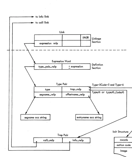
Expression Word
The expression word is the item pointed to by the expression pointer of an unsnapped link (see "Structure of the Linkage Section" below) and has the following format, defined in the system include file linkdcl.incl.pI1:
dcl 1 exp word aligned,
where:
1 • type
2. exp
Type Pair
2 type ptr 2 exp
-ptr
is an offset
bit(18) unaligned,
fixed bin(17) unaligned;
(relative to the base of the definition section) to the link's type pair.
is a signed value to be added to the offset (i. e. , offset wi thin a segment) of the resolved link.
The type pair defines the external symbol pointed to by a link and has the following format, defined in the system include file linkdcl.incl.p11:
dcl 1 type_pair
2 type aligned, bit(18) unaligned, bit(18) unaligned, bit(18) unaligned, bit(18) unaligned;
where: 1 . type
2
12/79
2 trap ptr 2 seg ptr 2 ext-ptr
assumes a value from 1 to 6:
is a self-referencing link (i.e., the segment in which the external symbol is located is the object segment containing this link or a dynamic related section of the link) of the form:
myself:O+expression,modifier
unused; it was earlier used to define a now obsolete lTP-type link.
3
4
5
6
is a link referencing a specified reference name but no symbolic offset name, of the form:
refnameIO+expression,modifier
is a link referencing both a symbolic reference name and a symbolic offset name, of the form:
refnameloffsetname+expression,modifier
is a sel f -referencing link hav ing a symbol ic offset name, of the form:
myselfloffsetname+expression,modifier
(obsolete) same as type 4 except that the external item is created if it is not found.
2. trap_ptr
is an offset (relative to the base of the definition section) to either an initialization structure (if type equals 5 and seg_ptr
I
equals 5, or if type equals 6) or to a trap word.3. seg ptr
- is a code or a pointer depending on the value of type. For types 1 and 5, this item is a code that can assume one of the following values, designating the sections of the self-referencing object segment:
o
2
4
5
is a self-reference to the object's text section; such a reference is represented symbolically as "*text".
is a self-reference to the object's linkage section; such a reference is repr esented symbol icall y as "* 1 ink" •
is a self-reference to the object's symbol section; such a reference is represented symbolically as "*symbol".
is a self-reference to the object's static section; such a reference is represented symbolically as "*static".
is a reference to an external variable managed by the linker; such a reference is represented symbolically as "*system".
For types
3,
4, and 6, this item is an offset (relative to the base of the definition section) to an aligned acc string containing the reference name portion of an external reference. (See the MPM ReferenceGuide.)
4. ext ptr
- has a meaning depending on the val ue of type. For types 1 and 3, this value is ignored and must be zero. For types 4, 5, and 6, this item is an offset (relative to the base of the definition section)
The trap word is a structure that specifies a trap procedure to be called before the link associated with the trap word is resolved by the dynamic linking mechanism. It consists of relative pointers to two links. (Links are defined under "Structure of the Linkage Section" below.) The first link defines the entry point in the trap procedure to be called. The second link defines a block No of information that is passed as one of the arguments of the trap procedure. The trap word has the following format, defined in the system include file linkdc1.incl.p11:
dcl 1 trap word 2 caTl ptr 2 arg_ptr
a1 igned ,
bit(18) unaligned, bit(18) unaligned;
where:
1. call_ptr
is an offset (relative to the base of the linkage section) to a link defining the entry point of the trap procedure.
2. arg ptr
- is an offset (relative to the base of the linkage section) to a link defining information of interest to the trap procedure.
Initialization Structure for Type ~ system and Type ~ Links
This structure specifies how a link target first referenced because of a type 5 *system or a type 6 link should be initialized. It has the following format:
dcl 1 initialization info aligned,
2 n wo r d s fix ed bin,
2 code fixed bin,
2 info (n words) bit(36) aligned;
where:
1. n words
2. code
o
3
4
3. info
7/82
is the number of words required by the new variable.
indicates what type of initialization is to be performed. It can have one of the following values:
no initialization is to be performed
copy the info array into the newly defined variable
initialize the variable as an area
is the image to be copied into the new variable. It exists only if code is 3.
n entries
-
defp 0-
defp 00 0
defp 0
0 0
-
defp 0r - - defp 0
defp 0
n entries defp block_hdrp
0 0
defp block_hdrp defp block_hdrp
1
~ n dup names
defp block hdrp
""'- ~ofn b!ock h~rn
U\"oIP .. u . ....,
~ defp block hdrp
n dup names defp block hdrp
--
defp block hdrpFigure 1-2. Definition Hash Table
,.
,
'"
,
J
~J
,. ,. ,.
I
-""
...
definition name
hash table
component name
hash table
duplicate name table
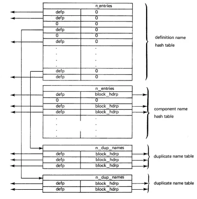
[image:27.612.149.533.125.513.2]Definition Hash Table
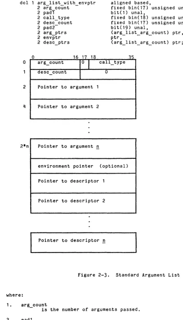
A definition hash table may be present in the definition section of an object segment. In its basic form, the definition hash table contains an array of pointers to definitions. The definition hashing algorithm selects a particular pointer. If the selected pointer does not point to the desired definition, a linear search is then performed until the appropriate definition is found or a zero pointer is encountered. The initial hash code is generated by taking the remainder of the first word of the definition name (the count and first three characters of the "acc" format string) divided by the size of the hash table. The hash table size is such that it is never more than 80% full.
In bound segments, different components may contain definitions with identical names. In this case, a second hash table is required in order to resolve ambiguities. In addition to this second hash table, a duplicate name table must be provided for each duplicated definition name.
The format of the tables described above is shown in Figure 1-2 and is described below:
The definition name hash table is pointed to by definition section header. It must contain one
a relative pointer in the nonzero entry for each non-class-3 definition name.
dcl 1 defht
where:
2 n entries 2 table
(3 defp 3 unused
1. n entries
aligned, fixed bin,
(n refer (defht.n entries»,
bit(18),
-bit(18» unal;
is the number of elements in the hash table. 2. defp
is an array of pointers to non-class-3 definitions. In the case of a duplicated definition name, a particular defp does not point directly to a definition, but rather to a duplicate name table (see below).
A component name hash table is present only if duplicated definition names are present in a bound segment. It must immediately follow the definition hash table. There is one entry in this hash table for each bound segment component name and synonym (i.e., for each class-3 definition).
dcl 1 compht
where:
2 n entries 2 table
(3 defp
3 block hdrp
1. n entries
aligned, fixed bin,
(nrefer (compht.n entries»,
bit(18),
-bit(18» unaligned;
is the number of elements in the component name hash table. 2. table
contains one nonzero element for each class-3 definition.
3. defp
is a relative pointer to a class-3 definition • . 4. block_hdrp
is a relative pointer to the first class-3 definition of the definition block containing the definition pointed to by defp.
A duplicate name table must be supplied for each duplicated definition name. Each table has one entry for each instance of the duplicated name. The definition· searching algorithm can determine whether the relative pointer retrieved from the definition hash table points to a definition or to a duplicate name table by examining the left half of the first word pointed to. A definition never contains a zero forward thread, while a duplicate name table is never nonzero in the left half of the first word.
dcl 1 dupt
where:
2 n dup names
2 table-(3 defp
3 block_hdrp
1. n dup names
al igned , fixed bin,
(n refer (dupt.n dup names»,
bit(18),
-bit(18» unaligned;
- - is the number of instances of a given duplicated name.
2. table
contains one element for each instance of the duplicated name. 3. defp
is a pointer to a non-class-3 definition.
4 • bloc k hd r p
- is a pointer to the first class-3 definition of the definition block containing the non-class-3 definition.
Definition searching with a definition hash table is done by first searching for the definition name. If no duplicate name table is encountered, no ambiguity exists and the correct definition is quickly found. If a duplicate name table is . encountered, th~ component name hash table must be searched. Then, a linear search is done on the duplicate name table to match a block_hdrp with the block_hdrp in the component name hash table.
STRUCTURE OF THE STATIC SECTION
The static section is unstructured.
STRUCTURE OF THE LINKAGE SECTION
The linkage section is subdivided into four distinct components:
1. A fixed-length header that always resides at the base of the linkage section
2. A variable length area used for internal (static) storage (optional) 3. A variable length structure of links (optional)
These four components are located wi thin the 1 i1"lkage section in the following sequence:
header
internal storage (if present) links (if present)
trap (if present)
The length of the linkage section must be an even number of words and must start on an even-word boundary; in addition, the link substructure must also begin at an even location (offset) within the linkage section.
When an object segment is first referenced in a process, its linkage section is copied into a per-process data base. At this time certain items in the copy of the header are initialized. Items not explicitly described as being initialized by the linker are set by the program that generates the object segment. In addition, the first two words of the header are filled in by the linker (when the header is copied) wi th a pointer to the beginning of the object segment's definition section. For more information see the MPM Reference Guide and "Standard Stack and Linkage Area Formats" in Section 2 of this manual.
Linkage Section Header
The header of the linkage section (in an object segment) has the following
I
format, defined in the system include file object_1ink_dcls.inc1.p11: dc1 1 virgin linkage header
2 pad - - bit(30) una1, a1 igned based,
where:
1. pad
2 defs in link 2 def offset 2 first ref re1p 2 filled in-later 2 link begin
2 linkage section 1ng 2 segno pad -2 static_length
bit(6) una1, fix ed bin ( 1 8) fix ed bin ( 1 8)
bit(144), fixed bin(18) fixed bin( 18) fix ed bin ( 18) fix ed bin ( 1 8)
is reserved for future use and must be O.
uns una1, uns una1, uns una1, uns unal, uns una1, uns una1 ;
2. defs in link
Tndicates whether or not there are definitions in the linkage section. If there are definitions in the linkage section, the value contained here is "010000"b.
3. def offset
is an offset (relative to the base of the object segment) to the base of the definition section.
I
4. first ref relpis- an offset (relative to the base of the linkage section) to the first-reference trap. This trap is activated by the linker when the first reference to this object segment is made within a given process. If the value of this item is 0, there is no first-reference trap.
I
5.
6.
7.
filled in later
-is-initialized by ihe linker when the header is copied. As a result of initialization by the linker, the first word becomes a pointer to the object segment's symbol section. It is used by the linker to snap links relative to the symbol section. The second word becomes a pointer to the original linkage section within the object segment. It is used by the link unsnapping mechanism. The last two words remain unused.
link begin
- is an offset (relative to the base of the linkage section) to the first link (the base of the link array).
linkage section lng
Is the entire length in words of the entire linkage section. 8. segno pad
- is the segment number of the object segment. It is initialized by the linker when the header is copied.
9. static length
-is the length in words of the static section and is valid even when static is part of the linkage section. It is initialized by the linker if not filled in by the translator.
Internal Storage Area
The internal storage area is an array of words used by translators to allocate internal static variables and has no predetermined structure.
Links
A linkage section may contain an array or ~lnK pairs each of which aeIlnes an external name, referenced by this object segment, whose effective address is unknown at compile time. References to external entities are made by indirect references through a link, which has been copied from the pure linkage section of an object segment to the combined linkage section in the process directory. A link initially contains a fault tag 2 modification instead of an ITS modification. When the indirect reference is attempted, the fault occurs and is intercepted by the dynamic linking mechanism. Additional information in the link is used to locate the item referenced and, if successful, the I ink is repl aced by an ITS pointer to the item. Figure 1-2 illustrates the structure of a link.
A I ink must. reside on an even location in memory, and must therefore be located at an even offset from the base of the linkage section. A link has the
fOllO:::glf;:~;;ie;:;;::d
in
t;;!;;:;:;~~;~::::l~ile
object_link_dcls.incl.pll:
II2 ringno- fixed bin(3) uns unal,
2 mbz bit(3) unal,
2 run depth fixed bin(5) unal,
2 tag- bit(6) unal,
2 expression relp fixed bin(18) uns unal, 2 mbz2 - bit(12) unal,
where:
I
1. header relp-is an offset (relative to the link itself) to the head of the linkage section. It is, in other word s, the neg at i ve val ue of the 1 ink pair's offset within the linkage section.
2. ringno
is the ring number of the ITS pointer. 3. mbz
4.
is reserved for future use and must be "Q"b. run depth
- must be Q in a generated (unsnapped) link. When the link is snapped, this field is filled in with the number of the current run unit level.
I
5. tagis a constant (46)8 that represents the hardware faul t tag 2 and distinctly identifies an unsnapped link. The snapped link (ITS pair) has a distinct (43)8 tag. See the MPM Reference Guide.
I
6. expression relpis an offset (relative to the base of the definition section) to the expression word for this link.
I
7.
8.
mbz2
is reserved for future use and must be "Q"b. modifier
is a hardware address modifier. When the 1 ink is snapped, this becomes the modifier of the ITS pair.
First-Reference Trap
It is sometimes necessary to perform certain types of initialization of an object segment when it is fir"st referenced for execution (i.e., linked to) in a given process--for example, to store some per-process information in the segment before it is used. The first-reference trap mechanism provides this facility ~ for use by various mechanisms: the status code assignment mechanism being an
example.
A first-reference trap consists of two relative pointers. The first points to a link defining the first reference procedure entry point to be invoked. The second points to a link defining a block of information to be passed as an argument to the first-reference procedure. For more details on first-reference
I
traps, see the MPM Reference Guide. The first reference trap has the following format, defined in the system include file object_link_dcls.incl.p11:I
I
7/82
dcl 1 fr traps 2 cecl vers 2 n traps 2 trap array
3 caTl relp 3 info=relp
al igned based, fixed bin, fixed bin,
(n fr traps refer(fr traps.n traps)) aligned, fixed-bin(18) uns unal,
fixed bin(18) uns unal,
where:
1 . decl vers
is the version number of the structure. 2. n traps
- specifies the number of traps.
3.
trap_arrayis an array of information about each first-reference procedure.
4. call_relp
is an offset (relative to the base of the linkage section) to a link defining a procedure to be invoked by the linker upon first reference to this object within a given process.
5. info relp
- is an offset (relative to the base of the linkage specifying a block of information to be passed as first reference procedure; if info relp is 0,
block.
This page intentionally left blank.
r---I~ to info link
to call link
Link
(46)8 Linkage
~---+---t----1 Section
r----.
expression re IpExpression Word
:. expression
~---~---~
Defintion Section
Type Pair T ype=5Code=5 and T ype=6
type trap.Je Ip
i - - - + - - - t
Type,t6 or type;5.Code;5segname_relp offsetname_relp
Init Structure Trap Pair
calLrelp nwords
action code
image
[image:35.612.59.520.57.603.2]STRUCTURE OF THE SYMBOL SECTION
I
The symbol section consists of one or more symbol headers threaded together to form a single list. A symbol header has two main functions: to document the circumstances under which the object segment was created, and to serve as a repository for information (relocation information, compiler's symbol tree, etc.) that "does not belong in any of the other sections.The symbol section must contain at least one symbol header, describing the circumstances under which the object segment was created. A symbol section can contain more than one symbol header. An example of multiple symbol headers is the case of a bound segment where in addition to the symbol header describing the segment's creation by the binder, there is also a symbol header for each of the component object segments.
Each symbol header can point to a free-format area. The free-format area can contain any information whatsoever, and the object segment will execute properly. However, the Multics debugging utilities (e.g., probe) place stringent requirements on the format of the free area, and these are followed by the translators for PL/I, FORTRAN, and COBOL. See Appendix B for additional information on the contents of the free-format area used by those three lan~uages.
Symbol Block Header
All symbol blocks have a standard fixed-format block, although not all items in the block have meaning for all symbol blocks. The description of a particular symbol block lists items that have meaning for that symbol block. The block has the following format, defined by the system include file std symbol_block.incl.pll:
7/81
del 1 std symbol block 2 dec! version
2 identifier
2 gen number
2 gen-created
? object. creat.erl 2 generator
2 gen version
3
offset 3 size2 userid
3
offset 3 size2 comment
3 offset
3
size2 text boundary
2 stat:=boundary
2 source map
2 area painter
2 backpointer
2 block size
2 next block
2 reI text
2 rel-def
2 reI-link
2 reI-symbol
2 minT truncate
2 maxi-truncate
based aligned,
fixed bin initial(l), char(8) aligned, fixed bin, fixed bin(71),
fj.,r,€'d bin(71) J
char(8), unaligned, bit(18), bit(18), unaligned, bit(18), bit(18), unaligned, bit(18), bit(18),
bit(18) unaligned, bit(18) unaligned, bit(18) unaligned, bit(18) unaligned, bit(18) unaligned, bit(18) unaligned, bit(18) unaligned, bit(18) unaligned, bit(18) unaligned, bit(18) unaligned, bit(18) unaligned, bit(18) unaligned, bit(18) unaligned;